EP0183622A2 - Verfahren und Gerät zur Wiedererkennung - Google Patents
Verfahren und Gerät zur Wiedererkennung Download PDFInfo
- Publication number
- EP0183622A2 EP0183622A2 EP85402311A EP85402311A EP0183622A2 EP 0183622 A2 EP0183622 A2 EP 0183622A2 EP 85402311 A EP85402311 A EP 85402311A EP 85402311 A EP85402311 A EP 85402311A EP 0183622 A2 EP0183622 A2 EP 0183622A2
- Authority
- EP
- European Patent Office
- Prior art keywords
- conception
- pattern
- frequency
- oscillation
- conceptions
- Prior art date
- Legal status (The legal status is an assumption and is not a legal conclusion. Google has not performed a legal analysis and makes no representation as to the accuracy of the status listed.)
- Granted
Links
Images


Classifications
-
- G—PHYSICS
- G06—COMPUTING OR CALCULATING; COUNTING
- G06F—ELECTRIC DIGITAL DATA PROCESSING
- G06F18/00—Pattern recognition
- G06F18/20—Analysing
Definitions
- the present invention relates to novel recognition method and apparatus, and more specifically to method and apparatus for recognizing patterns such as figures, letters, etc. on the basis of a novel judgment operation.
- A A (or A') where A and A' are representative of conceptions. Therefore, this judgment for identity is not the same as that can be obtained from simple comparison of physical values as in the conventional mechanical and electrical recognition apparatuses.
- the recognition of a human being can be said to be categorization of objects to be recognized. Specifically, the decision of identity is performed at various levels of categories, so that an object to be recognized can be identified in the system of known conceptions. At the same time, a property inherent to an object itself to be recognized can be known.
- the conventional mechanical and electrical recognition apparatus cannot perform the above mentioned conception identity judgment.
- a plurality of characters are extracted from a given pattern such as a letter and a figure by means of complicated procedures, and then compared with a group of characters extracted from reference patterns previously prepared, so that the distances between the given pattern and the reference patterns are calculated. Namely, only a simple measurement of one absolute amount is carried out.
- Another object of the present invention is to provide recognition method and apparatus which can judge identity of an object to be recognized, at various levels of categories.
- Still another object of the present invention is to provide pattern recognition method and apparatus which can recognize a given pattern irrespectively of the position and the angular direction of the given pattern and without requiring a complicated processing.
- the above and other objects of the present invention are accomplished by a method in accordance with one aspect of the present invention for recognizing a given object in a known system of conception which contains a group of known conceptions corresponding to different nonlinear oscillatory systems in one-to-one relation.
- This method comprises the steps of representing an given object in terms of a physical system capable of causing a nonlinear oscillation at a frequency corresponding to the conception inherent to the given object, coupling the physical system to one oscillatory system selected among the nonlinear oscillatory systems, and discriminating whether or not an entrainment occurs between the physical system and the selected oscillatory system, thereby judging the identity between the conception inherent to the given object and the known conception indicated by the selected oscillatory system.
- a method for recognizing a given object in a known system of conception which contains a group of known conceptions corresponding to different reference oscillation frequencies in one-to-one relation, comprising the steps of representing an given object in terms of a physical system capable of causing a nonlinear oscillation at a frequency corresponding to the conception inherent to the given object, selecting one known conception from the known system of conception, driving the physical system at a reference oscillation frequency corresponding to the one selected known conception, and discriminating whether or not an entrainment occurs in the physical system thereby judging the identity between the conception inherent to the given object and the one selected known conception.
- the group of known conceptions includes a plurality of independent conceptions each having one oscillation frequency which never causes entrainment with an oscillation at each of frequencies corresponding to the other independent conceptions, a plurality of general conceptions each involving at least one independent conception and each having a oscillation frequency which can cause entrainment with the oscillations at respective frequencies corresponding to all the independent conceptions involved in that general conception, and a plurality of specific conceptions each involved in one of the independent conceptions and each having a oscillation frequency which can cause entrainment with the oscillation at the frequency corresponding to the independent conception involving that specific conception.
- the physical system is first driven at frequencies corresponding to the general conceptions so as to select one general conception which has caused the entrainment. Then, the physical system is driven at frequencies corresponding to independent conceptions involved in the selected general conception so as to select one independent conception which has caused the entrainment. Further, the physical system is driven at frequencies corresponding to specific conceptions involved in the selected independent conception, thereby determining a specific conception which has caused the entrainment.
- the decision of identity is made based on whether or not the entrainment occurs. This entrainment will occur or not occur irrespectively of the position and the angular direction. Therefore, if a given object such as a pattern, analog value, color, etc. is represented by one physical system capable of causing an oscillation at a frequency corresponding to the feature of the given object, the identity of feature can be determined on the basis of whether or not the entrainment occurs between the physical system and the reference nonlinear oscillator or the oscillation of the reference frequency, without influence of the position and direction of the given object.
- a method for recognizing a given object in a known system of conception which contains a group of known conceptions corresponding to different reference oscillation frequencies in one-to-one relation, comprising the steps of representing an given object in terms of a physical system capable of causing a nonlinear oscillation at a frequency corresponding to the conception inherent to the given object, oscillating the physical system so that the oscillation of the physical system will converge at one frequency under entrainment effect, and comparing the converged frequency with the reference oscillation frequencies for identification of the given object.
- the group of known conceptions can include a plurality of independent conceptions, a plurality of general conceptions and a plurality of specific conceptions, similar to those in the method in accordance with the second aspect of the present invention.
- the comparison of the converged frequency with the reference oscillation frequencies is preferably performed by comparing the converged frequency with the oscillation frequencies of the general conceptions so as to select one general conception having a minimum oscillation frequency difference from the converged frequency, comparing the converged frequency with the oscillation frequencies of the independent conceptions involved in the selected general conception so as to select one independent conception having a minimum oscillation frequency difference from the converged frequency, and comparing the converged frequency with the oscillation frequencies of the specific conceptions involved in the selected independent conception so as to select one specific conception having a minimum oscillation frequency difference from the converged frequency, whereby the given object is categorized.
- the representation of the given object in terms of the physical system is performed by preparing a plurality of nonlinear oscillating elements located in the form of a matrix, converting the given object to a corresponding simplified pattern, and selectively mutually connecting the nonlinear oscillating elements in accordance with the simplified pattern, so that the mutually connected nonlinear oscillating elements of the matrix have as a whole an oscillation frequency inherent only to the simplified pattern.
- each of the nonlinear oscillating elements is a van der Pol oscillator.
- the given object is a two-dimensional pattern, and the two-dimensional pattern is detected by means of a two-dimensional image sensor and the obtained image is converted into a dot pattern consisting of a plurality of dots each corresponding to one nonlinear oscillating element of the matrix.
- the identity is discriminated on the basis of whether or not the oscillation frequency obtained as the result of the entrainment effect is equal or close to the reference frequencies.
- a given object such as a pattern can be cecognized regardless of its position and direction, if the given object is substituted by a nonlinear oscillating physical system.
- a method cor recognizing a given pattern comprising the steps of calculating in respect of a given pattern an index N which is represented by the ratio of the full length of the contour of a pattern and the full length of the "convex envelope" of the same pattern, comparing the calculated index N ⁇ with stored indexes N ⁇ of know patterns, and categorizing the given pattern in accordance with known patterns having indexes N falling in a predetermined difference extent ⁇ from the index N ⁇ of the given pattern.
- index N takes different values inherent to various shapes in one-to-one relation, as will be explained in detail hereinafter. Therefore, if the index N is derived in respect of a given pattern and compared with reference indexes N corresponding to the known patterns, the given pattern can be identified. In addition, if the comparison between the index N of the given pattern and the reference indexes N is performed at various significant digits, the given pattern can be recognized at different category levels.
- an apparatus for recognizing a given object in a known system of conception which contains a group of known conceptions corresponding to different - reference oscillation frequencies in one-to-one relation, comprising means for detecting a given object and forming a physical system capable of causing a nonlinear oscillation at a frequency corresponding to the conception inherent to the given object, means for oscillating the physical system so that the oscillation of the physical system will converge at one frequency under entrainment effect, and means for collating the converged frequency with the stored reference oscillation frequencies corresponding to the known conceptions.
- the physical system forming means includes a plurality of nonlinear oscillating elements located in the form of a matrix having a plurality of rows and a plurality of columns, means for producing a two-dimensional dot pattern from the given object, the dot pattern consisting of a plurality of dots each corresponding to one nonlinear oscillating elements of the matrix, means for mutually connecting the nonlinear oscillating elements of the matrix corresponding to the respective dots of the produced dot pattern so that the mutually connected nonlinear oscillating elements have as a whole one oscillation frequency inherent only to the produced dot pattern.
- an apparatus for recognizing a given pattern in a known system of pattern which contains a group of known patterns corresponding to different reference oscillation frequencies in one-to-one relation, comprising means for storing reference frequencies corresponding to the known patterns, means for detecting a given pattern so as to produce a two-dimensional simplified dot pattern representative of the given pattern, an oscillator matrix circuit including a plurality of nonlinear oscillating elements arranged in the form of a matrix having a plurality of rows and a plurality of column, means for selectively operating the oscillating elements of the matrix corresponding to the respective dots of the simplified dot pattern in such a manner that each operated oscillating element and all operated oscillating elements adjacent thereto mutually influence their oscillating condition, so that the matrix finally has one oscillating frequency corresponding to the dot pattern, and means for measuring the oscillating frequency and collating the measured oscillating frequency with the stored reference frequencies.
- the pattern detecting means includes a two-dimensional image sensor, and means receiving an image output of the image sensor for producing the dot pattern consisting of a plurality ,of dots each corresponding to one nonlinear oscillating elements of the oscillator matrix circuit.
- the means for selectively operating the oscillating elements includes means receiving the output of the dot pattern producing means for storing the dot pattern, the storing means having a plurality of memory cells located in the form of a matrix which has the same rows and columns in number as those of the oscillator matrix circuit, and switch means including a plurality of switch cells arranged in the form of a matrix which has the same rows and columns in number as those of the oscillator matrix circuit, each of the switch cells being controlled by the output of a corresponding memory cell in the storing means so as to operate a corresponding oscillating element of the oscillator matrix circuit.
- each of the nonlinear oscillating elements is a van der Pol oscillator.
- the collating means is preferably adapted to calculate the differences between the measured oscillating frequency and the stored reference frequencies so as to specify the reference frequencies having the differences from the measured oscillating frequency within a predetermined extent, whereby the given pattern is categorized.
- FIG. 1A to 1D there are shown typical simplified patterns of human, ape, quadruped and bird.
- the aforementioned index N ⁇ i.e., the ratio of twice the full length ⁇ of the contour of a pattern or shape to the full length ⁇ C of the "convex envelope" of the same pattern (2
- the values of the index N are 3.483, 3.484, 3.7 and 2.8, respectively.
- the "convex envelope” means an envelope circumscribing the given pattern and having only outwardly directed corners.
- this index N is a value inherent to each of various patterns, and this fact has been confirmed in the research of the inventors.
- the human and the ape can be said to belong to the same category, for example, "biped", since the difference ⁇ between the N ⁇ of 3,483 for the human and the N of 3,484 for the ape is less than 0.1.
- the differences ⁇ between the indexes N for the human, the quadruped and the bird are not less than 0.1, and therefore, it can be said that the human, the quadruped and the bird do not belong to the same category.
- the index N of a pattern to be recognized is compared with stored reference indexes N under a possible minimum allowable difference ⁇ , there can be known the category of an extremely narrow extent to which the pattern to be recognized belongs, i.e., the name of the pattern.
- the index N of a given pattern to be recognized is derived in accordance with the procedures mentioned above, and the obtained index N is compared with stored indexes in respect of known patterns under the condition of a suitably predetermined allowable difference ⁇ , the category to which the given pattern belongs can be known at a desired category level. In other words, a given pattern can be categorized.
- index N can be deemed to correspond to the oscillation frequency of cells which constitute a visual cortex of the human brain and which have a nonlinear oscillation characteristics.
- the index N can be regarded to correspond to the oscillation frequency of nonlinear oscillator elements such as van der Pol oscillator cells described in detail hereinafter.
- the oscillation frequency corresponding to the index N is directly obtained in the method described in detail hereinafter.
- a plurality of van der Pol oscillator cells are arranged in the form of a matrix having a plurality of rows and a plurality of columns, and each of van der Pol oscillator cells is made to be capable of coupling with van der Pol oscillator cells adjacent thereto.
- a given pattern to be recognized is converted into a "two-dimensional dot pattern.”
- the oscillator cells corresponding to the respective dots of the obtained dot pattern are selectively excited, and at the same time, each of the exciting oscillator cells are coupled with exciting oscillator cells adjacent thereto.
- the excited oscillator cells of the matrix become to oscillate as a whole at one frequency under the so called entrainment effect, which frequency depends only upon the shape of the dot pattern, and corresponds to the above mentioned index T.
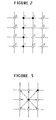
- two-dimensional dot pattern means a pattern consisting of dots positioned at respective intersections of a rectangular lattice, as shown in Figure 2. These dots are represented by one bit data: "I” indicates a black dot and "0" indicates a white dot. Therefore, the two-dimensional dot pattern is a two-dimensional bit pattern.
- the term “couple” means that the oscillator cells corresponding to the black dots (the bits of "1") in the dot pattern are coupled to oscillator cells adjacent thereto in various directions so that the coupled oscillator cells are mutually subjected to influence in respect of oscillation condition.
- a center black dot has eight peripheral dots adjacent thereto, but, since the black dot is only the upper right dot of the eight peripheral dots, the center dot is coupled with only the upper right dot.
- an unknown object (which is not limited to patterns) is converted into a nonlinear oscillating system which is typified by the above mentioned van der Pol oscillator cell matrix, and then the nonlinear oscillating system is coupled with another nonlinear oscillating system capable of oscillating at a frequency corresponding to one known conception.
- the identity between the known conception and the conception inherent to the unknown object can be determined dependently upon whether or not the entrainment occurs between the two systems.
- an unknown object such as a pattern is converted into a nonlinear oscillating system such as the van der Pol oscillator cell matrix, and then the nonlinear oscillating system is excited at a given frequency inherent to one known conception. If the oscillating system then cause the entrainment, the unknown object can be indicated by the known conception.
- a nonlinear oscillating system such as the van der Pol oscillator cell matrix
- an unknown object for example, an unknown pattern is converted into a nonlinear oscillating system (for example, a van der Pol oscillator cell matrix) and the nonlinear oscillating system is excited so that the nonlinear oscillating system causes to converge its oscillating frequency at one stable frequency for the entrainment effect. Then, the converged frequency is compared with various reference frequencies inherent to known conceptions (known patterns). As a result, if the converged frequency is consistent with one of the reference frequency, the unknown object can be said to be expressed by a known conception corresponding to the consistent reference frequency.
- a nonlinear oscillating system for example, a van der Pol oscillator cell matrix
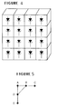
- a plurality of van der Pol oscillator cells are located in the form of a two-dimensional lattice or a matrix, as shown in Figure 4.
- oscillator cells corresponding to the black dots of a given dot pattern are selected, and then, each of the selected oscillator cells is excited at a frequency determined on the basis of the number of adjacent black dots (adjacent "1" bits).
- an interaction is given between each couple of adjacent selected oscillator cells, for example through a resistor having a resistance in proportion to the difference of velocity between each couple of adjacent selected oscillator cells.
- this oscillating frequency depends only upon the shape of the given pattern.
- the oscillating frequency represents the shape of the given pattern.
- the nonlinear oscillator cell matrix as shown in Figure 4 even if the given pattern is rotated at 90°, 180° or 270°, or inverted or parallel-shifted, the final oscillating frequency never changes.
- the necessary processing can be carried out within the time of 0.1 to 0.2 seconds, irrespectively of increase in the degree of freedom in the pattern recognition which would be given by rotation, parallel shift, etc. of a given pattern. Besides, since a pattern is finally converted into one frequency, when patterns are stored or transferred, necessary memory capacity and channel capacity can be made small.
- nonlinear oscillator cells which constitute a nonlinear oscillator cell matrix capable of causing the entrainment.
- One typical example of such nonlinear oscillator cells is a van der Pol oscillator cell, as mentioned above.
- This van der Pol oscillator cell can be defined as having an operational characteristics expressed by the following equation: where x represents a magnitude such as a voltage in an electric circuit and a force in a physical system;
- the inherent frequency w i of each oscillator cell is determined in accordance with the following equation: where w is a standard frequency, for example,
- FIG. 6A there is shown a dot pattern diagram illustrating the conception of "adjacent dots".
- a dot A is a center dot
- dots 1 to 4 are adjacent to the center dot A in a "tetra-adjacent-direction”
- dots 1 to 8 are adjacent to the center dot A in a "octa-adjacent-direction
- dots 1 to 12 in a "dodeca-adjacent-direction”.
- the "coupled-dot pattern” is defined to be a dot pattern constituted of only a plurality black dots each of which is adjacent to at least one black dot.
- dots a and b do not form a coupled-dot pattern in accordance with the "tetra-adjacent-direction", but constitute a coupled-dot pattern in the "octa-adjacent-direction.”
- dots a and c do not provide a coupled-dot pattern not only in the tetra-adjacent-direction but also in the octa-adjacent-direction.
- the resolution is higher in the octa-adjacent-direction than in the tetra-adjacent-direction, and further improved in the dodeca-adjacent-direction.
- a given pattern can be recognized in the following manner.
- a given pattern is converted into a dot pattern, which is further converted into a coupled-dot pattern.
- oscillator cells corresponding to the respective dots of the coupled-dot pattern are respectively driven at the inherent frequencies w which are determined in accordance with the equation (2), while adding the interactions between adjacent oscillator cells in accordance with the equation (3). Consequently, one frequency can be obtained from the result of the entrainment effect, and then collated with stored reference frequencies f l , f 2 , f 3 ... of known patterns. If the entrainment frequency is the same or very close to one of the reference frequencies, the given pattern is judged to be the same or similar to the known pattern represented by the coincident reference frequency.
- the resolution of the pattern recognition depends upon the number of adjacent directions along which the van der Pol oscillator cells are coupled.
- these patterns will be deemed to be the same coupled-dot pattern on the basis of the tetra-adjacent-direction.
- these patterns are modified as shown in Figures 8A, 8B and 8C.
- the coupled-dot patterns shown in Figures 8A and 8B are the same but can be distinguished from that shown in Figure 8C.
- FIG. 9 there are shown examples of coupled-dot patterns and corresponding entrainment frequency.
- the solid lines show the coupled relations between black dots which constitute a coupled-dot pattern, i.e., the interacting relations between the van der Pol oscillator cells.
- FIG. 10 there is shown a block diagram showing an overall structure of the pattern recognizing apparatus in accordance with the present invention.
- An unknown pattern is image-detected and converted into a dot pattern by a feature extractor 15.
- the feature extractor 15 includes an image sensor (not shown) which photographs the unknown pattern and generates an analog video signal, which is then fed to a threshold circuit (not shown) where the video signal is converted into binary video signals each of which indicates one dot of the dot pattern.
- the output of the feature extractor 15 is connected to a van der Pol oscillator cell matrix 16, which outputs an entrainment frequency f a to an collator 17 associated with a memory 18 storing reference frequencies f l , f 2 , f 3 ... of known patterns. Therefore, the entrainment frequency f a is compared with stored reference frequencies f l , f 2 , f 3 ... in the collator 17, so that unknown pattern is identified by a known pattern corresponding to one reference frequency which is constituent with the entrainment frequency in a desired allowable difference extent. In this connection, the unknown pattern can be recognized by a category having a desired extent from general conception to a specific name.
- the binary video signals generated in the feature extractor 15 are fed through a line 26 to a memory cell matrix 20, as shown in Figure 11.
- the memory cell matrix 20 is composed of a number of memory cells located in the form of a matrix having a plurality of rows and a plurality of columns sufficient to form a necessary size of dot pattern.
- the respective binary signals are temporarily stored in the corresponding memory cells of the matrix memory 20, respectively, so that a dot pattern is formed in the memory cell matrix.
- the outputs of the respective memory cells are connected through parallel lines 28 to corresponding switch cells of a spatial switch 22, which comprises the same number of switch cells as that of the memory cells. These switch cells are arranged to form a matrix of the same size as that of the memory matrix 20.
- the spatial switch 22 is associated with a voltage generator and frequency counter 24, and is connected to control a van der Pol oscillator cell matrix 16.
- This oscillator cell matrix 16 includes van der Pol cells 30 of the same number as that of the switch cells, and these cells 30 are located to form a matrix of the same size as the switch cell matrix of the spatial switch 22.
- each of the van der Pol cells 30 has a non-inverted input Vin i , an inverted input Vin 2 and one output Vout, which are connected to the corresponding one switch cell of the spatial switch 22.
- the switch calls of the spatial switch 22 includes five analog switch elements 36 in a column direction, as shown in Figure 12.
- the five analog switch elements 36 are turned on and off by the output Bit (i, j) of the corresponding memory cell in the memory matrix 20.
- One of the five analog switch elements 36 is connected at its end through a resistor and a capacitor to the output Vout of the corresponding van der Pol cell (i, j), and also connected at its other end through a line 32 to the voltage generator and frequency counter, 24.
- the remaining four analog switch elements 36 operate to selectively connect an voltage output line 38 of the voltage generator and frequency counter 24 to the non-inverted and inverted inputs Vin l and Vin 2 of the van der Pol cells 30.
- the voltage output line 38 includes a pair of lines 38A and 38B as shown in Figure 12, and the four analog switch elements 36 associated to each van der Pol cell (i, j) are connected as shown in Figure 12, so as to supply feedback voltages Vin l and Vin 2 through the lines 38A and 38B to the adjacent van der Pol cells (i, j-1) and (i, j+1).
- These feedback voltages Vin 1 and Vin 2 are determined as follows: Namely, the voltage Vin 1 applied to each cell is obtained by multiplying the output voltage Vout of that cell by the total number of adjacent black dots (adjacent bits of "1"). The voltage Vin 2 is determined by summing the output voltages Vout of the adjacent cells corresponding to the adjacent black dots (adjacent bits of "1").
- the van der Pol cells 30 receiving such feedback voltages can be constructed as shown in Figure 13, for example.
- the feedback voltage Vin 2 is applied through an inverter 40 to one input of an adder 42, whose other input is adapted to receive the feedback voltage Vin 2 .
- An output of the adder 42 is differentiated by a differentiating circuit 44 and then divided by a divider 46.
- the output of the divider 46 is connected to one input of another adder 48 as a voltage representing the interaction items in the equation (3).
- the feedback voltage Vin l is divided by another divider 52 and supplied to the other input of the adder 48 as a voltage defining a portion of the inherent frequency expressed by the equation (2).
- the output of the adder 43 is connected through a line 54 to an Esaki diode oscillator 50.
- the oscillator 50 can be constructed as shown in Figure 14. Namely, the oscillator 50 includes an Esaki diode 60 having an anode connected to the line 54 and grounded through a feedback resistor 70. A LC circuit 61 and a variable resistor 62 are connected across the diode 60, and a constant DC voltage source 64 is connected to the cathode of the diode 60.
- This oscillator 50 is one kind of LC oscillating circuit utilizing the negative resistance characteristics of the Esaki diode 60. Namely, the current flowing through the Esaki diode 60 is approximately expressed by a third order function of the voltage across the diode 60, so that the output voltage of the oscillator using the Esaki diode can be expressed by the equation (1).
- the variable resistor 62 is used to adjust the negative resistance characteristics of the diode 60 so as to ultimately control the magnitude of variation in the output voltage Vout.
- the change in the resistance of the variable resistor 62 corresponds to the change of the coefficients a and b in the equation (1).
- the factor x in the equation (1) can be expressed as follows:
- this oscillator 50 operates as expressed by the equation (3).
Landscapes
- Engineering & Computer Science (AREA)
- Data Mining & Analysis (AREA)
- Theoretical Computer Science (AREA)
- Computer Vision & Pattern Recognition (AREA)
- Bioinformatics & Cheminformatics (AREA)
- Bioinformatics & Computational Biology (AREA)
- Artificial Intelligence (AREA)
- Evolutionary Biology (AREA)
- Evolutionary Computation (AREA)
- Physics & Mathematics (AREA)
- General Engineering & Computer Science (AREA)
- General Physics & Mathematics (AREA)
- Life Sciences & Earth Sciences (AREA)
- Image Analysis (AREA)
- Cosmetics (AREA)
Applications Claiming Priority (4)
| Application Number | Priority Date | Filing Date | Title |
|---|---|---|---|
| JP59249249A JPH06105466B2 (ja) | 1984-11-26 | 1984-11-26 | 画像パターン認識方法 |
| JP249249/84 | 1984-11-26 | ||
| JP59249250A JPS61127076A (ja) | 1984-11-26 | 1984-11-26 | パタ−ン認識装置 |
| JP249250/84 | 1984-11-26 |
Publications (3)
| Publication Number | Publication Date |
|---|---|
| EP0183622A2 true EP0183622A2 (de) | 1986-06-04 |
| EP0183622A3 EP0183622A3 (en) | 1989-03-15 |
| EP0183622B1 EP0183622B1 (de) | 1993-05-26 |
Family
ID=26539179
Family Applications (1)
| Application Number | Title | Priority Date | Filing Date |
|---|---|---|---|
| EP85402311A Expired - Lifetime EP0183622B1 (de) | 1984-11-26 | 1985-11-26 | Verfahren und Gerät zur Wiedererkennung |
Country Status (4)
| Country | Link |
|---|---|
| US (1) | US4760603A (de) |
| EP (1) | EP0183622B1 (de) |
| CA (1) | CA1243408A (de) |
| DE (1) | DE3587363T2 (de) |
Cited By (2)
| Publication number | Priority date | Publication date | Assignee | Title |
|---|---|---|---|---|
| EP0288332A3 (en) * | 1987-02-22 | 1990-11-28 | Research Development Corporation Of Japan | Pattern recognition system |
| EP0339867A3 (de) * | 1988-04-26 | 1991-07-03 | Canon Kabushiki Kaisha | Bewegungserkennungsgerät |
Families Citing this family (1)
| Publication number | Priority date | Publication date | Assignee | Title |
|---|---|---|---|---|
| US7693212B2 (en) * | 2005-10-10 | 2010-04-06 | General Electric Company | Methods and apparatus for frequency rectification |
Family Cites Families (6)
| Publication number | Priority date | Publication date | Assignee | Title |
|---|---|---|---|---|
| US3332064A (en) * | 1960-07-26 | 1967-07-18 | Gen Electric | Double-frequency coded symbol reader |
| US3271761A (en) * | 1963-11-29 | 1966-09-06 | Ibm | Curvature and shape detection |
| US3482211A (en) * | 1965-06-07 | 1969-12-02 | Ibm | Character recognition system |
| US3509534A (en) * | 1965-09-20 | 1970-04-28 | Philco Ford Corp | Character recognition apparatus |
| US3822381A (en) * | 1971-03-08 | 1974-07-02 | Wisconsin Alumni Res Found | Multimode oscillators for pattern recognition |
| US4115803A (en) * | 1975-05-23 | 1978-09-19 | Bausch & Lomb Incorporated | Image analysis measurement apparatus and methods |
-
1985
- 1985-11-26 DE DE85402311T patent/DE3587363T2/de not_active Expired - Fee Related
- 1985-11-26 US US06/801,991 patent/US4760603A/en not_active Expired - Lifetime
- 1985-11-26 CA CA000496180A patent/CA1243408A/en not_active Expired
- 1985-11-26 EP EP85402311A patent/EP0183622B1/de not_active Expired - Lifetime
Cited By (2)
| Publication number | Priority date | Publication date | Assignee | Title |
|---|---|---|---|---|
| EP0288332A3 (en) * | 1987-02-22 | 1990-11-28 | Research Development Corporation Of Japan | Pattern recognition system |
| EP0339867A3 (de) * | 1988-04-26 | 1991-07-03 | Canon Kabushiki Kaisha | Bewegungserkennungsgerät |
Also Published As
| Publication number | Publication date |
|---|---|
| EP0183622A3 (en) | 1989-03-15 |
| US4760603A (en) | 1988-07-26 |
| DE3587363D1 (de) | 1993-07-01 |
| EP0183622B1 (de) | 1993-05-26 |
| CA1243408A (en) | 1988-10-18 |
| DE3587363T2 (de) | 1994-01-20 |
Similar Documents
| Publication | Publication Date | Title |
|---|---|---|
| Higle et al. | Statistical verification of optimality conditions for stochastic programs with recourse | |
| Koczy et al. | Size reduction by interpolation in fuzzy rule bases | |
| Froeschlé et al. | Fast Lyapunov indicators. Application to asteroidal motion | |
| EP0339867B1 (de) | Bewegungserkennungsgerät | |
| KR910006859A (ko) | 학습형 의지 결정 지원 시스템 | |
| JP2000512046A (ja) | 統計に基づくパターン識別のための方法及び装置 | |
| EP0095332B1 (de) | Positionsbestimmungsvorrichtung | |
| US6421654B1 (en) | Learning method generating small size neurons for data classification | |
| US5239140A (en) | Pattern input apparatus | |
| US4760603A (en) | Method and apparatus of recognition | |
| Murthy | Qualitative Reasoning at Multiple Resolutions. | |
| Revalski | Hadamard and strong well-posedness for convex programs | |
| Datta et al. | Fractalization route to strange nonchaotic dynamics | |
| EP1420263A2 (de) | Referenzspannungsquelle | |
| Yamasaki et al. | Analog pattern classifier with flexible matching circuitry based on principal-axis-projection vector representation | |
| EP0222021A1 (de) | Digital/analog-umwandler | |
| Nichols et al. | Practical evaluation of invariant measures for the chaotic response of a two-frequency excited mechanical oscillator | |
| Colagrande et al. | Linear attention with global context: A multipole attention mechanism for vision and physics | |
| EP0567983B1 (de) | Lernende Wellenformerkennungseinrichtung | |
| Lappalainen | Using an MDL-based cost function with neural networks | |
| Sakoda et al. | Address recognition system based on feature extraction from gray scale | |
| Liang et al. | Roughness of fuzzy sets based on two new operators | |
| US20030154225A1 (en) | Method for determining Hopf bifurcation points of a periodic state description of a technical system; computer program and computer program product executing the method; storage medium, computer memory, electric carrier signal, and data carrier storing the computer program; and method for downloading a computer program containing the method | |
| JPS61127076A (ja) | パタ−ン認識装置 | |
| JPH06105466B2 (ja) | 画像パターン認識方法 |
Legal Events
| Date | Code | Title | Description |
|---|---|---|---|
| PUAI | Public reference made under article 153(3) epc to a published international application that has entered the european phase |
Free format text: ORIGINAL CODE: 0009012 |
|
| 17P | Request for examination filed |
Effective date: 19860226 |
|
| AK | Designated contracting states |
Kind code of ref document: A2 Designated state(s): CH DE FR GB LI SE |
|
| PUAL | Search report despatched |
Free format text: ORIGINAL CODE: 0009013 |
|
| AK | Designated contracting states |
Kind code of ref document: A3 Designated state(s): CH DE FR GB LI SE |
|
| 17Q | First examination report despatched |
Effective date: 19901024 |
|
| GRAA | (expected) grant |
Free format text: ORIGINAL CODE: 0009210 |
|
| AK | Designated contracting states |
Kind code of ref document: B1 Designated state(s): CH DE FR GB LI SE |
|
| REF | Corresponds to: |
Ref document number: 3587363 Country of ref document: DE Date of ref document: 19930701 |
|
| ET | Fr: translation filed | ||
| PLBE | No opposition filed within time limit |
Free format text: ORIGINAL CODE: 0009261 |
|
| STAA | Information on the status of an ep patent application or granted ep patent |
Free format text: STATUS: NO OPPOSITION FILED WITHIN TIME LIMIT |
|
| 26N | No opposition filed | ||
| EAL | Se: european patent in force in sweden |
Ref document number: 85402311.6 |
|
| PGFP | Annual fee paid to national office [announced via postgrant information from national office to epo] |
Ref country code: CH Payment date: 20001016 Year of fee payment: 16 |
|
| PGFP | Annual fee paid to national office [announced via postgrant information from national office to epo] |
Ref country code: SE Payment date: 20001017 Year of fee payment: 16 |
|
| PGFP | Annual fee paid to national office [announced via postgrant information from national office to epo] |
Ref country code: FR Payment date: 20001019 Year of fee payment: 16 |
|
| PGFP | Annual fee paid to national office [announced via postgrant information from national office to epo] |
Ref country code: GB Payment date: 20001121 Year of fee payment: 16 |
|
| PGFP | Annual fee paid to national office [announced via postgrant information from national office to epo] |
Ref country code: DE Payment date: 20010126 Year of fee payment: 16 |
|
| PG25 | Lapsed in a contracting state [announced via postgrant information from national office to epo] |
Ref country code: GB Free format text: LAPSE BECAUSE OF NON-PAYMENT OF DUE FEES Effective date: 20011126 |
|
| PG25 | Lapsed in a contracting state [announced via postgrant information from national office to epo] |
Ref country code: SE Free format text: LAPSE BECAUSE OF NON-PAYMENT OF DUE FEES Effective date: 20011127 |
|
| PG25 | Lapsed in a contracting state [announced via postgrant information from national office to epo] |
Ref country code: LI Free format text: LAPSE BECAUSE OF NON-PAYMENT OF DUE FEES Effective date: 20011130 Ref country code: CH Free format text: LAPSE BECAUSE OF NON-PAYMENT OF DUE FEES Effective date: 20011130 |
|
| REG | Reference to a national code |
Ref country code: GB Ref legal event code: IF02 |
|
| EUG | Se: european patent has lapsed |
Ref document number: 85402311.6 |
|
| PG25 | Lapsed in a contracting state [announced via postgrant information from national office to epo] |
Ref country code: DE Free format text: LAPSE BECAUSE OF NON-PAYMENT OF DUE FEES Effective date: 20020702 |
|
| REG | Reference to a national code |
Ref country code: CH Ref legal event code: PL |
|
| GBPC | Gb: european patent ceased through non-payment of renewal fee |
Effective date: 20011126 |
|
| PG25 | Lapsed in a contracting state [announced via postgrant information from national office to epo] |
Ref country code: FR Free format text: LAPSE BECAUSE OF NON-PAYMENT OF DUE FEES Effective date: 20020730 |
|
| REG | Reference to a national code |
Ref country code: FR Ref legal event code: ST |
|
| REG | Reference to a national code |
Ref country code: FR Ref legal event code: ST |