EP0183637B1 - Vorrichtung zum genauen Bestimmen des Pulveranteiles in einem strömenden Gas - Google Patents
Vorrichtung zum genauen Bestimmen des Pulveranteiles in einem strömenden Gas Download PDFInfo
- Publication number
- EP0183637B1 EP0183637B1 EP85630205A EP85630205A EP0183637B1 EP 0183637 B1 EP0183637 B1 EP 0183637B1 EP 85630205 A EP85630205 A EP 85630205A EP 85630205 A EP85630205 A EP 85630205A EP 0183637 B1 EP0183637 B1 EP 0183637B1
- Authority
- EP
- European Patent Office
- Prior art keywords
- powder
- gas
- flow rate
- mass flow
- carrier gas
- Prior art date
- Legal status (The legal status is an assumption and is not a legal conclusion. Google has not performed a legal analysis and makes no representation as to the accuracy of the status listed.)
- Expired
Links
- 239000000843 powder Substances 0.000 title claims description 50
- 239000007789 gas Substances 0.000 claims description 31
- 230000005855 radiation Effects 0.000 claims description 28
- 239000012159 carrier gas Substances 0.000 claims description 27
- 230000005540 biological transmission Effects 0.000 claims description 8
- OKTJSMMVPCPJKN-UHFFFAOYSA-N Carbon Chemical compound [C] OKTJSMMVPCPJKN-UHFFFAOYSA-N 0.000 claims description 7
- 239000002245 particle Substances 0.000 claims description 7
- 239000011236 particulate material Substances 0.000 claims description 7
- 239000000463 material Substances 0.000 claims description 6
- 230000000149 penetrating effect Effects 0.000 claims description 5
- 229910002804 graphite Inorganic materials 0.000 claims description 4
- 239000010439 graphite Substances 0.000 claims description 4
- 241000269627 Amphiuma means Species 0.000 claims description 3
- XEEYBQQBJWHFJM-BJUDXGSMSA-N Iron-55 Chemical compound [55Fe] XEEYBQQBJWHFJM-BJUDXGSMSA-N 0.000 claims description 3
- 230000002285 radioactive effect Effects 0.000 claims 1
- 238000005259 measurement Methods 0.000 description 5
- 229910052799 carbon Inorganic materials 0.000 description 3
- 238000000034 method Methods 0.000 description 3
- 239000004033 plastic Substances 0.000 description 3
- LTPBRCUWZOMYOC-UHFFFAOYSA-N Beryllium oxide Chemical compound O=[Be] LTPBRCUWZOMYOC-UHFFFAOYSA-N 0.000 description 2
- 239000000919 ceramic Substances 0.000 description 2
- 238000010586 diagram Methods 0.000 description 2
- 239000000203 mixture Substances 0.000 description 2
- 230000003068 static effect Effects 0.000 description 2
- 238000011144 upstream manufacturing Methods 0.000 description 2
- PWHULOQIROXLJO-UHFFFAOYSA-N Manganese Chemical compound [Mn] PWHULOQIROXLJO-UHFFFAOYSA-N 0.000 description 1
- 229910000990 Ni alloy Inorganic materials 0.000 description 1
- 230000002411 adverse Effects 0.000 description 1
- 229910052790 beryllium Inorganic materials 0.000 description 1
- ATBAMAFKBVZNFJ-UHFFFAOYSA-N beryllium atom Chemical compound [Be] ATBAMAFKBVZNFJ-UHFFFAOYSA-N 0.000 description 1
- 238000009530 blood pressure measurement Methods 0.000 description 1
- 230000001276 controlling effect Effects 0.000 description 1
- 230000007547 defect Effects 0.000 description 1
- 239000007772 electrode material Substances 0.000 description 1
- 230000037406 food intake Effects 0.000 description 1
- 239000000446 fuel Substances 0.000 description 1
- 230000001788 irregular Effects 0.000 description 1
- DNNSSWSSYDEUBZ-OUBTZVSYSA-N krypton-85 Chemical compound [85Kr] DNNSSWSSYDEUBZ-OUBTZVSYSA-N 0.000 description 1
- 230000007774 longterm Effects 0.000 description 1
- 229910052748 manganese Inorganic materials 0.000 description 1
- 239000011572 manganese Substances 0.000 description 1
- 239000011159 matrix material Substances 0.000 description 1
- PXHVJJICTQNCMI-LZFNBGRKSA-N nickel-65 Chemical compound [65Ni] PXHVJJICTQNCMI-LZFNBGRKSA-N 0.000 description 1
- 239000004482 other powder Substances 0.000 description 1
- 238000007750 plasma spraying Methods 0.000 description 1
- 230000001105 regulatory effect Effects 0.000 description 1
- 239000007921 spray Substances 0.000 description 1
- 238000007751 thermal spraying Methods 0.000 description 1
- 230000001988 toxicity Effects 0.000 description 1
- 231100000419 toxicity Toxicity 0.000 description 1
- 238000005303 weighing Methods 0.000 description 1
Images
Classifications
-
- H—ELECTRICITY
- H05—ELECTRIC TECHNIQUES NOT OTHERWISE PROVIDED FOR
- H05H—PLASMA TECHNIQUE; PRODUCTION OF ACCELERATED ELECTRICALLY-CHARGED PARTICLES OR OF NEUTRONS; PRODUCTION OR ACCELERATION OF NEUTRAL MOLECULAR OR ATOMIC BEAMS
- H05H1/00—Generating plasma; Handling plasma
- H05H1/24—Generating plasma
- H05H1/26—Plasma torches
- H05H1/32—Plasma torches using an arc
- H05H1/42—Plasma torches using an arc with provisions for introducing materials into the plasma, e.g. powder or liquid
-
- G—PHYSICS
- G01—MEASURING; TESTING
- G01F—MEASURING VOLUME, VOLUME FLOW, MASS FLOW OR LIQUID LEVEL; METERING BY VOLUME
- G01F1/00—Measuring the volume flow or mass flow of fluid or fluent solid material wherein the fluid passes through a meter in a continuous flow
- G01F1/74—Devices for measuring flow of a fluid or flow of a fluent solid material in suspension in another fluid
Definitions
- the present invention concerns an apparatus for determining the mass flow rate of powder material entrained in a flowing gas stream.
- the technical field of the invention is that of accurate real time measurement of particulate material in flowing gas stream.
- the invention relates to a device for measuring the amount of powder entrained in a flowing carrier gas stream.
- the apparatus includes a mass flow sensor and a pressure sensor for characterizing the flow of the carrier gas ans a sensor using penetrating radiation for measuring the attenuation characteristics of the carrier gas after entrainment of the powder. Knowing the flow rate and pressure of the carrier gas and the radiation measured density of the combined mixture, a calculation can be made which provides a highly accurate measure of the mass flow rate of the entrained powder.
- the apparatus of the present invention includes:
- Another aspect of the invention is characterised by claim 2.
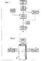
- FIG. 1 shows a block diagram of the components of the apparatus of the present invention.
- a powder feeder 1 Central to the apparatus of Figure 1 is a powder feeder 1 which is of conventional nature.
- the particular powder feed apparatus employed is one commercially available from the Plasmadyne Corporation which employs a horizontally disposed rotating disk having a plurality of apertures near its rim. The disk is rotated so that the apertures periodically cover and uncover an aperture in an underlying stationary disk.
- the amount of powder passing through the aperture in the stationary disk is related to the rotational speed of the disk which in turn is controllable by external means so that the powder flow rate can be varied at will.
- a variety of other powder dispensing apparatuses are commercially available and the particular method of dispensing the powder is not relevant to the present invention so long as the flow rate can be varied at will.
- the mass flow sensor 2 is a commercially available device supplied by the Mathison Corporation, a sensor which operates on the general principle of measuring gas mass flow by measuring heat transfer from a heater to a downstream temperature sensor. It will be noted that the carrier gas mass flow is measured prior to the powder entrainment.
- the carrier gas pressure sensor may be arranged either upstream or downstream of the powder feeder 1. It is preferred, however, to have the pressure sensor 3 upstream of the powder feeder 1 so as to avoid potential problems which result from ingestion of powder by the pressure sensor 3.
- the mixed stream passes through a radiation sensor 4 which senses the relative density of the mixed gas and particulate stream by measuring the attenuation of the transmitted beam of radiation.
- Figure 2 shows a drawing of the radiation transmission gauge which has been developed for this application.
- the flowing stream of mixed particulate and carrier gas passes through a thin wall tube 10 which is transmissive of the radiation selected.
- graphite of the type commercially available from POCO Division of Union-76 Corporation and described as high density (1.74g/cm3) extremely high strenght EDM electrode material is a suitable material for this application.
- the atomic number of carbon is sufficiently low that the x-ray beam employed passes readily through the tube with minimal attenuation.
- the tube 10 is sufficiently durable for hundreds of hours of use and is cheap and readily replaceable when needed.
- the tube 10 must be electrically conductive and must be well grounded.
- the radiation source 14 employed must be selected to be sufficiently powerful so as to penetrate the tube walls but must not be so powerful as to pass through the flowing particulate materials unimpeded.
- an iron 55 isotope source has been used with great success. Iron 55 decays to form manganese and produces thereby a characteristic x-ray radiation having a characteristic intensity of about 5.9 keV. This radiation has proved to be ideal for the measurement of flowing streams of nickel alloy, ceramic and plastic powders, but other sources such as Krypton 85 and nickel 65 might be used as well.
- An ion chamber is a suitable detecting means for the gauging system. Having determined the pressure and mass flow of the carrier gas and the radiation attenuation caused by the combined stream of particulate material and carrier gas, the mass flow rate of the particulate material can be calculated using the following equation.
- F is the mass flow of the carrier gas
- lo is the radiation intensity observed when the gas is flowing with no entrained powder
- I is the radiation intensity observed when the gas plus powder stream is flowing.
- M is an attenuation coefficient. In practice M and A are experimentally determined at at least two different gas flow rates by flowing powder through the gauge for a fixed period of time and weighing the resultant powder while measuring the relative amounts of transmitted radiation. In the event that it is found not to be necessary to incorporate the pressure, it may be equal to 1 in the equation.
Landscapes
- Physics & Mathematics (AREA)
- Engineering & Computer Science (AREA)
- Plasma & Fusion (AREA)
- Spectroscopy & Molecular Physics (AREA)
- Fluid Mechanics (AREA)
- General Physics & Mathematics (AREA)
- Measuring Volume Flow (AREA)
- Analysing Materials By The Use Of Radiation (AREA)
Claims (5)


Applications Claiming Priority (2)
| Application Number | Priority Date | Filing Date | Title |
|---|---|---|---|
| US675801 | 1984-11-28 | ||
| US06/675,801 US4603257A (en) | 1984-11-28 | 1984-11-28 | Method and apparatus for accurate determination of powder content in flowing gas stream |
Publications (2)
| Publication Number | Publication Date |
|---|---|
| EP0183637A1 EP0183637A1 (de) | 1986-06-04 |
| EP0183637B1 true EP0183637B1 (de) | 1989-04-12 |
Family
ID=24712033
Family Applications (1)
| Application Number | Title | Priority Date | Filing Date |
|---|---|---|---|
| EP85630205A Expired EP0183637B1 (de) | 1984-11-28 | 1985-11-27 | Vorrichtung zum genauen Bestimmen des Pulveranteiles in einem strömenden Gas |
Country Status (4)
| Country | Link |
|---|---|
| US (1) | US4603257A (de) |
| EP (1) | EP0183637B1 (de) |
| JP (1) | JPS61142418A (de) |
| DE (1) | DE3569412D1 (de) |
Families Citing this family (21)
| Publication number | Priority date | Publication date | Assignee | Title |
|---|---|---|---|---|
| DE3721875A1 (de) * | 1987-07-02 | 1989-01-12 | Gema Ransburg Ag | Verfahren und einrichtung fuer eine pulverspruehbeschichtungsanlage |
| US4835390A (en) * | 1987-10-19 | 1989-05-30 | Electric Power Research Institute, Inc. | Apparatus and method for measuring bulk density using positron scattering and annihilation |
| GB2212903B (en) * | 1987-11-24 | 1991-11-06 | Rolls Royce Plc | Measuring two phase flow in pipes. |
| US5837960A (en) * | 1995-08-14 | 1998-11-17 | The Regents Of The University Of California | Laser production of articles from powders |
| US6046426A (en) * | 1996-07-08 | 2000-04-04 | Sandia Corporation | Method and system for producing complex-shape objects |
| DE19650112C1 (de) * | 1996-12-03 | 1998-05-20 | Wagner Int | Einrichtung und Verfahren zum Messen eines Pulver-Massestromes |
| US6429402B1 (en) | 1997-01-24 | 2002-08-06 | The Regents Of The University Of California | Controlled laser production of elongated articles from particulates |
| US6165542A (en) * | 1998-12-23 | 2000-12-26 | United Technologies Corporation | Method for fabricating and inspecting coatings |
| US7001672B2 (en) | 2003-12-03 | 2006-02-21 | Medicine Lodge, Inc. | Laser based metal deposition of implant structures |
| US7666522B2 (en) * | 2003-12-03 | 2010-02-23 | IMDS, Inc. | Laser based metal deposition (LBMD) of implant structures |
| US20050212694A1 (en) * | 2004-03-26 | 2005-09-29 | Chun-Ta Chen | Data distribution method and system |
| EP1635623B1 (de) * | 2004-09-10 | 2017-10-04 | Oerlikon Metco AG, Wohlen | Plasmaspritzvorrichtung, sowie ein Verfahren zur Überwachung des Zustands einer Plasmaspritzvorrichtung |
| CA2515087C (en) * | 2004-09-10 | 2015-03-17 | Sulzer Metco Ag | A plasma spraying apparatus and also a method for monitoring the condition of a plasma apparatus |
| US7951412B2 (en) * | 2006-06-07 | 2011-05-31 | Medicinelodge Inc. | Laser based metal deposition (LBMD) of antimicrobials to implant surfaces |
| US8331525B2 (en) | 2007-10-01 | 2012-12-11 | Pratt & Whitney Rocketdyne, Inc. | Characteristic X-ray computed laminography system for home made explosives (HME) detection |
| US9459216B2 (en) | 2009-01-05 | 2016-10-04 | En'urga, Inc. | Method for characterizing flame and spray structures in windowless chambers |
| US20100172471A1 (en) * | 2009-01-05 | 2010-07-08 | Sivathanu Yudaya R | Method and apparatus for characterizing flame and spray structure in windowless chambers |
| US8337989B2 (en) | 2010-05-17 | 2012-12-25 | United Technologies Corporation | Layered thermal barrier coating with blended transition |
| US10359308B2 (en) | 2014-12-12 | 2019-07-23 | Natural Gas Solutions North America, Llc | Flow meter and a method of calibration |
| CN104614043B (zh) * | 2015-02-09 | 2018-05-25 | 茂通科技(北京)有限公司 | 一种用于检测密封罐内液位的检测系统及生产线 |
| JP7365293B2 (ja) * | 2020-05-19 | 2023-10-19 | 三菱重工業株式会社 | 固体燃料焚きボイラ、固体燃料供給量計測装置、燃焼方法及びプログラム |
Family Cites Families (9)
| Publication number | Priority date | Publication date | Assignee | Title |
|---|---|---|---|---|
| US2953681A (en) * | 1954-09-21 | 1960-09-20 | Standard Oil Co | System for measuring mass flow rate by radiation |
| US3604928A (en) * | 1968-03-21 | 1971-09-14 | Hilger & Watts Ltd | Apparatus for testing and regulating the flow of powdered material |
| US4044259A (en) * | 1976-02-02 | 1977-08-23 | Cominco Ltd. | Method and apparatus for monitoring the flow of solids |
| DE2642537C2 (de) * | 1976-09-22 | 1986-11-27 | Krupp Koppers GmbH, 4300 Essen | Verfahren zur Ermittlung und Steuerung des bei der Partialoxidation von feinkörnigen bis staubförmigen Brennstoffen dem Vergaser zugeführten Brennstoffstromes |
| JPS5373168A (en) * | 1976-12-13 | 1978-06-29 | Hokushin Gohan Kk | Measuring method and apparatus for weight of powdered articles in wind sending process |
| US4186306A (en) * | 1977-12-02 | 1980-01-29 | Johns-Manville Corporation | Perlite expansion density control system |
| US4285245A (en) * | 1979-12-06 | 1981-08-25 | Precision Machine Products, Inc. | Method and apparatus for measuring and controlling volumetric flow rate of gases in a line |
| GB2125541B (en) * | 1982-08-13 | 1986-02-12 | Inst Tzvetna Metalurgia | Method and device for determination of dust content in dust gas flow |
| DE3316368A1 (de) * | 1983-01-21 | 1984-07-26 | Krupp-Koppers Gmbh, 4300 Essen | Verfahren und vorrichtung zur ermittlung und ueberwachung des brennstoff-massenstromes, der bei der partialoxidation (vergasung) von feinkoernigen bis staubfoermigen brennstoffen dem vergaser zugefuehrt wird |
-
1984
- 1984-11-28 US US06/675,801 patent/US4603257A/en not_active Expired - Lifetime
-
1985
- 1985-11-27 DE DE8585630205T patent/DE3569412D1/de not_active Expired
- 1985-11-27 EP EP85630205A patent/EP0183637B1/de not_active Expired
- 1985-11-28 JP JP60268240A patent/JPS61142418A/ja active Granted
Also Published As
| Publication number | Publication date |
|---|---|
| JPS61142418A (ja) | 1986-06-30 |
| EP0183637A1 (de) | 1986-06-04 |
| JPH0433377B2 (de) | 1992-06-02 |
| US4603257A (en) | 1986-07-29 |
| DE3569412D1 (en) | 1989-05-18 |
Similar Documents
| Publication | Publication Date | Title |
|---|---|---|
| US4603257A (en) | Method and apparatus for accurate determination of powder content in flowing gas stream | |
| US4506541A (en) | Measurement of bulk density of particulate materials | |
| CA1076712A (en) | Self-compensating x-ray or gamma ray thickness gauge | |
| AU6141799A (en) | X-ray fluorescence elemental analyzer | |
| US2953681A (en) | System for measuring mass flow rate by radiation | |
| GB2280511A (en) | Measuring and monitoring the size of particulate material | |
| US20110062345A1 (en) | Tritium sensor and method | |
| Horton et al. | The calibration of a California Measurements PC-2 quartz crystal cascade impactor (QCM) | |
| US3087061A (en) | Composition insensitive beta ray gauging system | |
| AU602242B2 (en) | Apparatus and method for measuring bulk density using positron scattering and annihilation | |
| US3361911A (en) | System for measuring the mass of material by the detection of radiation scattered by the material | |
| Bernstein et al. | A Methane Flow Beta‐Proportional Counter | |
| Green et al. | A low-cost solids flowmeter for industrial use | |
| AU2540492A (en) | A gas flow geiger-mueller type detector and method for monitoring ionizing radiation | |
| US3558884A (en) | Instrument for determining the weight and active concentration of aerosols | |
| US3602711A (en) | Method and apparatus for determining sulfur content in hydrocarbon streams | |
| US4491955A (en) | Fluid flow and ash concentration meter system using Mossbauer effect | |
| US3256430A (en) | X-ray analysis apparatus for determining the presence of substances | |
| Linn et al. | Mass flow measurement of solids/gas stream using radiometric techniques | |
| Charbucinski | A universal gamma-gamma method for simultaneous determination of rock and ore properties | |
| Flanagan et al. | A radioactive technique for the continuous measurement of film thickness in vacuum deposited gold films | |
| Alexander et al. | Analysis of x-ray emission and tritium content from glass Microshell inertial fusion targets | |
| Parkinson | Measuring density by beta-particle absorption | |
| Fearnside | Beta-ray thickness gauges for industrial uses | |
| Jaklevic | The beta gauge method for mass measurement |
Legal Events
| Date | Code | Title | Description |
|---|---|---|---|
| PUAI | Public reference made under article 153(3) epc to a published international application that has entered the european phase |
Free format text: ORIGINAL CODE: 0009012 |
|
| AK | Designated contracting states |
Kind code of ref document: A1 Designated state(s): DE GB IT |
|
| 17P | Request for examination filed |
Effective date: 19860612 |
|
| 17Q | First examination report despatched |
Effective date: 19871020 |
|
| GRAA | (expected) grant |
Free format text: ORIGINAL CODE: 0009210 |
|
| AK | Designated contracting states |
Kind code of ref document: B1 Designated state(s): DE GB IT |
|
| REF | Corresponds to: |
Ref document number: 3569412 Country of ref document: DE Date of ref document: 19890518 |
|
| ITF | It: translation for a ep patent filed | ||
| PLBE | No opposition filed within time limit |
Free format text: ORIGINAL CODE: 0009261 |
|
| STAA | Information on the status of an ep patent application or granted ep patent |
Free format text: STATUS: NO OPPOSITION FILED WITHIN TIME LIMIT |
|
| 26N | No opposition filed | ||
| ITTA | It: last paid annual fee | ||
| PGFP | Annual fee paid to national office [announced via postgrant information from national office to epo] |
Ref country code: GB Payment date: 19991020 Year of fee payment: 15 |
|
| PGFP | Annual fee paid to national office [announced via postgrant information from national office to epo] |
Ref country code: DE Payment date: 19991028 Year of fee payment: 15 |
|
| PG25 | Lapsed in a contracting state [announced via postgrant information from national office to epo] |
Ref country code: GB Free format text: LAPSE BECAUSE OF NON-PAYMENT OF DUE FEES Effective date: 20001127 |
|
| GBPC | Gb: european patent ceased through non-payment of renewal fee |
Effective date: 20001127 |
|
| PG25 | Lapsed in a contracting state [announced via postgrant information from national office to epo] |
Ref country code: DE Free format text: LAPSE BECAUSE OF NON-PAYMENT OF DUE FEES Effective date: 20010801 |