EP0183640A1 - Appareil de mesure d'une pression différentielle, comportant un élément semi-conducteur sensible à la pression - Google Patents
Appareil de mesure d'une pression différentielle, comportant un élément semi-conducteur sensible à la pression Download PDFInfo
- Publication number
- EP0183640A1 EP0183640A1 EP85730152A EP85730152A EP0183640A1 EP 0183640 A1 EP0183640 A1 EP 0183640A1 EP 85730152 A EP85730152 A EP 85730152A EP 85730152 A EP85730152 A EP 85730152A EP 0183640 A1 EP0183640 A1 EP 0183640A1
- Authority
- EP
- European Patent Office
- Prior art keywords
- pressure sensor
- membrane
- semiconductor pressure
- channel
- pressure
- Prior art date
- Legal status (The legal status is an assumption and is not a legal conclusion. Google has not performed a legal analysis and makes no representation as to the accuracy of the status listed.)
- Withdrawn
Links
- 239000004065 semiconductor Substances 0.000 title claims abstract description 51
- 239000012528 membrane Substances 0.000 claims abstract description 65
- 238000013016 damping Methods 0.000 claims abstract description 17
- 238000013017 mechanical damping Methods 0.000 abstract description 2
- 230000005540 biological transmission Effects 0.000 description 10
- 239000012530 fluid Substances 0.000 description 5
- 239000007788 liquid Substances 0.000 description 5
- 230000003068 static effect Effects 0.000 description 5
- 238000007789 sealing Methods 0.000 description 2
- 230000007704 transition Effects 0.000 description 2
- 238000010521 absorption reaction Methods 0.000 description 1
- 230000002411 adverse Effects 0.000 description 1
- 230000008034 disappearance Effects 0.000 description 1
- 230000000694 effects Effects 0.000 description 1
- 239000000156 glass melt Substances 0.000 description 1
- 238000000034 method Methods 0.000 description 1
- 230000002093 peripheral effect Effects 0.000 description 1
Images

Classifications
-
- G—PHYSICS
- G01—MEASURING; TESTING
- G01L—MEASURING FORCE, STRESS, TORQUE, WORK, MECHANICAL POWER, MECHANICAL EFFICIENCY, OR FLUID PRESSURE
- G01L19/00—Details of, or accessories for, apparatus for measuring steady or quasi-steady pressure of a fluent medium insofar as such details or accessories are not special to particular types of pressure gauges
- G01L19/0007—Fluidic connecting means
- G01L19/0038—Fluidic connecting means being part of the housing
-
- G—PHYSICS
- G01—MEASURING; TESTING
- G01L—MEASURING FORCE, STRESS, TORQUE, WORK, MECHANICAL POWER, MECHANICAL EFFICIENCY, OR FLUID PRESSURE
- G01L13/00—Devices or apparatus for measuring differences of two or more fluid pressure values
- G01L13/02—Devices or apparatus for measuring differences of two or more fluid pressure values using elastically-deformable members or pistons as sensing elements
- G01L13/025—Devices or apparatus for measuring differences of two or more fluid pressure values using elastically-deformable members or pistons as sensing elements using diaphragms
-
- G—PHYSICS
- G01—MEASURING; TESTING
- G01L—MEASURING FORCE, STRESS, TORQUE, WORK, MECHANICAL POWER, MECHANICAL EFFICIENCY, OR FLUID PRESSURE
- G01L19/00—Details of, or accessories for, apparatus for measuring steady or quasi-steady pressure of a fluent medium insofar as such details or accessories are not special to particular types of pressure gauges
- G01L19/06—Means for preventing overload or deleterious influence of the measured medium on the measuring device or vice versa
- G01L19/0627—Protection against aggressive medium in general
- G01L19/0645—Protection against aggressive medium in general using isolation membranes, specially adapted for protection
-
- Y—GENERAL TAGGING OF NEW TECHNOLOGICAL DEVELOPMENTS; GENERAL TAGGING OF CROSS-SECTIONAL TECHNOLOGIES SPANNING OVER SEVERAL SECTIONS OF THE IPC; TECHNICAL SUBJECTS COVERED BY FORMER USPC CROSS-REFERENCE ART COLLECTIONS [XRACs] AND DIGESTS
- Y10—TECHNICAL SUBJECTS COVERED BY FORMER USPC
- Y10S—TECHNICAL SUBJECTS COVERED BY FORMER USPC CROSS-REFERENCE ART COLLECTIONS [XRACs] AND DIGESTS
- Y10S73/00—Measuring and testing
- Y10S73/04—Piezoelectric
Definitions
- the invention relates to a pressure difference measuring device with a semiconductor pressure sensor in a pressure-receiving body, each of which has a separating membrane with an adjacent additional membrane on the front side, with a connection channel being continued on both sides of the semiconductor pressure sensor and from each connection channel at the semiconductor pressure sensor end facing away from a branch channel to a separating membrane and a further branch channel to the additional membrane adjacent to the other separating membrane.
- Such a pressure difference measuring device is known from DE-OS 3222620.
- the advantageous possibility is created as a result of the use of two additional membranes adjacent to the separating membranes as overload protection, for accommodating the semiconductor pressure sensor within the pressure receiving body, as a result of which the entire pressure difference measuring device is given a very compact design. Since the semiconductor pressure sensor of the known pressure difference measuring device reacts very slowly to changes in the pressure difference, damping is required to obtain a process variable that can be processed.
- the invention is therefore based on the object of providing a pressure difference measuring device of the type specified at the outset with a mechanical damping which, without adversely influencing the overload protection by the additional membranes, precludes any risk to the semiconductor pressure sensor under all operating conditions.
- a damping element is arranged in at least one connecting channel in the pressure difference measuring device of the type specified, and a compensating membrane with a rigidity is assigned to the semiconductor pressure sensor, which is greater than that of the additional membranes, but smaller than that of the semiconductor pressure sensor ; Both sides of the compensating membrane are each connected to a connecting channel in the area between the semiconductor pressure sensor and the damping element.
- a major advantage of the pressure difference measuring device is that the selected attachment of the damping element in connection with the compensating membrane prevents damage to the semiconductor pressure sensor even if, after a sudden disappearance of a high static overpressure, the previously compressed pressure transmission fluid inside the Pressure absorption body expands again As a result of the damping element in the at least one connecting channel, the expansion of the pressure transmission liquid can take place at different speeds, which could result in overpressure on the semiconductor pressure sensor if this overpressure were not absorbed by the equalizing membrane, which was connected in parallel. Incidentally, the risk of damage due to overpressure in the described operating case would also arise if a damping element is arranged in each connecting channel, because volumes of the pressure transmission liquid of different sizes on both sides of the semiconductor pressure sensor can practically not be avoided.
- DE-OS 3047276 a pressure difference measuring device with a semiconductor pressure sensor, in which a damping element is present in a channel emanating from a chamber of a separating membrane, the damping element is located there at a completely different location because it is the known measuring device is a pressure difference measuring device of a completely different type; because in the pressure difference measuring device according to DE-OS 3047276, a central membrane is arranged in a plane parallel to the separating membranes to protect against overloading a semiconductor pressure sensor between the two separating membranes in the pressure-receiving body, channels on both sides of which to the separating membranes and to the semiconductor Lead pressure sensor. The semiconductor pressure sensor is therefore hydraulically arranged parallel to the center membrane.
- the compensating membrane is advantageously arranged directly adjacent to the semiconductor pressure sensor and the one connecting channel ends in the area between the semiconductor pressure sensor and the compensating membrane, and an additional channel leads from the other connecting channel to that facing away from the semiconductor pressure sensor Side of the compensating membrane.
- This embodiment has the particular advantage that a chamber accommodating the semiconductor pressure sensor is also used to accommodate the compensating membrane and that only a single additional channel is required to connect the compensating membrane.
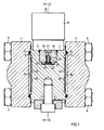
- FIG. 1 and 2 of a pressure difference measuring device has a pressure receiving body 1, which is covered on its two end faces 2 and 3 by housing caps 4 and 5.
- the measuring instrument is connected to the medium via invisible openings in the housing caps, the Pressure difference to be recorded.
- the pressure receiving body 1 and the housing caps 4 and 5 are clamped together by means of bolts 6 and 7 and nuts 8 and 9.
- a housing 10 in which the electronic circuit of the measuring device or parts of the circuit are accommodated;
- the housing 10 is only shown in its outer outline in the figures.
- the housing caps 4 and 5 are each pressed onto the pressure-receiving body 1 via a sealing ring 11 and 12.
- the pressure receiving body 1 is formed on its two end faces 2 and 3 so that a membrane bed 13 and 14 is formed there. With the pressure receiving body 1 an auxiliary membrane is connected to the two end faces 2 and 3 are respectively 15 and 16 are welded, wherein the additional membranes 15 and 1 6 each having such a bias that they are pressed against the respective membrane bed 13 and 14 respectively.
- a separating membrane 17 and 18 is also attached to each of the end faces 2 and 3 of the pressure receiving body 1.
- the additional membranes 15 and 16 are made smaller in diameter than the separating membranes 17 and 18.
- the pressure receiving body 1 has a pot-like recess 19 in the peripheral region between the membranes, which in the exemplary embodiment shown has a further recess 20 with smaller dimensions towards the inside of the pressure receiving body 1.
- a support body 21 of a semiconductor pressure sensor 22 is inserted into the pot-like recess 19.
- the support body 21 is provided with a longitudinal bore 23 which is welded at the top and in which a tube 25 is held by means of a glass melt 24.
- This tube 25 protrudes somewhat from the support body 21 downward from the longitudinal bore 23.
- the semiconductor pressure sensor 22 is hermetically sealed, which can be a semiconductor pressure sensor with a known structure (see, for example, DE-OS 2617731).
- the support body 21 has a transverse bore 26 which extends from the longitudinal bore 23 to the edge of the support body 21.
- the transverse bore 26 opens into a pressure-transmitting channel 27 in the pressure receiving body 1.
- the pressure-transmitting channel 27 forms, together with the transverse bore 26 and a channel piece 28, a connecting channel 29 which is continued from the upper side of the semiconductor pressure sensor 22 in the figures; to the outside, the connecting channel 29 is sealed by a ball seal 30.
- the support body 21 is firmly connected to the pressure receiving body 1 at its outer edge by means of a welded connection 31.
- the position of the transverse bore 26 and the design of the welded connection 31 ensure that in the region of the transition point from the transverse bore 26 to the pressure-transmitting channel 27, a seal is created around the transition point, leaving a passage opening free. Therefore, the pressure in the pressure-transmitting channel 27 cannot undesirably pass along the cylindrical parting line between the supporting body 21 and the pressure-receiving body 1 to the lower side of the semiconductor pressure sensor 22, which lies in the further recess 20. This is because a further pressure-transmitting channel 32 opens into this further recess 20.
- the further pressure-transmitting channel 32 is connected to a further channel piece 33 which, with the further pressure-transmitting channel 32, forms a further connecting channel 34 which is sealed off from the outside by a further ball 35, by pressing the two balls 30 and 35 against their sealing point via a pressure piece 36 and a threaded bolt 37.
- Both connecting channels 29 and 34 lie in the same plane, which represents a parallel plane to the end faces 2 and 3 of the pressure receiving body 1.
- each with two separating membranes 17 and 18 and two additional membranes 15 and 16 a branch channel and a further branch channel depart from the connecting channels 29 and 34, of which only one branch channel 38 and one further branch channel 39 are shown in FIG. 2 is recognizable.
- the one branch channel 38 leads to the separating membrane 17 and the further branch channel 39 leads to the additional membrane 15 on one and the same end face 2 of the pressure-receiving body 1.
- Another branch channel leads from the connecting channel 29 to the additional membrane 16 and an additional (also not shown) Branch channel from the further connecting channel 34 to the separating membrane 18. All channels in the interior of the pressure receiving body 1 as well as the transverse bore 26 and the further recess 20 are filled with a pressure transmission liquid.
- a compensation membrane 40 is attached in the recess 20 of the pressure-receiving body 1 by being welded to the bottom 41 of the recess 20 at its edge in a manner not shown. Below the compensating membrane 40 there is a free space 42 filled with pressure transmission liquid, which allows the compensating membrane 40 to be deflected. An additional channel 43, which leads to the one connecting channel 29, opens into this free space 4 2.
- the compensation membrane 40 is therefore arranged parallel to the semiconductor pressure sensor 22.
- damping element 44 and 45 in each connecting channel 29 and 34, respectively at a point between the semiconductor pressure sensor 22 and the outlets of the branch channels 38 and 39.
- the pressure transmission fluid within the pressure receiving body 1 and thus also in the area between the damping elements 44 and 45 and the semiconductor pressure sensor 22 is compressed as a result of the static pressure. If the static pressure suddenly drops, then the pressure transmission liquid in the pressure receiving body 1 expands and therefore also in the area between the damping elements 44 and 45 and the semiconductor pressure sensor 22. Because the volume of the pressure transmission fluid on both sides of the semiconductor pressure sensor 22 is generally of different sizes, this expansion of the pressure transmission fluid could result in a pressure difference which is harmful to the semiconductor pressure sensor 22. However, to such a dangerously high pressure differential does not occur with the meter, because this is prevented by the compensating diaphragm 4 0 whose rigidity than that of the auxiliary membrane is greater than 16 and 17 and smaller than that of the semiconductor pressure sensor 22nd
Landscapes
- Physics & Mathematics (AREA)
- General Physics & Mathematics (AREA)
- Measuring Fluid Pressure (AREA)
Applications Claiming Priority (2)
| Application Number | Priority Date | Filing Date | Title |
|---|---|---|---|
| DE3443419 | 1984-11-26 | ||
| DE19843443419 DE3443419A1 (de) | 1984-11-26 | 1984-11-26 | Druckdifferenz-messgeraet mit einem halbleiter-drucksensor |
Publications (1)
| Publication Number | Publication Date |
|---|---|
| EP0183640A1 true EP0183640A1 (fr) | 1986-06-04 |
Family
ID=6251391
Family Applications (1)
| Application Number | Title | Priority Date | Filing Date |
|---|---|---|---|
| EP85730152A Withdrawn EP0183640A1 (fr) | 1984-11-26 | 1985-11-18 | Appareil de mesure d'une pression différentielle, comportant un élément semi-conducteur sensible à la pression |
Country Status (9)
| Country | Link |
|---|---|
| US (1) | US4637257A (fr) |
| EP (1) | EP0183640A1 (fr) |
| JP (1) | JPS61130839A (fr) |
| AU (1) | AU570394B2 (fr) |
| DE (1) | DE3443419A1 (fr) |
| ES (1) | ES8609706A1 (fr) |
| FI (1) | FI854649A7 (fr) |
| IN (1) | IN162349B (fr) |
| NO (1) | NO854351L (fr) |
Cited By (1)
| Publication number | Priority date | Publication date | Assignee | Title |
|---|---|---|---|---|
| WO2022128399A1 (fr) * | 2020-12-14 | 2022-06-23 | Endress+Hauser SE+Co. KG | Transducteur de pression coplanaire pour détermination de valeur de mesure de pression d'un milieu |
Families Citing this family (6)
| Publication number | Priority date | Publication date | Assignee | Title |
|---|---|---|---|---|
| USD297314S (en) | 1985-07-15 | 1988-08-23 | Rosemount Inc. | Pressure transmitter housing |
| DE10030838A1 (de) * | 1999-07-05 | 2001-01-11 | Luk Lamellen & Kupplungsbau | Verfahren zur Versorgung eines eine Getriebesteuerung aufweisenden Automatik-Getriebes und Automatik-Getriebe |
| DE102008054991A1 (de) * | 2008-12-19 | 2010-06-24 | Endress + Hauser Gmbh + Co. Kg | Differenzdruckmessumformer |
| DE102012202038A1 (de) * | 2012-02-10 | 2013-08-14 | Rolls-Royce Deutschland Ltd & Co Kg | Messvorrichtung mit einem Drucksensor |
| US8701496B1 (en) * | 2013-02-27 | 2014-04-22 | Honeywell International Inc. | Systems and methods for a pressure sensor having a two layer die structure |
| DE102017127138A1 (de) * | 2017-11-17 | 2019-05-23 | Endress+Hauser SE+Co. KG | Druckmessaufnehmer |
Citations (4)
| Publication number | Priority date | Publication date | Assignee | Title |
|---|---|---|---|---|
| GB1558770A (en) * | 1977-05-10 | 1980-01-09 | Bell & Howell Ltd | Differential pressure transducers |
| GB2086587A (en) * | 1980-11-03 | 1982-05-12 | Teltov Geraete Regler | Electrical fluid pressure transducers |
| GB2091883A (en) * | 1981-01-24 | 1982-08-04 | Skil Controls Ltd | Differential pressure transducer |
| US4452069A (en) * | 1980-12-26 | 1984-06-05 | Nippon Soken, Inc. | Method of and apparatus for sensing knocking in internal combustion engine |
Family Cites Families (8)
| Publication number | Priority date | Publication date | Assignee | Title |
|---|---|---|---|---|
| DE347276C (de) * | 1919-07-26 | 1922-01-12 | Farbenfab Vorm Bayer F & Co | Verfahren zum Drucken von Pigmenten auf Textilgeweben mit Acetylcellulose als Fixierungsmittel |
| IT1025881B (it) * | 1974-11-21 | 1978-08-30 | Nuovo Pignone Spa | Sistema di protezione alle sovra pressioni di un sensore a wafer di siligio di un trasmettitore di pressione differenziale |
| DE2712846A1 (de) * | 1976-03-24 | 1977-11-24 | Ict Instr Inc | Messumformer zum messen von druckunterschieden |
| US4135407A (en) * | 1978-04-03 | 1979-01-23 | The Foxboro Company | Method and apparatus for overrange protection of the transducer in a differential pressure transmitter |
| DE3222620A1 (de) * | 1982-02-15 | 1983-08-25 | Siemens AG, 1000 Berlin und 8000 München | Druck- oder druckdifferenzmessgeraet mit einer vor ueberlastung geschuetzten drucksonsor-einrichtung |
| US4527428A (en) * | 1982-12-30 | 1985-07-09 | Hitachi, Ltd. | Semiconductor pressure transducer |
| JPS59203936A (ja) * | 1983-05-04 | 1984-11-19 | Hitachi Ltd | 半導体差圧発信器 |
| US4563901A (en) * | 1983-09-09 | 1986-01-14 | International Telephone & Telegraph Corp. | Transducer |
-
1984
- 1984-11-26 DE DE19843443419 patent/DE3443419A1/de not_active Withdrawn
-
1985
- 1985-10-31 NO NO854351A patent/NO854351L/no unknown
- 1985-11-15 US US06/798,564 patent/US4637257A/en not_active Expired - Fee Related
- 1985-11-18 IN IN816/CAL/85A patent/IN162349B/en unknown
- 1985-11-18 EP EP85730152A patent/EP0183640A1/fr not_active Withdrawn
- 1985-11-22 JP JP60263608A patent/JPS61130839A/ja active Pending
- 1985-11-25 FI FI854649A patent/FI854649A7/fi not_active Application Discontinuation
- 1985-11-25 AU AU50317/85A patent/AU570394B2/en not_active Expired - Fee Related
- 1985-11-25 ES ES549254A patent/ES8609706A1/es not_active Expired
Patent Citations (4)
| Publication number | Priority date | Publication date | Assignee | Title |
|---|---|---|---|---|
| GB1558770A (en) * | 1977-05-10 | 1980-01-09 | Bell & Howell Ltd | Differential pressure transducers |
| GB2086587A (en) * | 1980-11-03 | 1982-05-12 | Teltov Geraete Regler | Electrical fluid pressure transducers |
| US4452069A (en) * | 1980-12-26 | 1984-06-05 | Nippon Soken, Inc. | Method of and apparatus for sensing knocking in internal combustion engine |
| GB2091883A (en) * | 1981-01-24 | 1982-08-04 | Skil Controls Ltd | Differential pressure transducer |
Cited By (1)
| Publication number | Priority date | Publication date | Assignee | Title |
|---|---|---|---|---|
| WO2022128399A1 (fr) * | 2020-12-14 | 2022-06-23 | Endress+Hauser SE+Co. KG | Transducteur de pression coplanaire pour détermination de valeur de mesure de pression d'un milieu |
Also Published As
| Publication number | Publication date |
|---|---|
| IN162349B (fr) | 1988-05-07 |
| JPS61130839A (ja) | 1986-06-18 |
| FI854649A7 (fi) | 1986-05-27 |
| ES8609706A1 (es) | 1986-07-16 |
| US4637257A (en) | 1987-01-20 |
| AU570394B2 (en) | 1988-03-10 |
| FI854649A0 (fi) | 1985-11-25 |
| DE3443419A1 (de) | 1986-05-28 |
| ES549254A0 (es) | 1986-07-16 |
| NO854351L (no) | 1986-05-27 |
| AU5031785A (en) | 1986-06-05 |
Similar Documents
| Publication | Publication Date | Title |
|---|---|---|
| EP0086737B1 (fr) | Dispositif de mesure de pression ou de différence de pression avec un capteur de mesure protégé contre les surpressions | |
| DE4042411C2 (de) | Kapazitiver Differenzdruckdetektor | |
| DE19608321C2 (de) | Differenzdruckmeßumformereinheit mit einem Überlastschutzsystem | |
| DE102009055149A1 (de) | Überlastsicherer, Drucksensor, insbesondere Differenzdrucksensor | |
| WO1994021992A1 (fr) | Convertisseur de mesure de pression differentielle | |
| EP2359098B1 (fr) | Convertisseur de mesure de pression différentielle | |
| EP0276889B1 (fr) | Capteur de pression pour charges de pression statiques avec corps en silicium | |
| DE2819303A1 (de) | Druckfuehleinrichtung | |
| DE19608310C1 (de) | Differenzdruckmeßumformereinheit mit einem Überlastschutzsystem | |
| DE2640235A1 (de) | Differenzdruck-messeinrichtung | |
| DE102006057828A1 (de) | Differenzdruckmeßaufnehmer | |
| EP0115074B1 (fr) | Dispositif de mesure de pression différentielle | |
| EP0183640A1 (fr) | Appareil de mesure d'une pression différentielle, comportant un élément semi-conducteur sensible à la pression | |
| DE4211816A1 (de) | Drucksensor und Verfahren zu seiner Herstellung | |
| EP0157726B1 (fr) | Dispositif de mesure de pression ou de différence de pression | |
| DE10105230A1 (de) | Differenzdrucksensor mit Überlastsicherung | |
| EP1269136A1 (fr) | Capteur de pression differentielle | |
| DE2825222C2 (de) | Druckmeßumformer | |
| DE19709846C1 (de) | Druckdifferenz-Meßumformer | |
| DE2854262A1 (de) | Differenzdruck-messeinrichtung | |
| DE3236720C2 (fr) | ||
| DE4338558C1 (de) | Gerät zur Messung von Differenzdruck | |
| DE3341987A1 (de) | Ueberdrucksicherung fuer eine differenzdruckmesszelle | |
| DE102004047419B4 (de) | Druckmittler und Drucksensor mit Druckmittler | |
| EP0157990B1 (fr) | Machine électrique |
Legal Events
| Date | Code | Title | Description |
|---|---|---|---|
| PUAI | Public reference made under article 153(3) epc to a published international application that has entered the european phase |
Free format text: ORIGINAL CODE: 0009012 |
|
| AK | Designated contracting states |
Kind code of ref document: A1 Designated state(s): AT BE CH DE FR GB IT LI NL SE |
|
| STAA | Information on the status of an ep patent application or granted ep patent |
Free format text: STATUS: THE APPLICATION IS DEEMED TO BE WITHDRAWN |
|
| 18D | Application deemed to be withdrawn |
Effective date: 19861205 |
|
| RIN1 | Information on inventor provided before grant (corrected) |
Inventor name: VON RAUCH, MORIZ, ING. GRAD. |