EP0183643A1 - Système de mesure d'humidité dans des processus continus ou discontinus - Google Patents
Système de mesure d'humidité dans des processus continus ou discontinus Download PDFInfo
- Publication number
- EP0183643A1 EP0183643A1 EP85810491A EP85810491A EP0183643A1 EP 0183643 A1 EP0183643 A1 EP 0183643A1 EP 85810491 A EP85810491 A EP 85810491A EP 85810491 A EP85810491 A EP 85810491A EP 0183643 A1 EP0183643 A1 EP 0183643A1
- Authority
- EP
- European Patent Office
- Prior art keywords
- measuring cylinder
- measuring
- arrangement according
- piston
- moisture sensor
- Prior art date
- Legal status (The legal status is an assumption and is not a legal conclusion. Google has not performed a legal analysis and makes no representation as to the accuracy of the status listed.)
- Withdrawn
Links
- 238000000034 method Methods 0.000 title claims abstract description 17
- 239000007787 solid Substances 0.000 claims abstract description 8
- 230000000694 effects Effects 0.000 claims description 13
- XLYOFNOQVPJJNP-UHFFFAOYSA-N water Substances O XLYOFNOQVPJJNP-UHFFFAOYSA-N 0.000 claims description 13
- 238000010924 continuous production Methods 0.000 claims description 4
- 238000010923 batch production Methods 0.000 claims description 2
- 239000000463 material Substances 0.000 abstract description 19
- 238000000265 homogenisation Methods 0.000 abstract description 3
- 238000005259 measurement Methods 0.000 description 15
- 238000001035 drying Methods 0.000 description 4
- 239000013590 bulk material Substances 0.000 description 2
- 230000009286 beneficial effect Effects 0.000 description 1
- 230000001419 dependent effect Effects 0.000 description 1
- 238000005485 electric heating Methods 0.000 description 1
- 238000005265 energy consumption Methods 0.000 description 1
- 230000003203 everyday effect Effects 0.000 description 1
- 238000010438 heat treatment Methods 0.000 description 1
- 238000009434 installation Methods 0.000 description 1
- 238000009413 insulation Methods 0.000 description 1
- 238000011835 investigation Methods 0.000 description 1
- 239000002184 metal Substances 0.000 description 1
- 239000000843 powder Substances 0.000 description 1
- 230000001360 synchronised effect Effects 0.000 description 1
Images
Classifications
-
- G—PHYSICS
- G01—MEASURING; TESTING
- G01N—INVESTIGATING OR ANALYSING MATERIALS BY DETERMINING THEIR CHEMICAL OR PHYSICAL PROPERTIES
- G01N1/00—Sampling; Preparing specimens for investigation
- G01N1/02—Devices for withdrawing samples
- G01N1/10—Devices for withdrawing samples in the liquid or fluent state
- G01N1/20—Devices for withdrawing samples in the liquid or fluent state for flowing or falling materials
-
- G—PHYSICS
- G01—MEASURING; TESTING
- G01N—INVESTIGATING OR ANALYSING MATERIALS BY DETERMINING THEIR CHEMICAL OR PHYSICAL PROPERTIES
- G01N27/00—Investigating or analysing materials by the use of electric, electrochemical, or magnetic means
- G01N27/02—Investigating or analysing materials by the use of electric, electrochemical, or magnetic means by investigating impedance
- G01N27/04—Investigating or analysing materials by the use of electric, electrochemical, or magnetic means by investigating impedance by investigating resistance
- G01N27/048—Investigating or analysing materials by the use of electric, electrochemical, or magnetic means by investigating impedance by investigating resistance for determining moisture content of the material
Definitions
- the invention relates to an arrangement for measuring the water activity on bulk goods or other solids according to the preamble of claim 1.
- the object of the invention is therefore to enable reliable and reproducible measurement of the water activity on bulk materials or other solids with the known moisture sensors.
- the invention is based on the knowledge that not only the quality of the moisture sensor is decisive for a reliable water activity measurement, but also the quality of the measuring point has a decisive influence on the measurement result. To do this, a homogeneous distribution and even transport of the measured material must always be guaranteed. As mentioned at the beginning, this can only be achieved in a secondary branch of the continuous or batch process, in which the homogenization of the material to be measured is consciously carried out.
- the measuring arrangement according to the invention has the enormous advantage that it is small in size in order to obtain an accurate water activity measurement. Therefore, only a small part of the bulk material or the solid needs to be branched off.
- a drying system e.g. About a bucket full of measuring material every day.
- the delivery fork in the collecting tube and the conical end of the measuring cylinder prevent the material to be stuck, even with particularly moist materials. This is of importance for an economical energy consumption of the drying plant.
- the end cover at the end of the measuring cylinder also contributes to the homogenization of the material to be measured.
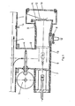
- FIG. 1 The arrangement shown in FIG. 1 is provided as a secondary branch of a continuous process.
- a small part of a bulk material or other solid 2 (the measured material) is branched off from a main branch 1 of the process into a collecting duct 3.
- Two delivery forks 4 in the collecting duct 3 ensure that the material to be measured 2 does not jam. They are moved back and forth by an eccentric drive 5, which consists of a circular disk driven by an electric motor with an eccentric fastening for the conveyor fork 4. Then the sample falls into a measuring cylinder 6 on which the collecting duct 3 is located.
- a piston 7 in the measuring cylinder 6 moves the material to be measured 2 to a humidity sensor 8, here a combination of a conductivity humidity sensor and a temperature sensor.
- the F Vietnameseteenler 8 is mounted in the wall of the measuring cylinder 6 and is located outside the sliding range of the piston 7.
- the piston 7 is driven by a - driven linear electric motor - not shown.
- the movements of the feed fork 4 and the piston 7 are synchronized by an electronic circuit (not shown).
- the inner wall of the measuring cylinder 6 is conical at its end 9.
- the half-shell of a cylinder cut lengthways can also be pressed into the measuring cylinder 6. This prevents moist material 2 with a water activity a greater than 0.75 from getting stuck in the measuring cylinder.
- the conical end 9 of the measuring cylinder 6 opens into a collecting container 10 and is provided with an end cover 11 which is pressed against the conical end 9 by a leaf spring.
- the piston 7 and the end cover 11 cause the measured material 2 to be pushed along the moisture sensor 8 in a very homogeneously distributed state.
- the measuring cylinder 6 is surrounded by an electrical heater, which consists of an insulation mat interspersed with metal wire.
- an electrical heater which consists of an insulation mat interspersed with metal wire.
- the main branch 1 there is a temperature sensor 14 which, together with the temperature sensor for the humidity sensor 8, emits temperature signals to an electronic control circuit (not shown here). Due to the difference between the two temperature signals, the electrical heating is switched on by the control circuit. It should be noted that the temperature in the main branch 1 is always greater than or equal to the temperature in the secondary branch. If the temperature signals are the same, the electronic control circuit switches the electric heater 13 off again. This ensures that the measuring temperature is always the same as the process temperature and reproducible water activity measurements are given in the measuring cylinder 6.
- the collecting channel 3 can have a cylindrical or rectangular profile.
- the collecting duct has a rectangular average of 65 x 38 mm.
- the stroke of the piston 7 in the measuring cylinder 6 is 300 mm.
- the inside diameter of the measuring cylinder 6 is 63 mm.
- the stroke time is adjustable from a minimum of 25 seconds to 25 minutes. Since the dimensions of the entire arrangement compared to the conventional systems, e.g. to the infrared or microwave measuring method, are particularly low, the installation in any process is unproblematic. The small dimensions, on the other hand, result in a small output of measured material 2, so that the measured material 2 can either be returned to the process in a simple manner or can be dispensed with entirely.
- a manual control is provided in order to check and set the correct functional sequence of the entire arrangement - in particular the synchronization of the movements of the delivery fork 4 and the piston 7 and the stroke time of the piston 7.
- the arrangement has proven particularly useful for bulk goods, e.g. in various granulating and drying plants.
- the use of the arrangement described is not limited to this. It will also be beneficial in water activity measurement in processes with other solids, e.g. with floury powders.
Landscapes
- Life Sciences & Earth Sciences (AREA)
- Chemical & Material Sciences (AREA)
- Analytical Chemistry (AREA)
- Physics & Mathematics (AREA)
- Health & Medical Sciences (AREA)
- Biochemistry (AREA)
- General Health & Medical Sciences (AREA)
- General Physics & Mathematics (AREA)
- Immunology (AREA)
- Pathology (AREA)
- Electrochemistry (AREA)
- Chemical Kinetics & Catalysis (AREA)
- Hydrology & Water Resources (AREA)
- Investigating Or Analyzing Materials By The Use Of Electric Means (AREA)
Applications Claiming Priority (2)
| Application Number | Priority Date | Filing Date | Title |
|---|---|---|---|
| CH511884 | 1984-10-28 | ||
| CH5118/84 | 1984-10-28 |
Publications (1)
| Publication Number | Publication Date |
|---|---|
| EP0183643A1 true EP0183643A1 (fr) | 1986-06-04 |
Family
ID=4288227
Family Applications (1)
| Application Number | Title | Priority Date | Filing Date |
|---|---|---|---|
| EP85810491A Withdrawn EP0183643A1 (fr) | 1984-10-28 | 1985-10-28 | Système de mesure d'humidité dans des processus continus ou discontinus |
Country Status (1)
| Country | Link |
|---|---|
| EP (1) | EP0183643A1 (fr) |
Cited By (4)
| Publication number | Priority date | Publication date | Assignee | Title |
|---|---|---|---|---|
| EP0571115A3 (en) * | 1992-05-19 | 1994-08-24 | Tdk Corp | A humidity meter |
| DE19744485A1 (de) * | 1997-10-09 | 1999-04-15 | Claas Selbstfahr Erntemasch | Vorrichtung zur Feuchtemessung in Erntemaschinen |
| DE102005001850A1 (de) * | 2005-01-10 | 2006-07-20 | Ese Embedded System Engineering Gmbh | Messeinrichtung |
| EP4710748A1 (fr) * | 2024-09-16 | 2026-03-18 | CLAAS Selbstfahrende Erntemaschinen GmbH | Moissonneuse-batteuse automotrice |
Citations (5)
| Publication number | Priority date | Publication date | Assignee | Title |
|---|---|---|---|---|
| US2836069A (en) * | 1955-09-01 | 1958-05-27 | Standard Oil Co | Sampling and metering device for fluent solid materials |
| US3270279A (en) * | 1964-02-07 | 1966-08-30 | Samuel Jackson Mfg Corp | Method and apparatus for determining the moisture content of cotton by sampling witha suction |
| US3339700A (en) * | 1965-09-24 | 1967-09-05 | Armstrong Cork Co | Sampling apparatus |
| CH471383A (de) * | 1968-05-24 | 1969-04-15 | Sina Ag | Einrichtung zur periodisch sich wiederholenden Feuchtigkeitsmessung eines Schüttgutes |
| DE2357062A1 (de) * | 1973-11-15 | 1975-05-22 | Ulrich Walter Maschinen Gmbh | Verfahren und vorrichtung zum entnehmen einer probe aus einer foerderleitung |
-
1985
- 1985-10-28 EP EP85810491A patent/EP0183643A1/fr not_active Withdrawn
Patent Citations (5)
| Publication number | Priority date | Publication date | Assignee | Title |
|---|---|---|---|---|
| US2836069A (en) * | 1955-09-01 | 1958-05-27 | Standard Oil Co | Sampling and metering device for fluent solid materials |
| US3270279A (en) * | 1964-02-07 | 1966-08-30 | Samuel Jackson Mfg Corp | Method and apparatus for determining the moisture content of cotton by sampling witha suction |
| US3339700A (en) * | 1965-09-24 | 1967-09-05 | Armstrong Cork Co | Sampling apparatus |
| CH471383A (de) * | 1968-05-24 | 1969-04-15 | Sina Ag | Einrichtung zur periodisch sich wiederholenden Feuchtigkeitsmessung eines Schüttgutes |
| DE2357062A1 (de) * | 1973-11-15 | 1975-05-22 | Ulrich Walter Maschinen Gmbh | Verfahren und vorrichtung zum entnehmen einer probe aus einer foerderleitung |
Cited By (8)
| Publication number | Priority date | Publication date | Assignee | Title |
|---|---|---|---|---|
| EP0571115A3 (en) * | 1992-05-19 | 1994-08-24 | Tdk Corp | A humidity meter |
| US5396796A (en) * | 1992-05-19 | 1995-03-14 | Tdk Corporation | Humidity meter |
| DE19744485A1 (de) * | 1997-10-09 | 1999-04-15 | Claas Selbstfahr Erntemasch | Vorrichtung zur Feuchtemessung in Erntemaschinen |
| US6155103A (en) * | 1997-10-09 | 2000-12-05 | Claas Selbstfahrende Erntemaschinen Gmbh | Device for moisture measurement in harvesting machines |
| US6327899B1 (en) | 1997-10-09 | 2001-12-11 | Claas Selbstfahrende Erntemaschinen Gmbh | Device for moisture measurement in harvesting machines |
| DE102005001850A1 (de) * | 2005-01-10 | 2006-07-20 | Ese Embedded System Engineering Gmbh | Messeinrichtung |
| DE102005001850B4 (de) * | 2005-01-10 | 2007-11-15 | Ese Embedded System Engineering Gmbh | Messeinrichtung und Verfahren zum Messen einer Größe einer Flüssigkeit |
| EP4710748A1 (fr) * | 2024-09-16 | 2026-03-18 | CLAAS Selbstfahrende Erntemaschinen GmbH | Moissonneuse-batteuse automotrice |
Similar Documents
| Publication | Publication Date | Title |
|---|---|---|
| DE3502546C2 (de) | Analysengerät zur Messung flüssiger oder gasförmiger Proben | |
| EP0819248A1 (fr) | Capteur d'humidite | |
| DE3502095C2 (fr) | ||
| EP1348108A1 (fr) | Procede et dispositif de mesure de niveaux | |
| DE2552820A1 (de) | Geraet zur sequentiellen entnahme von luftproben | |
| DE2018068C3 (fr) | ||
| EP3108968A1 (fr) | Dispositif de determination du niveau de colle fondue dans un recipient | |
| DE2265237A1 (de) | Vorrichtung zur pruefung der wandstaerke von rohren aus nicht leitendem material | |
| EP0183643A1 (fr) | Système de mesure d'humidité dans des processus continus ou discontinus | |
| DE69000915T2 (de) | Sich hin- und herbewegende ueberfuehrungsvorrichtung. | |
| DE3707561A1 (de) | Verfahren zur schnellen bestimmung des feuchtigkeitsgehaltes von zersetzlichem messgut und vorrichtung zur durchfuehrung des verfahrens | |
| EP0151781A2 (fr) | Procédé et dispositif de mise en température d'un liquide à analyser et de réactifs nécessaires à l'analyse | |
| EP1358464B1 (fr) | Procédé pour la production d'échantillons de cendre de filtres ou de cendre volante | |
| DE3818697C2 (fr) | ||
| DE19758356A1 (de) | Modulares Vielkanalprobenahme- und Meßsystem zur automatischen Langzeitanalyse von Fluiden für hydrogeologische Feld- und Laborversuche | |
| DE102007058390A1 (de) | Vorrichtung und Verfahren zur thermogravimetrischen Materialfeuchtebestimmung | |
| DE4009112C2 (de) | Vorrichtung zur Herstellung einer trockenen schichtartigen Probe von Feststoffteilchen aus einer Suspension | |
| EP2574902A1 (fr) | Appareil de mesure destiné à la détermination de l'humidité gravimétrique | |
| DE2641801A1 (de) | Geraet zur automatischen entnahme von proben von wasser und abwaessern und sonstigen fluessigkeiten | |
| CH690510A5 (de) | In einem Gehäuse eingebauter Trockner. | |
| EP0628330A1 (fr) | Evaporateur rotatif | |
| DE19610599C2 (de) | Feuchtesensor | |
| EP2574901A1 (fr) | Appareil de mesure destiné à la détermination de l'humidité gravimétrique | |
| DE4001406C2 (fr) | ||
| DE2522256A1 (de) | Selbsttaetige vorrichtung zur bestimmung der rauchdichte |
Legal Events
| Date | Code | Title | Description |
|---|---|---|---|
| PUAI | Public reference made under article 153(3) epc to a published international application that has entered the european phase |
Free format text: ORIGINAL CODE: 0009012 |
|
| AK | Designated contracting states |
Kind code of ref document: A1 Designated state(s): AT BE CH DE FR GB IT LI LU NL SE |
|
| RBV | Designated contracting states (corrected) |
Designated state(s): DE FR GB |
|
| 17P | Request for examination filed |
Effective date: 19870203 |
|
| RAP1 | Party data changed (applicant data changed or rights of an application transferred) |
Owner name: INTERSENSOR SA |
|
| 17Q | First examination report despatched |
Effective date: 19891110 |
|
| STAA | Information on the status of an ep patent application or granted ep patent |
Free format text: STATUS: THE APPLICATION IS DEEMED TO BE WITHDRAWN |
|
| 18D | Application deemed to be withdrawn |
Effective date: 19900321 |
|
| RIN1 | Information on inventor provided before grant (corrected) |
Inventor name: GROENINGER, KURD G., DR.-ING. |