EP0183658B1 - Système pour changer la surface d'une voile par enroulement - Google Patents
Système pour changer la surface d'une voile par enroulement Download PDFInfo
- Publication number
- EP0183658B1 EP0183658B1 EP85830295A EP85830295A EP0183658B1 EP 0183658 B1 EP0183658 B1 EP 0183658B1 EP 85830295 A EP85830295 A EP 85830295A EP 85830295 A EP85830295 A EP 85830295A EP 0183658 B1 EP0183658 B1 EP 0183658B1
- Authority
- EP
- European Patent Office
- Prior art keywords
- sail
- sheath
- coupling line
- along
- rolling
- Prior art date
- Legal status (The legal status is an assumption and is not a legal conclusion. Google has not performed a legal analysis and makes no representation as to the accuracy of the status listed.)
- Expired
Links
- 238000005096 rolling process Methods 0.000 claims description 27
- 230000008878 coupling Effects 0.000 claims description 16
- 238000010168 coupling process Methods 0.000 claims description 16
- 238000005859 coupling reaction Methods 0.000 claims description 16
- 230000000694 effects Effects 0.000 claims description 7
- 238000007493 shaping process Methods 0.000 claims description 7
- 239000004744 fabric Substances 0.000 description 7
- 230000015572 biosynthetic process Effects 0.000 description 3
- 230000035515 penetration Effects 0.000 description 3
- 238000004804 winding Methods 0.000 description 3
- 210000001015 abdomen Anatomy 0.000 description 1
- 238000004873 anchoring Methods 0.000 description 1
- 230000007717 exclusion Effects 0.000 description 1
- 235000013861 fat-free Nutrition 0.000 description 1
- 238000000034 method Methods 0.000 description 1
- 238000012986 modification Methods 0.000 description 1
- 230000004048 modification Effects 0.000 description 1
- 239000011295 pitch Substances 0.000 description 1
- 230000000750 progressive effect Effects 0.000 description 1
Images

Classifications
-
- B—PERFORMING OPERATIONS; TRANSPORTING
- B63—SHIPS OR OTHER WATERBORNE VESSELS; RELATED EQUIPMENT
- B63H—MARINE PROPULSION OR STEERING
- B63H9/00—Marine propulsion provided directly by wind power
- B63H9/04—Marine propulsion provided directly by wind power using sails or like wind-catching surfaces
- B63H9/08—Connections of sails to masts, spars, or the like
- B63H9/10—Running rigging, e.g. reefing equipment
- B63H9/1021—Reefing
- B63H9/1028—Reefing by furling around stays
Definitions
- the invention relates to a sail manoeuvrable through the rotation of a rolling and unrolling structure to which the sail is anchored along an anchorage edge.
- a roller furling sail i.e. a sail which can be reduced in surface by rolling it up on the structure to which said sail is anchored, is known from US-A 4 449 467.
- this known sail there are used at least two different sail cloth weights, said sail being constructed so that as the sail is furled, it is predomi- nently the lightest weight cloth that is the first cloth to be taken up, leaving a greater percentage of the heavier cloth exposed to the wind action. During its manoeuvring, the sail remains flat.
- a sail rolling up device having a tubular element on which the sail can be wound up in order to reduce its area.
- the groove on the tubular element which receives the anchoring edge of the sail is formed by two helixes with variable and reverse pitches, and which join up towards the middle of said tubular element.
- This known solution has several drawbacks.
- the formation of the shaped groove is rather complicated and expensive.
- the belly of the sail which can be taken up depends on the shape of the groove. Therefore only one sail shaping can be correctly used for each tubular element. High turbolences are generated near the said tubular element, said turbolences reducing the efficiency of the sail.
- the invention has the purpose to reconcile the two requirements of fat-sail attitude and rolling capability, by taking into account that the maximum exploitation of the wind is obviously required, above all, with poor winds, and thus in conditions of the greatest extension of the sail for the maximum exploitation of the aeolian or wind energy, while the reduction of the sail area is carried out in presence of an excess of wind energy and, therefore, in the conditions under which the maximum exploitation of the wind is not important.
- a further object of the invention is to accomplish, in combination with the above requirements, the best outline of the sail structure with the purpose of the sail penetration and the exploitation of an additional dynamic thrust effect, for a phenomenon similar to the one obtainable with a typical wing outline which is present in the birds wing and in the wing of the flying machine.
- the invention ensures also the obtainment of such additional object which is the more effective and appropriate the larger the cross-section of the sail mounting and rolling straight structure is; the larger section of this rolling structure ensures a correct rolling without torsional effects along the development of the straight structure, what is possible with a reduced section in respect to a considerable linear development like that of sails having remarkable dimensions.
- a sail according to the invention manoeuvrable by rotation of a rolling and unrolling structure to which the sail is anchored along an anchorage edge - comprises a sheath (or an equivalent structure) which surrounds said rolling structure and engages the sail at opposite sides along a coupling line spaced out from the anchorage edge; the edges of said sheath, the anchorage edge of said sail and said coupling line have such shapings that - in unwound condition - the sail stretches out retaining the sail strip comprised between the anchorage edge and the coupling line with the end zones non stretched and causing the sail to take a fat-sail arrangement; at the beginning of the rolling, the sail is called back onto the rolling structure along the intermediate zone and progressively also along the end zones and thus the sail takes up a flat- sail attitude.
- the rolling structure may be provided with relatively large section; the stretched condition of the sheath gives thus the sail a wing-like outline with dynamic effects of thrust and penetration.
- numeral 1 indicates a rectilinear cylindrical and mostly tubular rolling structure along which the anchorage edge of the sail is anchored like along a stay; said structure is capable of being rotated to roll the sail and to unroll and thus to stretch it in order either to exclude the sail or reduce its area.
- Structures of this kind are known for motorized manoeuvres on sails usually triangular.
- the rolling manoeuvre is feasible and is correctly performed only in presence of flat sails, whereas fat sails under condition of maximum extension of the sail are not suitable for a reduction or exclusion of the sail area by rolling, at least in conditions of correct rolling.
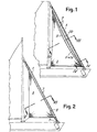
- a sail 3 is provided whose shaping corresponds to that of a flat sail.
- the sail anchorage edge, indicated by 3A, is engaged to the structure 1 to achieve the possibility of a correct winding.
- Numeral 5 indicates a coupling line parallel to and spaced out from the edge 3A, along which line 5, the edges 7A of a sheath 7 - especially made of sail fabric - are engaged to the sail 3, said sheath being arranged to partially wind up the structure 1 and cover the zone 3B developed as a strip of uniform width comprised between the coupling line 5 and the edge 3A of the sail 3; the mounting of the sheath 7 is carried out so as to permit its removal or its longitudinal opening.
- the strip 3B remains included within the sheath.
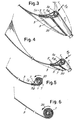
- the sheath 7 is dimensioned, in the intermediate cross sections, in such a way that the dimensions of the sheath section may correspond to the transverse dimensions of the strip 3B combined with the structure 1, thereby said strip 3B of sail 3 results, in the central zones, almost stretched inside the sheath 7, as indicated in Fig. 3, when the sail is affected by the wind.
- the same sheath 7 has cross-section dimensions gradually smaller, that is with shorter wings, since the edges 7A are arcuate; accordingly, the strip 3B of sail 3, in the zones that are closer to the ends, does not reach to stretch, but it remains slackened as shown by way of example in the drawing, while the two wings of sheath 7 remain stretched.
- the sail permits the maximum exploitation of the wind energy by behaving like a fat sail; moreover, the two branches of the sheath 7, which extend in stretched condition between the structure 1 and the connection line 5 of the edges 7A of the sail 3, make up, with the partial cylindrical outline of structure 1 (on which the sheath 7 centrally lies), a shaping having a wing outline section resembling the typical outline of the bird wind section; a thrust dynamic effect is thus introduced into the sail, while a greater penetration effect in the aeolian current is obtained when this affects the sail in a direction having at least a component according to arrow fX of Figs. 3 and 4.
- the sail 3 reaches and keeps its proper flat attitude and then winds up correctly on structure 1; the fabric of sheath 7 will progressively become imprisoned within the coils of sail 3 rolled up during the progressive formation of coils of the sail 3 above and outside of the line 5.
- the maximum stretching attitude of sail 3 will result arcuate like a fat sail depending on the shaping of the wings of sheath 7 and on the position of line 5, also with possible modifications in respect to the geometrical condition, stated above, of the line 5 being straight and parallel to the anchorage edge 3A, and of the edges 7A of sheath 7 being curved.
- the curvature of the edges 7A (or the curvature of other outlines functionally equivalent) will possibly be determined in relation to the fat-sail attitude which is to be imposed to the sail 3 in connection with the completely stretched sheath 7.
- the sail area made up of components 3 and 7 in the arrangement of maximum extension and, thus, of fat sail takes the wing outline, as indicated above, in both the dispositions that a sail assumes when veering and, accordingly, when the sail concavity overturns to appear on the face opposite to that previously concave as can be seen in Fig. 3, for comparison between the part shown with solid line and the part shown with chain dotted line.
- the strip 3B between the anchorage edge 3A and the coupling line 5 is provided with substantially constant width and the edges 7B of the sheath, which are mounted on the sail 3 along the coupling line 5, are, in this case, convex, so that the transverse dimensions of said sheath are greater at the centre than towards the ends.
- the strip 3B between the anchorage edge 3A and the coupling line 5 may be of lesser width at the centre than towards the ends, and the sheath 7 has, in this case, substantially constant dimensions.
- the strip 3B between the anchorage edge 3A and the coupling line 5 may be of lesser width at the centre than towards the ends, and the sheath 7 has, in this case, transverse dimensions greater at the centre than towards the ends.
- the sheath 7 can be opened along a closure means 20 to consent the removal of the sail 3 which may be thus pulled out along the structure 1 or otherwise disengaged from it.
Landscapes
- Engineering & Computer Science (AREA)
- Life Sciences & Earth Sciences (AREA)
- Sustainable Development (AREA)
- Sustainable Energy (AREA)
- Chemical & Material Sciences (AREA)
- Combustion & Propulsion (AREA)
- Mechanical Engineering (AREA)
- Ocean & Marine Engineering (AREA)
- Wind Motors (AREA)
- Soil Working Implements (AREA)
- Toys (AREA)
Claims (6)
Applications Claiming Priority (2)
| Application Number | Priority Date | Filing Date | Title |
|---|---|---|---|
| IT09554/84A IT1198972B (it) | 1984-11-30 | 1984-11-30 | Sistema per la modifica del profilo di una vela in avvolgimento per la riduzione della superficie |
| IT955484 | 1984-11-30 |
Publications (3)
| Publication Number | Publication Date |
|---|---|
| EP0183658A2 EP0183658A2 (fr) | 1986-06-04 |
| EP0183658A3 EP0183658A3 (en) | 1987-03-11 |
| EP0183658B1 true EP0183658B1 (fr) | 1989-05-03 |
Family
ID=11132117
Family Applications (1)
| Application Number | Title | Priority Date | Filing Date |
|---|---|---|---|
| EP85830295A Expired EP0183658B1 (fr) | 1984-11-30 | 1985-11-28 | Système pour changer la surface d'une voile par enroulement |
Country Status (9)
| Country | Link |
|---|---|
| US (1) | US4748926A (fr) |
| EP (1) | EP0183658B1 (fr) |
| JP (1) | JPS61135897A (fr) |
| AU (1) | AU581707B2 (fr) |
| DE (1) | DE3569914D1 (fr) |
| ES (1) | ES8700183A1 (fr) |
| FI (1) | FI80645C (fr) |
| IT (1) | IT1198972B (fr) |
| NZ (1) | NZ214388A (fr) |
Families Citing this family (3)
| Publication number | Priority date | Publication date | Assignee | Title |
|---|---|---|---|---|
| US5014637A (en) * | 1986-07-16 | 1991-05-14 | Stevenson William H Iv | Roller reefing system for sails and the like |
| US5315948A (en) * | 1991-10-08 | 1994-05-31 | Sail Systems, Inc. | Luff pad for roller reefing and furling sails |
| FI91620C (fi) * | 1993-04-28 | 1994-07-25 | Lasse Jaemsae | Kalvorakenne |
Family Cites Families (10)
| Publication number | Priority date | Publication date | Assignee | Title |
|---|---|---|---|---|
| US4196687A (en) * | 1978-02-03 | 1980-04-08 | Newick Richard C | Roller reefing system |
| FR2440870A1 (fr) * | 1978-11-07 | 1980-06-06 | Ingouf Pierre | Perfectionnement aux systemes enrouleurs de grand'voile |
| DE2934937A1 (de) * | 1979-08-29 | 1981-03-19 | Paul Dr. 1000 Berlin Mader | An einem mast anschlagbares segel |
| FR2515137B1 (fr) * | 1981-10-23 | 1985-12-20 | Maurin Suzanne | Dispositif enrouleur et emmagasineur de voile |
| GB2113636B (en) * | 1982-01-05 | 1986-02-05 | Robert Dennis Russell | Improved roller reefing systems for sails |
| DE3211641A1 (de) * | 1982-03-30 | 1983-10-06 | Franz Xaver Prof Dr I Wortmann | Segel mit profilnase |
| US4449467A (en) * | 1982-06-28 | 1984-05-22 | Hild Sails, Inc. | Variable weight cloth roller-furling sail |
| GB2133363B (en) * | 1983-01-13 | 1986-04-23 | Proengin | Reefing sails |
| AU3141084A (en) * | 1983-08-03 | 1985-02-07 | Michael Charles Barron | Sail housing |
| FR2557852B3 (fr) * | 1984-01-11 | 1986-02-21 | Bretagne Sarl Tech Voile | Dispositif de rattrapage de creux d'une voile qui s'enroule sur un enrouleur et voile qui en est equipee |
-
1984
- 1984-11-30 IT IT09554/84A patent/IT1198972B/it active
-
1985
- 1985-11-22 US US06/800,921 patent/US4748926A/en not_active Expired - Fee Related
- 1985-11-27 FI FI854698A patent/FI80645C/fi not_active IP Right Cessation
- 1985-11-28 DE DE8585830295T patent/DE3569914D1/de not_active Expired
- 1985-11-28 EP EP85830295A patent/EP0183658B1/fr not_active Expired
- 1985-11-28 ES ES549355A patent/ES8700183A1/es not_active Expired
- 1985-11-29 NZ NZ214388A patent/NZ214388A/en unknown
- 1985-11-29 JP JP60267586A patent/JPS61135897A/ja active Granted
- 1985-11-29 AU AU50595/85A patent/AU581707B2/en not_active Ceased
Also Published As
| Publication number | Publication date |
|---|---|
| FI854698L (fi) | 1986-05-31 |
| AU581707B2 (en) | 1989-03-02 |
| FI80645B (fi) | 1990-03-30 |
| AU5059585A (en) | 1986-06-05 |
| EP0183658A2 (fr) | 1986-06-04 |
| ES549355A0 (es) | 1986-10-01 |
| JPS61135897A (ja) | 1986-06-23 |
| EP0183658A3 (en) | 1987-03-11 |
| NZ214388A (en) | 1987-05-29 |
| ES8700183A1 (es) | 1986-10-01 |
| FI80645C (fi) | 1990-07-10 |
| FI854698A0 (fi) | 1985-11-27 |
| US4748926A (en) | 1988-06-07 |
| JPH0348080B2 (fr) | 1991-07-23 |
| IT8409554A0 (it) | 1984-11-30 |
| IT1198972B (it) | 1988-12-21 |
| DE3569914D1 (en) | 1989-06-08 |
Similar Documents
| Publication | Publication Date | Title |
|---|---|---|
| EP0865557B1 (fr) | Tente-parasol reglable | |
| KR930016634A (ko) | 블라인드(blind)의 서스펜젼코드(suspension cord)를 감는 장치 | |
| US4407317A (en) | Umbrella reversal prevention structure | |
| EP0155012A1 (fr) | Voile à lattes flexibles en forme d'aile portante | |
| US3611969A (en) | Jib-furling stay | |
| DE2658801A1 (de) | Reffvorrichtung fuer segelfahrzeuge | |
| DE68915311T2 (de) | Mast für Segelboot. | |
| US4573424A (en) | Sail shortening roller for sailing boats | |
| EP0183658A2 (fr) | Système pour changer la surface d'une voile par enroulement | |
| US5014637A (en) | Roller reefing system for sails and the like | |
| US4546718A (en) | Sailing ship | |
| DE2642570A1 (de) | Windkraftmaschine mit einem windrad | |
| WO2016150419A1 (fr) | Ensemble voile d'ombrage | |
| DE2348796A1 (de) | Sonnenschutzdach | |
| US4930434A (en) | Sail reducing winder | |
| AU771411B2 (en) | Furling sail system | |
| US4250826A (en) | Roller furling structure | |
| EP0064107A1 (fr) | Voilure rigide pour bateau et méthode pour replier cette voilure | |
| DE10144954A1 (de) | Energieerzeugungsanlage, insbesondere Windmühle | |
| DE3628475C2 (fr) | ||
| WO1987007234A1 (fr) | Ensemble de voile pourvu d'un organe de cambrure | |
| DE69510184T2 (de) | Verbesserte vorrichtung zum einholen und setzen von segeln | |
| NO131159B (fr) | ||
| US4751890A (en) | Boat sails mounted on winding booms | |
| CN120211610A (zh) | 一种用于百叶窗的卷带连接装置及百叶窗 |
Legal Events
| Date | Code | Title | Description |
|---|---|---|---|
| PUAI | Public reference made under article 153(3) epc to a published international application that has entered the european phase |
Free format text: ORIGINAL CODE: 0009012 |
|
| AK | Designated contracting states |
Kind code of ref document: A2 Designated state(s): DE FR GB |
|
| PUAL | Search report despatched |
Free format text: ORIGINAL CODE: 0009013 |
|
| AK | Designated contracting states |
Kind code of ref document: A3 Designated state(s): DE FR GB |
|
| 17P | Request for examination filed |
Effective date: 19870706 |
|
| 17Q | First examination report despatched |
Effective date: 19880224 |
|
| GRAA | (expected) grant |
Free format text: ORIGINAL CODE: 0009210 |
|
| AK | Designated contracting states |
Kind code of ref document: B1 Designated state(s): DE FR GB |
|
| REF | Corresponds to: |
Ref document number: 3569914 Country of ref document: DE Date of ref document: 19890608 |
|
| ET | Fr: translation filed | ||
| PLBE | No opposition filed within time limit |
Free format text: ORIGINAL CODE: 0009261 |
|
| STAA | Information on the status of an ep patent application or granted ep patent |
Free format text: STATUS: NO OPPOSITION FILED WITHIN TIME LIMIT |
|
| 26N | No opposition filed | ||
| REG | Reference to a national code |
Ref country code: GB Ref legal event code: 732E |
|
| REG | Reference to a national code |
Ref country code: FR Ref legal event code: TP |
|
| PGFP | Annual fee paid to national office [announced via postgrant information from national office to epo] |
Ref country code: FR Payment date: 19981027 Year of fee payment: 14 |
|
| PGFP | Annual fee paid to national office [announced via postgrant information from national office to epo] |
Ref country code: DE Payment date: 19981030 Year of fee payment: 14 |
|
| PGFP | Annual fee paid to national office [announced via postgrant information from national office to epo] |
Ref country code: GB Payment date: 19981204 Year of fee payment: 14 |
|
| PG25 | Lapsed in a contracting state [announced via postgrant information from national office to epo] |
Ref country code: GB Free format text: LAPSE BECAUSE OF NON-PAYMENT OF DUE FEES Effective date: 19991128 |
|
| GBPC | Gb: european patent ceased through non-payment of renewal fee |
Effective date: 19991128 |
|
| PG25 | Lapsed in a contracting state [announced via postgrant information from national office to epo] |
Ref country code: FR Free format text: LAPSE BECAUSE OF NON-PAYMENT OF DUE FEES Effective date: 20000731 |
|
| PG25 | Lapsed in a contracting state [announced via postgrant information from national office to epo] |
Ref country code: DE Free format text: LAPSE BECAUSE OF NON-PAYMENT OF DUE FEES Effective date: 20000901 |
|
| REG | Reference to a national code |
Ref country code: FR Ref legal event code: ST |