EP0183742B1 - Electronic switch - Google Patents
Electronic switch Download PDFInfo
- Publication number
- EP0183742B1 EP0183742B1 EP85902491A EP85902491A EP0183742B1 EP 0183742 B1 EP0183742 B1 EP 0183742B1 EP 85902491 A EP85902491 A EP 85902491A EP 85902491 A EP85902491 A EP 85902491A EP 0183742 B1 EP0183742 B1 EP 0183742B1
- Authority
- EP
- European Patent Office
- Prior art keywords
- electrode
- circuit
- input
- astable
- amplifier
- Prior art date
- Legal status (The legal status is an assumption and is not a legal conclusion. Google has not performed a legal analysis and makes no representation as to the accuracy of the status listed.)
- Expired - Lifetime
Links
- 239000003990 capacitor Substances 0.000 claims description 13
- 230000008859 change Effects 0.000 claims description 9
- 241000282414 Homo sapiens Species 0.000 claims description 8
- 241001465754 Metazoa Species 0.000 claims description 4
- 230000005855 radiation Effects 0.000 claims description 3
- 230000010355 oscillation Effects 0.000 abstract description 12
- 238000010168 coupling process Methods 0.000 description 5
- 238000005859 coupling reaction Methods 0.000 description 5
- 230000006870 function Effects 0.000 description 4
- 239000004020 conductor Substances 0.000 description 3
- 230000004913 activation Effects 0.000 description 2
- 230000003321 amplification Effects 0.000 description 2
- 230000000903 blocking effect Effects 0.000 description 2
- 230000008878 coupling Effects 0.000 description 2
- 230000000694 effects Effects 0.000 description 2
- 210000003811 finger Anatomy 0.000 description 2
- 239000002184 metal Substances 0.000 description 2
- 210000003205 muscle Anatomy 0.000 description 2
- 210000005036 nerve Anatomy 0.000 description 2
- 210000002569 neuron Anatomy 0.000 description 2
- 238000003199 nucleic acid amplification method Methods 0.000 description 2
- 230000008901 benefit Effects 0.000 description 1
- 230000003247 decreasing effect Effects 0.000 description 1
- 238000010586 diagram Methods 0.000 description 1
- 238000010616 electrical installation Methods 0.000 description 1
- 238000009434 installation Methods 0.000 description 1
- 238000009413 insulation Methods 0.000 description 1
- 230000001788 irregular Effects 0.000 description 1
- 238000004519 manufacturing process Methods 0.000 description 1
- 238000000034 method Methods 0.000 description 1
- 230000000474 nursing effect Effects 0.000 description 1
- 230000035479 physiological effects, processes and functions Effects 0.000 description 1
- 230000000284 resting effect Effects 0.000 description 1
- 230000035945 sensitivity Effects 0.000 description 1
- 210000003813 thumb Anatomy 0.000 description 1
- 230000001755 vocal effect Effects 0.000 description 1
Images
Classifications
-
- H—ELECTRICITY
- H03—ELECTRONIC CIRCUITRY
- H03K—PULSE TECHNIQUE
- H03K17/00—Electronic switching or gating, i.e. not by contact-making and –breaking
- H03K17/94—Electronic switching or gating, i.e. not by contact-making and –breaking characterised by the way in which the control signals are generated
- H03K17/96—Touch switches
- H03K17/962—Capacitive touch switches
Definitions
- Switches reacting to a light touch, have found a wide use connected with signal systems and electronic apparatus. Most of them work by direct pressure on a contact spring or on a flexible insulation plate covering the contact and may have an inscription, but it is also known to use electronic current circuits, which are effected by change of capacitance or by change of light reflection.
- a "touch” also can be a metal plate, the voltage of which is changed when it is touched, resulting in a change of the bias on a transistor electrode, as for example is disclosed in US Patent No. 3 766 404.
- One field of applications for such switches is learning apparatus and signal-and calling systems for disabled human beings, which only can move a few parts of the body, a thumb or the head.
- German Patent No. 3 029 717 is disclosed a touch contact with an oscillator, which when touching an electrode, which is connected to a frequency controlling L-C circuit, changes the amplitude of the oscillations.
- the oscillations are rectified and charge a capacitor, the voltage of which is used as a blocking voltage over a transistor comprising a relay in its current circuit.
- a touch responsive control circuit having a touch electrode and an astable amplifier which starts oscillation when, upon touching of the touch plate, the capacitive impedance of a human body is inserted into the feedback network.
- the present invention is based on a physiological phenomena, which makes it possible to distinguish between the influences of an elec- trdnic touch contact, which depends on a non- controllable change of the physical conditions of the environment (e.g. interference fields, changes of humidity degree of the air, change of temperature, change of capacitance, vibrations etc.) and the direct contact between a touch electrode and an unisolated part of a human or animal body.
- the outer potential changes which arise as a result of a nerve or muscle-fibres stimulus are of the same magnitude as those which are caused by disturbance fields from electronic installation, 10- 3 to 10- 4 volt, and are therefore not immediately useful for initiate a touch on an electrode.
- the positive voltage pulse i.e. the potential around the nerve cell
- the positive voltage pulse is short and is more negative than the resting potential.
- this phenomena it has been possible to use this phenomena as a unambiguous criterion of contacting an electrode by a finger or any other uninsulated part of a human or animal body.
- the electronic switch according to the invention is of the kind described in said German patent, in which contacting an input electrode of an electronic circuit changes its condition so that a relay will be activated, or a signal is generated.
- the invention is characterised in that the electronic circuit comprises an astable amplifier circuit with an input filter which is short-circuited by positive voltage changes but not for negative voltage changes and the output of which is connected to an aerial for emitting of resulted oscillations.
- the electronic switch according to the invention has no well-defined output voltage in the state of rest.
- the electronic switch according to the invention does not react on disturbance fields from electrical or electronic apparatus.
- touching the input electrode with a part of a human body arises an oscillation condition in MH z- range, which can be detected and activates a relay or generates a signal.
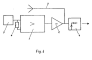
- Fig. 1 shows a schematic arrangement according to the invention.
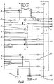
- Fig. 2 shows a more detailed embodiment of the invention.
- Fig. 1, 1 refers to an astable amplifier circuit and 2 refers to an amplifier which amplifies the output voltage of the generator before said output voltage is fed to an aerial 3 and an output stage 4 which converts a change of the output voltage from the generator to a current big enough to activate a relay or a signal lamp.
- the electrode 5 When the electrode 5 is untouched the voltage on the aerial is an undefined noise voltage. This condition is not changed by itself if strong interference sources, e.g. electric power lines or a television set, are placed close to the electrode 5. Only when the electrode 5 is directly touched by a part of a human body (or as said above by some part of any animal body) a pronounced change of the generator function takes place. Now the irregular noise voltage over the aerial is superimposed with a great pulsating voltage in the MH z - range.
- strong interference sources e.g. electric power lines or a television set
- the obtained effect can only depend on that the touching part of the body is included in a feedback circuit between the input and output of the generator and as a result of that modulates said generator.
- Fig. 2 is shown a detailed diagram for an electronic switch according to the invention.
- the amplifier 1 includes two amplifier circuits, namely one modified Darlington-coupling 7, with directly connected collectors, resulting in that the voltage over the collectors is constant, and two in a DC- manner directly connected transistors 22.
- the filter 6 in Fig. 1 includes here a big electrolytic capacitor in series with a potentiometer. This series connection is shunted with a big resistor 8. The sensitivity of the "touch" can be adjusted by means of the potentiometer. A resistor 9 sees to that there is sufficient positive bias on the input electrode of the Darlington coupling, that negative impulses can be transferred.
- An R-C filter 10 is inserted between the emitter of the first of the transistors 22 and the zero conductor.
- the direct connection between the collector of the first transistor and the base of the second transistor in the pair of transistors 22 gives such a big amplification that the amplifier becomes astable.
- Signals from the pair of transistors 22 are via a capacitor 13 transmitted to the output amplifier 2 (the same as 2 in Fig. 1) consisting of one signal transistor 11 the emitter of which is directly connected to the zero conductor, while its base via a rather small capacitor 12 is connected to zero.
- This causes that a current through the transistor 11 with a frequency less than 50 MH z will negatively charge the coupling capacitor related to the zero conductor, which again causes the collector to the positive, since the transistor 11 is coupled as a direct current amplifier.
- the aerial 3 is directly connected to the collector of the transistor 11.
- the output stage consists of a decoder and a traditional flip-flop circuit which can be obtained as integrated circuit element.
- the decoder includes a pair of diodes 14 and a transistor 15.
- the first diode gives a reference voltage of about 1 volt, which must be exceeded if the other diode will be opened for passage to the transistor 15, which again activates the flip-flop circuit.
- the above-mentioned explained function of the amplfier 2 that the positive voltage on the pair of diodes exceeds the theshold value if there is a signal, leads consequently to that the transistor 15 will be activated.
- a delay chain which causes an adjustable delay of the activation of the flip-flop circuit
- a holding circuit 17 which holds the flip-flop circuit in its set condition for a time corresponding to the special use of the "touch”.
- a switch 18 can be inserted in the flip-flop circuit. When said switch is closed the flip-flop circuit remains in its set condition until the switch again is opened. The "touch” thereby can be used as an alarm switch.
- the above mentioned embodiment has the advantage that it can easily be combined with more traditional activation methods. For example it is possible to activate the "touch” with an ordinary "pressure on a button". This can be made by inserting a capacitor 20 over the input of the Darlington-coupling 7.
- This capacitor is normally charged, but can be short-circuited by a switch 21 and in that way be discharged.
- a negative impulse is sent to the Darlington-coupling, which thereby will be activated for a short time, but long enough for setting the flip-flop circuit.
- a microphone direct to the pair of transistors 22. This is a practical detail, but not a part of the invention. The microphone ought to be selective to certain sound frequencies, for example to the dominant in the vocal "a".
Landscapes
- Electronic Switches (AREA)
- Measurement And Recording Of Electrical Phenomena And Electrical Characteristics Of The Living Body (AREA)
Priority Applications (1)
| Application Number | Priority Date | Filing Date | Title |
|---|---|---|---|
| AT85902491T ATE59745T1 (de) | 1984-05-23 | 1985-05-23 | Elektronischer schalter. |
Applications Claiming Priority (2)
| Application Number | Priority Date | Filing Date | Title |
|---|---|---|---|
| DK2537/84 | 1984-05-23 | ||
| DK253784A DK151120C (da) | 1984-05-23 | 1984-05-23 | Elektronisk kontakt |
Publications (2)
| Publication Number | Publication Date |
|---|---|
| EP0183742A1 EP0183742A1 (en) | 1986-06-11 |
| EP0183742B1 true EP0183742B1 (en) | 1991-01-02 |
Family
ID=8113076
Family Applications (1)
| Application Number | Title | Priority Date | Filing Date |
|---|---|---|---|
| EP85902491A Expired - Lifetime EP0183742B1 (en) | 1984-05-23 | 1985-05-23 | Electronic switch |
Country Status (8)
| Country | Link |
|---|---|
| EP (1) | EP0183742B1 (da) |
| JP (1) | JPS61502230A (da) |
| AU (1) | AU4405585A (da) |
| DE (1) | DE3581065D1 (da) |
| DK (1) | DK151120C (da) |
| FI (1) | FI82870C (da) |
| NO (1) | NO860217L (da) |
| WO (1) | WO1985005513A1 (da) |
Cited By (1)
| Publication number | Priority date | Publication date | Assignee | Title |
|---|---|---|---|---|
| CN104009745A (zh) * | 2014-03-21 | 2014-08-27 | 无锡爱睿芯电子有限公司 | 一种电阻式触摸模块及无弦琴检测系统 |
Families Citing this family (1)
| Publication number | Priority date | Publication date | Assignee | Title |
|---|---|---|---|---|
| US6603221B1 (en) * | 1999-04-22 | 2003-08-05 | Zhongdu Liu | Solid state electrical switch |
Family Cites Families (3)
| Publication number | Priority date | Publication date | Assignee | Title |
|---|---|---|---|---|
| US3621307A (en) * | 1968-07-24 | 1971-11-16 | Raven Electronics Corp | Touch responsive control circuit |
| US3766404A (en) * | 1971-11-16 | 1973-10-16 | Magic Dot Inc | Composite d.c. amplifier for use with a touch sensitive electronic switch |
| DE3029717C2 (de) * | 1980-08-06 | 1990-08-23 | Ing. Wolfgang Schäfer Elektrotechnik + Maschinenbau, 7480 Sigmaringen | Berührungsschalter |
-
1984
- 1984-05-23 DK DK253784A patent/DK151120C/da not_active IP Right Cessation
-
1985
- 1985-05-23 WO PCT/DK1985/000049 patent/WO1985005513A1/en not_active Ceased
- 1985-05-23 EP EP85902491A patent/EP0183742B1/en not_active Expired - Lifetime
- 1985-05-23 AU AU44055/85A patent/AU4405585A/en not_active Abandoned
- 1985-05-23 DE DE8585902491T patent/DE3581065D1/de not_active Expired - Lifetime
- 1985-05-23 JP JP60502491A patent/JPS61502230A/ja active Pending
-
1986
- 1986-01-22 NO NO860217A patent/NO860217L/no unknown
- 1986-01-23 FI FI860332A patent/FI82870C/fi not_active IP Right Cessation
Cited By (2)
| Publication number | Priority date | Publication date | Assignee | Title |
|---|---|---|---|---|
| CN104009745A (zh) * | 2014-03-21 | 2014-08-27 | 无锡爱睿芯电子有限公司 | 一种电阻式触摸模块及无弦琴检测系统 |
| CN104009745B (zh) * | 2014-03-21 | 2017-02-22 | 无锡爱睿芯电子有限公司 | 一种电阻式触摸模块及无弦琴检测系统 |
Also Published As
| Publication number | Publication date |
|---|---|
| NO860217L (no) | 1986-02-17 |
| FI860332A0 (fi) | 1986-01-23 |
| EP0183742A1 (en) | 1986-06-11 |
| JPS61502230A (ja) | 1986-10-02 |
| DE3581065D1 (de) | 1991-02-07 |
| DK253784A (da) | 1985-11-24 |
| DK253784D0 (da) | 1984-05-23 |
| DK151120B (da) | 1987-11-02 |
| FI82870B (fi) | 1991-01-15 |
| WO1985005513A1 (en) | 1985-12-05 |
| FI860332L (fi) | 1986-01-23 |
| FI82870C (fi) | 1991-04-25 |
| AU4405585A (en) | 1985-12-13 |
| DK151120C (da) | 1988-04-05 |
Similar Documents
| Publication | Publication Date | Title |
|---|---|---|
| US4831279A (en) | Capacity responsive control circuit | |
| US5119072A (en) | Apparatus for monitoring child activity | |
| CA2467902A1 (en) | Touch switch with integral control circuit | |
| JPS6412717A (en) | Signal processing circuit with hysteresis | |
| US4449122A (en) | Proximity detector employing a crystal oscillator | |
| US5093651A (en) | Intelligent smoke detector | |
| WO1979000196A1 (en) | Pre-intrusion detection device | |
| US4170769A (en) | Audio-detector alarm | |
| NO880702L (no) | Anordning for aa overvaake tilstedevaerelsen av en person i en seng. | |
| GB1567780A (en) | Voltage source monitoring circuit | |
| US4173755A (en) | Battery-operated body capacitance intrusion alarm apparatus | |
| US4287513A (en) | Door knob alarm device | |
| AU3898685A (en) | Piezoelectric inclinometer | |
| US4163968A (en) | Supervised loop alarm radio transmitter system | |
| WO1985005513A1 (en) | Electronic switch | |
| US5614886A (en) | Article removal alarm system for use with portable electronic device | |
| US4234877A (en) | Ion type smoke sensor | |
| US4096466A (en) | Underwater switching | |
| ES280376U (es) | Aparato para la determinacion parcial de tensiones en el cuerpo humano y para la descarga de las mismas | |
| US4327361A (en) | Gas sensor | |
| GB1559246A (en) | Detectors | |
| US3586919A (en) | Remote control device | |
| US4328485A (en) | Binary alarm | |
| JPS5776960A (en) | Receiver | |
| IL41638A (en) | Touch actuated electronic switch |
Legal Events
| Date | Code | Title | Description |
|---|---|---|---|
| PUAI | Public reference made under article 153(3) epc to a published international application that has entered the european phase |
Free format text: ORIGINAL CODE: 0009012 |
|
| AK | Designated contracting states |
Kind code of ref document: A1 Designated state(s): AT BE CH DE FR GB IT LI LU NL SE |
|
| 17P | Request for examination filed |
Effective date: 19860523 |
|
| 17Q | First examination report despatched |
Effective date: 19890322 |
|
| GRAA | (expected) grant |
Free format text: ORIGINAL CODE: 0009210 |
|
| AK | Designated contracting states |
Kind code of ref document: B1 Designated state(s): AT BE CH DE FR GB IT LI LU NL SE |
|
| PG25 | Lapsed in a contracting state [announced via postgrant information from national office to epo] |
Ref country code: IT Free format text: LAPSE BECAUSE OF FAILURE TO SUBMIT A TRANSLATION OF THE DESCRIPTION OR TO PAY THE FEE WITHIN THE PRESCRIBED TIME-LIMIT;WARNING: LAPSES OF ITALIAN PATENTS WITH EFFECTIVE DATE BEFORE 2007 MAY HAVE OCCURRED AT ANY TIME BEFORE 2007. THE CORRECT EFFECTIVE DATE MAY BE DIFFERENT FROM THE ONE RECORDED. Effective date: 19910102 Ref country code: SE Effective date: 19910102 Ref country code: FR Effective date: 19910102 Ref country code: NL Effective date: 19910102 Ref country code: BE Effective date: 19910102 Ref country code: AT Effective date: 19910102 Ref country code: LI Effective date: 19910102 Ref country code: CH Effective date: 19910102 |
|
| REF | Corresponds to: |
Ref document number: 59745 Country of ref document: AT Date of ref document: 19910115 Kind code of ref document: T |
|
| REF | Corresponds to: |
Ref document number: 3581065 Country of ref document: DE Date of ref document: 19910207 |
|
| REG | Reference to a national code |
Ref country code: CH Ref legal event code: PL |
|
| PG25 | Lapsed in a contracting state [announced via postgrant information from national office to epo] |
Ref country code: GB Effective date: 19910523 |
|
| EN | Fr: translation not filed | ||
| PG25 | Lapsed in a contracting state [announced via postgrant information from national office to epo] |
Ref country code: LU Free format text: LAPSE BECAUSE OF NON-PAYMENT OF DUE FEES Effective date: 19910531 |
|
| NLV1 | Nl: lapsed or annulled due to failure to fulfill the requirements of art. 29p and 29m of the patents act | ||
| PLBE | No opposition filed within time limit |
Free format text: ORIGINAL CODE: 0009261 |
|
| STAA | Information on the status of an ep patent application or granted ep patent |
Free format text: STATUS: NO OPPOSITION FILED WITHIN TIME LIMIT |
|
| 26N | No opposition filed | ||
| GBPC | Gb: european patent ceased through non-payment of renewal fee | ||
| PG25 | Lapsed in a contracting state [announced via postgrant information from national office to epo] |
Ref country code: DE Effective date: 19920303 |