EP0183846B1 - Assemblage de tube de regard de pyrometre optique permettant la commande d'une turbine a gaz - Google Patents
Assemblage de tube de regard de pyrometre optique permettant la commande d'une turbine a gaz Download PDFInfo
- Publication number
- EP0183846B1 EP0183846B1 EP85903897A EP85903897A EP0183846B1 EP 0183846 B1 EP0183846 B1 EP 0183846B1 EP 85903897 A EP85903897 A EP 85903897A EP 85903897 A EP85903897 A EP 85903897A EP 0183846 B1 EP0183846 B1 EP 0183846B1
- Authority
- EP
- European Patent Office
- Prior art keywords
- turbine
- sight tube
- sight
- row
- optical pyrometer
- Prior art date
- Legal status (The legal status is an assumption and is not a legal conclusion. Google has not performed a legal analysis and makes no representation as to the accuracy of the status listed.)
- Expired - Lifetime
Links
Images

Classifications
-
- G—PHYSICS
- G01—MEASURING; TESTING
- G01J—MEASUREMENT OF INTENSITY, VELOCITY, SPECTRAL CONTENT, POLARISATION, PHASE OR PULSE CHARACTERISTICS OF INFRARED, VISIBLE OR ULTRAVIOLET LIGHT; COLORIMETRY; RADIATION PYROMETRY
- G01J5/00—Radiation pyrometry, e.g. infrared or optical thermometry
- G01J5/02—Constructional details
- G01J5/04—Casings
-
- G—PHYSICS
- G01—MEASURING; TESTING
- G01J—MEASUREMENT OF INTENSITY, VELOCITY, SPECTRAL CONTENT, POLARISATION, PHASE OR PULSE CHARACTERISTICS OF INFRARED, VISIBLE OR ULTRAVIOLET LIGHT; COLORIMETRY; RADIATION PYROMETRY
- G01J5/00—Radiation pyrometry, e.g. infrared or optical thermometry
- G01J5/0088—Radiation pyrometry, e.g. infrared or optical thermometry in turbines
-
- G—PHYSICS
- G01—MEASURING; TESTING
- G01J—MEASUREMENT OF INTENSITY, VELOCITY, SPECTRAL CONTENT, POLARISATION, PHASE OR PULSE CHARACTERISTICS OF INFRARED, VISIBLE OR ULTRAVIOLET LIGHT; COLORIMETRY; RADIATION PYROMETRY
- G01J5/00—Radiation pyrometry, e.g. infrared or optical thermometry
- G01J5/02—Constructional details
-
- G—PHYSICS
- G01—MEASURING; TESTING
- G01J—MEASUREMENT OF INTENSITY, VELOCITY, SPECTRAL CONTENT, POLARISATION, PHASE OR PULSE CHARACTERISTICS OF INFRARED, VISIBLE OR ULTRAVIOLET LIGHT; COLORIMETRY; RADIATION PYROMETRY
- G01J5/00—Radiation pyrometry, e.g. infrared or optical thermometry
- G01J5/02—Constructional details
- G01J5/04—Casings
- G01J5/041—Mountings in enclosures or in a particular environment
-
- G—PHYSICS
- G01—MEASURING; TESTING
- G01J—MEASUREMENT OF INTENSITY, VELOCITY, SPECTRAL CONTENT, POLARISATION, PHASE OR PULSE CHARACTERISTICS OF INFRARED, VISIBLE OR ULTRAVIOLET LIGHT; COLORIMETRY; RADIATION PYROMETRY
- G01J5/00—Radiation pyrometry, e.g. infrared or optical thermometry
- G01J5/02—Constructional details
- G01J5/05—Means for preventing contamination of the components of the optical system; Means for preventing obstruction of the radiation path
- G01J5/051—Means for preventing contamination of the components of the optical system; Means for preventing obstruction of the radiation path using a gas purge
-
- G—PHYSICS
- G01—MEASURING; TESTING
- G01J—MEASUREMENT OF INTENSITY, VELOCITY, SPECTRAL CONTENT, POLARISATION, PHASE OR PULSE CHARACTERISTICS OF INFRARED, VISIBLE OR ULTRAVIOLET LIGHT; COLORIMETRY; RADIATION PYROMETRY
- G01J5/00—Radiation pyrometry, e.g. infrared or optical thermometry
- G01J5/02—Constructional details
- G01J5/08—Optical arrangements
-
- G—PHYSICS
- G01—MEASURING; TESTING
- G01J—MEASUREMENT OF INTENSITY, VELOCITY, SPECTRAL CONTENT, POLARISATION, PHASE OR PULSE CHARACTERISTICS OF INFRARED, VISIBLE OR ULTRAVIOLET LIGHT; COLORIMETRY; RADIATION PYROMETRY
- G01J5/00—Radiation pyrometry, e.g. infrared or optical thermometry
- G01J5/02—Constructional details
- G01J5/08—Optical arrangements
- G01J5/0818—Waveguides
-
- G—PHYSICS
- G01—MEASURING; TESTING
- G01J—MEASUREMENT OF INTENSITY, VELOCITY, SPECTRAL CONTENT, POLARISATION, PHASE OR PULSE CHARACTERISTICS OF INFRARED, VISIBLE OR ULTRAVIOLET LIGHT; COLORIMETRY; RADIATION PYROMETRY
- G01J5/00—Radiation pyrometry, e.g. infrared or optical thermometry
- G01J5/60—Radiation pyrometry, e.g. infrared or optical thermometry using determination of colour temperature
Definitions
- the invention relates to a system comprising a gas turbine and a sight tube assembly for controlling the firing temperature of the gas turbine, said gas turbine comprising
- a sight tube assembly of this type is known from GB-A-1,589,531.
- Power output and fuel (thermal) efficiency of the gas turbine increase as the firing temperature increases.
- the service life of the turbine components decreases with increasing temperature. There is thus an optimum firing temperature for which power production is maximized, fuel consumption (per unit of power) is minimized and the turbine components retain their integrity for their full design life.
- the first row of guide vanes and the first row of turbine blades operate at higher temperatures than do the successive rows of guide vanes and turbine blades.
- the hot gas cools as it expands from the high pressure in the turbine engine to the near-atmospheric pressure in the turbine exhaust duct.
- Thermocouples are short-lived at such temperatures. Also, they are not easily adapted to measure the temperature of the rotating turbine blades, which historically have been the components whose failure has caused the gas turbine engines to be seriously damaged when over-fired. Thus, it is most desirable to directly monitor the metal temperature of the first row of rotating turbine blades.
- the average firing temperature is usually calculated in a control processor, which receives as input data the average turbine exhaust temperature and the compressor-discharge pressure of the gas turbine.
- the control processor modulates the fuel supplied to the combustor (or combustors) in the engine, thus controlling the gas temperature at the inlet of the turbine section of the engine.
- a known prior optical pyrometer system which may be used for measuring blade temperatures and controlling operation of gas turbines is described in the above mentioned GB-A-1,589,531. This system is used with fibre optics primarily for in-flight temperature monitoring of engines on jet aircraft, and for obtaining blade temperature profiles in jet aircraft and other turbine engines mounted on test stands.
- the transducer of this known instrument comprises a fibre optic head, a flexible light guide and a detector-amplifier module.
- the sight tube component of this system is mounted on the turbine engine, such that the lower end passes through the turbine section of the engine housing and is secured in an opening between two vanes in the first rob of the stationary guide vane section.
- the fibre optic head is connected to the upper end of the sight tube, and the probe for the optic head extends downwardly into the sight tube.
- a viewing lens which is positioned a short distance behind the sight tube opening through the guide vane section. This allows the pyrometer to "view" the first row of the rotating turbine blades.
- the sight tube includes an air purge inlet near its upper end. Air for cooling the probe and purging the lens is directed through the inlet and flows downwardly through a small annular space between the probe and the inside of the sight tube.
- the flexible fibre optic light guide is connected at one end to the optic head and at its opposite end to the detector-amplifier module, the module being enclosed in a housing and mounted in a remote location.
- the invention has for its object the provision of a sight tube assembly in which these drawbacks are remedied. This object is achieved by a sight tube assembly in which
- the optical pyrometer and sight tube assembly of this invention has distinct advantages over the above described system for measuring blade temperatures in turbine engines.
- the pyrometer and detector components are fastened to the sight tube at a position that is completely outside the high temperature and high pressure environments of the turbine engine.
- the sight tube is positioned in the turbine such that the pyrometer unit has a direct line of sight to the first row of the turbine blades.
- the line of sight can be moved within the sight tube, so that the pyrometer can scan the blade surfaces to find the hottest spot, or the coolest spot.
- This invention may include a means for isolating the pyrometer unit from the engine environment, to perform service work, or to remove the pyrometer, without shutting the turbine down.
- Another advantage of this invention is that the sight tube structure provides an excellent view of the rotating turbine blades without penetrating the stationary guide vane section or other parts of the turbine section structure.
- the annulus surrounding the sight tube is in fluid communication with the compressor discharge section of the gas turbine, said sight tube having a plurality of openings therein positioned near the first end of the sight tube, said openings being in fluid communication with the annulus so that the sight tube can be purged with pressurized air from the compressor discharge section.
- the letter A indicates generally one embodiment of an optical pyrometer and sight tube assembly of this invention.
- Numeral 10 refers to the optical pyrometer unit, and a tubular member extending from the pyrometer unit defines a coupler neck 11.
- the flanged end of coupler neck 11 is connected to one of the flanged ends of a valve 12.
- a sight glass (pressure seal) 13 is sandwiched between the flanged ends of the coupler neck 11 and valve 12.
- valve 12 can be operated manually or automatically, by electrical or pneumatic control systems. Suitable valves for this purpose are those in which there is a clear line of sight through the valve bore when the valve is in an open position. Examples of such valves are gate valves, ball valves, and plug valves.
- the sight tube assembly is made up basically of the sight tube 15 and a tubular member 14.
- the front end of the tubular member 14 is provided with a flange 14a which is secured to the flanged end of valve 12 which is opposite from coupler neck 11.
- the opposite end of the tubular member 14 (not flanged) is fastened to the turbine casing 16.
- the sight tube 15 fits inside of the tubular member 14.
- a flange 15a on the front end of the sight tube 15 is clamped between the flanged end 14a of the tubular member 14 and the flange of the valve 12.
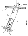
- the outside diameter of the sight tube 15 is slightly smaller than the inside diameter of the tubular member 14, such that an annular space 17 is defined between the sight tube 15 and tubular member 14, as best shown in Figure 4.
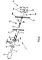
- the lower end of sight tube 15 extends through a hot gas duct member 18 and prevents excessive leakage of compressor discharge air into the turbine inlet section 19a. As best shown in Figure 2, it is preferred that the lower end of the sight tube be flush with the inside surface 18a of the duct member 18. Beyond the surface 18a is the turbine inlet section 19a, where the gas temperatures are extreme. In the practice of this invention, the reason for not allowing the sight tube 15 to extend into the hot gas duct is to lessen the chance that thermal degradation will cause the end of the tube to fragment and break off.
- the sight tube 15 has several small openings 20 which are located near the flange 14a of the tube, as shown in Figure 4.
- the compressor discharge section of the turbine compressor 21 is an area that lies between the casing 16 and the hot gas duct 18 (or ducts), as indicated generally by the numeral 21a.
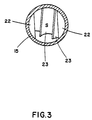
- Within the turbine section 19 there are several rows of stationary guide vanes 22, and several rows of rotating turbine blades 23.
- each row of turbine blades is mounted on a rotor shaft 24, and each row of the stationary guide vanes 22 is mounted within the turbine section, such that a row of guide vanes 22 is positioned before each row of the turbine blades 23.
- the pyrometer unit continuously monitors the temperature of the first row of rotating turbine blades 23 and utilizes this data to automatically control the firing temperature of the turbine.
- optical pyrometer systems There are several commercially available optical pyrometer systems that may be used in the practice of this invention. One of these systems, known as a two-color pyrometer, is preferred as the primary temperature monitoring system in this invention.
- the detector of this unit responds to two wavelength bands of radiation, in which the temperature data is calculated as a ratio product of the two wavelengths.
- a particular advantage of this unit is its ability to compensate for changes in emissivity from the rotating blades. Another advantage is that the unit can compensate for variations in the transmission of the radiation through the sight glass, which can be caused by films or other materials that might obscure the view through the glass. Since the detector has a slow speed of response, a profile of individual blade temperatures cannot be obtained, but it does have the capability of reading out average temperature values.
- Another commercially available optical system known as a spectrum analyzer, may be used in the practice of this invention to monitor the temperature of the rotating blades in a gas turbine.
- This unit can be used either in place of the pyrometer systems described above, or as a secondary instrument to supplement temperature data obtained by either of these instruments.
- a specific advantage of this unit is a detector that responds to radiant energy wavelengths across the entire spectrum, that is, from infrared to ultraviolet.
- the optical pyrometer unit 10 and the sight tube assembly are installed, as previously described, in a position such as that shown in Figures 1 and 2.
- the turbine is started and valve 12 is moved to its open position.
- the pyrometer unit 10 is then adjusted to give a direct and clear view of a selected target spot on the first row of the rotating turbine blades 23.
- a typical target spot is indicated schematically by a small "s" that appears on one of the turbine blades that is passing through the field of view.
- the line of sight As illustrated in the drawings, the line of sight, indicated by reference numeral 26, follows a direct path from the pyrometer unit 10, through valve 12, sight tube 15, and passes through the opening between two of the stationary guide vanes 22 in the first row of the vanes. As mentioned earlier, the first row of the stationary guide vanes 22 is positioned ahead of the first row of turbine blades 23.
- the function of the optical pyrometer unit 10 is to continuously monitor and sense the temperature of the turbine blades 23.
- the temperature data is transmitted to an electronic control circuit (not shown), which controls various turbine operating conditions, such as inlet gas temperature, outlet gas temperature, fuel input, and the like. This enables the control circuit to automatically regulate the fuel supply to the turbine, and thus maintain the firing temperature at a desired level.
- the sight glass 13 has the function of a viewing window for the pyrometer unit 10. Since the sight glass 13 is a solid piece of material with no openings therein, it functions as a critical pressure seal between the turbine and the pyrometer unit 10 when the valve 12 is in an open position.
- valve 12 provides a means for isolating the sight glass 13 and pyrometer unit 10 from the turbine engine environment. As pointed out earlier, this is an important feature of this invention, because it makes it possible to remove and replace the pyrometer unit 10 or the sight glass 13, or to service the instrument while the turbine is running.
- the scope of this invention also includes a second embodiment in which the valve 12 is omitted from the structure illustrated herein. In this embodiment the coupler neck 11 of the pyrometer unit 10 is connected directly to the flanges 14a and 15a of the tubular member 14 and sight tube 15, with the sight glass 13 being positioned between the flange of the coupler neck 11 and the flange 15a of the sight tube 15.
- the practice of this invention also includes being able to install the sight tube in a position that will allow the pyrometer unit, or another sensing instrument, to view other components internal to the engine, such as the stationary guide vanes, the hot gas duct, the combustors, or other parts.
- Another type of pyrometer that could be used in this invention is one that has been tuned to the emissions wavelengths of the gases present in the hot gas duct.
- a pyrometer could be used in conjunction with a sight tube, installed as described herein, and the sight tube could be purged with an appropriate gas that freely transmits the radiation emitted by the gases in the hot gas duct. This would enable the pyrometer to monitor the temperature of the gases in the hot gas duct.
- the disclosed invention has been illustrated in the drawings as a gas turbine utilizing a single hot-gas conduit.
- the invention is applicable to gas turbines which include a plurality of hot-gas conduits as indicated by the verbal description.
- the invention was first utilized in a multiple-conduit turbine.
- the number of hot-gas conduits is a matter of gas turbine design, and bears no relationship to the subject matter of the present invention.
Landscapes
- Physics & Mathematics (AREA)
- General Physics & Mathematics (AREA)
- Spectroscopy & Molecular Physics (AREA)
- Radiation Pyrometers (AREA)
- Turbine Rotor Nozzle Sealing (AREA)
- Chemical Vapour Deposition (AREA)
- Investigating Or Analysing Materials By Optical Means (AREA)
- Manufacture, Treatment Of Glass Fibers (AREA)
Abstract
Claims (4)
- Dispositif comprenant une turbine à gaz et un ensemble de tube de regard (A) servant à contrôler la température de chauffe de la turbine à gaz,
la turbine à gaz comprenant :a) une section de refoulement de compresseur (21a), située entre une enveloppe de turbine (16) et une paroi d'un élément de conduit de gaz chauds (18), etb) une section d'entrée de turbine (19a) comprenant au moins une rangée d'ailettes directrices fixes (22) et au moins une rangée d'ailettes mobiles de turbine (23) entraînées en rotation, la rangée d'ailettes directrices fixes (22) étant située entre la paroi de l'élément de conduit de gaz chauds (18) et la rangée d'ailettes mobiles de turbine (23) entraînées en rotation,
l'ensemble de tube de regard (A) comprenant :c) un pyromètre optique (10) etd) un tube de regard (15) qui a une première extrémité reliée au pyromètre optique (10) et qui est disposé dans la turbine à gaz de façon telle qu'une ligne de visée (26) s'étend du pyromètre optique (10) à la rangée d'ailettes mobiles de turbine (23) entraînées en rotation,
caractérisé en ce que :e) le pyromètre optique (10) est disposé à une certaine distance de l'enveloppe de turbine (16), à l'extérieur de la turbine à gaz,f) le tube de regard (15) comporte une seconde extrémité s'étendant dans la paroi de l'élément de conduit de gaz chauds (18), cette seconde extrémité du tube de regard (15) étant disposée en regard de ladite rangée d'ailettes fixes (22), et ce tube de regard est disposé à l'intérieur d'une pièce tubulaire (14) ayant une première extrémité fixée à l'enveloppe de turbine (16) et une seconde extrémité (14a) fixée au pyromètre optique (10), le diamètre extérieur du tube de regard (15) étant inférieur au diamètre intérieur de cette pièce tubulaire (14), de façon telle qu'un espace annulaire (17) soit défini entre le tube de regard (15) et la pièce tubulaire (14), etg) des moyens sont prévus pour ajuster la ligne de visée (26) de façon qu'elle puisse voir directement soit une zone choisie de deux ailettes directrices (22) adjacentes, soit une zone choisie des ailettes de turbine (23) entraînées en rotation. - Dispositif suivant la revendication 1, caractérisé en ce que l'espace annulaire (17) entourant le tube de regard (15) est agencé de façon à offrir aux fluides une communication avec la section de refoulement de compression (21a) de la turbine à gaz, plusieurs orifices (20) étant ménagés dans le tube de regard (15) en une position proche de la première extrémité de ce tube de regard (15), ces orifices (20) étant agencés de façon à offrir aux fluides une communication avec l'espace annulaire, de sorte que le tube de regard (15) est soumis à une purge à l'air comprimé à partir de la section de refoulement de compresseur (21a).
- Dispositif suivant l'une quelconque des revendications précédentes, caractérisé en ce que la ligne de visée (26) et l'arbre de turbine sur lequel les ailettes mobiles (23) sont montées font entre eux un angle à côtés non parallèles et ne se coupant pas qui est compris entre 20° et 80°.
- Dispositif suivant l'une quelconque des revendications précédentes, caractérisé en ce que le pyromètre optique (10) comprend un col d'accouplement (11), ayant une extrémité ouverte, une vanne (12), ayant une première et une seconde extrémités, la première extrémité étant reliée à l'extrémité ouverte du col d'accouplement (11), et un élément transparent (13) disposé entre le col d'accouplement (11) et la première extrémité de la vanne (12), la seconde extrémité (14a) du tube de visée (15) étant reliée à la seconde extrémité de cette vanne (12), de sorte que, lorsque la vanne est en position fermée, l'élément transparent (13) et le pyromètre optique (10) sont isolés du milieu interne de la section d'entrée de turbine (19a).
Applications Claiming Priority (4)
| Application Number | Priority Date | Filing Date | Title |
|---|---|---|---|
| US61865884A | 1984-06-08 | 1984-06-08 | |
| US618658 | 1984-06-08 | ||
| US730007 | 1985-05-02 | ||
| US06/730,007 US4648711A (en) | 1984-06-08 | 1985-05-02 | Sight tube assembly and sensing instrument for controlling a gas turbine |
Publications (3)
| Publication Number | Publication Date |
|---|---|
| EP0183846A1 EP0183846A1 (fr) | 1986-06-11 |
| EP0183846A4 EP0183846A4 (fr) | 1987-09-15 |
| EP0183846B1 true EP0183846B1 (fr) | 1993-04-14 |
Family
ID=27088292
Family Applications (1)
| Application Number | Title | Priority Date | Filing Date |
|---|---|---|---|
| EP85903897A Expired - Lifetime EP0183846B1 (fr) | 1984-06-08 | 1985-06-03 | Assemblage de tube de regard de pyrometre optique permettant la commande d'une turbine a gaz |
Country Status (14)
| Country | Link |
|---|---|
| US (1) | US4648711A (fr) |
| EP (1) | EP0183846B1 (fr) |
| JP (1) | JPH0663855B2 (fr) |
| KR (1) | KR900003564B1 (fr) |
| CN (1) | CN1006998B (fr) |
| AU (1) | AU564325B2 (fr) |
| BR (1) | BR8506776A (fr) |
| CA (1) | CA1248358A (fr) |
| DD (1) | DD239440A5 (fr) |
| DE (1) | DE3587265T2 (fr) |
| IN (2) | IN165102B (fr) |
| MY (1) | MY102697A (fr) |
| WO (1) | WO1986000131A1 (fr) |
| ZA (1) | ZA854344B (fr) |
Families Citing this family (31)
| Publication number | Priority date | Publication date | Assignee | Title |
|---|---|---|---|---|
| US5201227A (en) * | 1992-03-05 | 1993-04-13 | Ishikawajima-Harima Jukogyo Kabushiki Kaisha | Device for measuring vibrations on rotating blade |
| US5226731A (en) * | 1992-05-28 | 1993-07-13 | Electric Power Research Institute | Apparatus for measuring rotor exhaust gas bulk temperature in a combustion turbine and method therefor |
| CA2141592A1 (fr) * | 1992-08-10 | 1994-02-17 | Hilger A. Walter | Procede et dispositif pour la surveillance du niveau vibrationnel dans un compresseur axial |
| KR100296671B1 (ko) * | 1992-08-10 | 2001-10-24 | 스티븐에스. 그레이스 | 압축기의제어와모니터링을위한장치및공정 |
| AU4637393A (en) * | 1992-08-10 | 1994-03-03 | Dow Deutschland Inc. | Process for detecting fouling of an axial compressor |
| EP0654141B1 (fr) * | 1992-08-10 | 1999-07-07 | Dow Deutschland Inc. | Adaptateur pour monter un detecteur de pression sur un logement de turbine a gaz |
| US5316385A (en) * | 1993-03-30 | 1994-05-31 | The United States Of America As Represented By The Administrator Of The National Aeronautics And Space Administration | Correction-free pyrometry in radiant wall furnaces |
| US5421652A (en) * | 1993-12-21 | 1995-06-06 | General Electric Company | Pyrometer adapter |
| FR2718237B1 (fr) * | 1994-03-30 | 1996-06-21 | Europ Propulsion | Dispositif de mesure optique de température cryogénique. |
| US5867977A (en) * | 1996-05-14 | 1999-02-09 | The Dow Chemical Company | Method and apparatus for achieving power augmentation in gas turbines via wet compression |
| US5930990A (en) * | 1996-05-14 | 1999-08-03 | The Dow Chemical Company | Method and apparatus for achieving power augmentation in gas turbines via wet compression |
| US6733173B1 (en) * | 1996-12-19 | 2004-05-11 | Diamond Power International, Inc. | Pyrometer for measuring the temperature of a gas component within a furnace |
| DE19736276B4 (de) * | 1997-08-21 | 2006-07-27 | Alstom Technology Ltd | Optisches Pyrometer für Gasturbinen |
| US6250064B1 (en) | 1999-05-07 | 2001-06-26 | General Electric Co. | Gas turbine inlet air integrated water saturation and supersaturation system and related process |
| US6698920B1 (en) | 2000-05-08 | 2004-03-02 | General Electric Company | Temperature measuring system and optical switch used therein |
| US6579005B2 (en) * | 2000-12-28 | 2003-06-17 | General Electric Company | Utilization of pyrometer data to detect oxidation |
| ITMI20011948A1 (it) * | 2001-09-18 | 2003-03-18 | Nuovo Pignone Spa | Dispositivo anti-condensa per un sensore di fiamma di una camera di combustione |
| US6786635B2 (en) * | 2002-11-06 | 2004-09-07 | General Electric Company | Turbine blade (bucket) health monitoring and prognosis using neural network based diagnostic techniques in conjunction with pyrometer signals |
| US20040114666A1 (en) * | 2002-12-17 | 2004-06-17 | Hardwicke Canan Uslu | Temperature sensing structure, method of making the structure, gas turbine engine and method of controlling temperature |
| US20040179575A1 (en) * | 2003-01-23 | 2004-09-16 | Markham James R. | Instrument for temperature and condition monitoring of advanced turbine blades |
| DE102004049789A1 (de) * | 2004-10-12 | 2006-04-13 | BEGO Bremer Goldschlägerei Wilh. Herbst GmbH & Co. KG | Vorrichtung zur berührungslosen Messung der Temperatur in einem Schmelzofen |
| US7633066B2 (en) * | 2006-05-22 | 2009-12-15 | General Electric Company | Multiwavelength pyrometry systems |
| US8790006B2 (en) * | 2009-11-30 | 2014-07-29 | General Electric Company | Multiwavelength thermometer |
| CN101979840B (zh) * | 2010-10-21 | 2013-04-10 | 华中科技大学 | 高温高压环境下的视窗结构及其加工工艺 |
| US8158428B1 (en) * | 2010-12-30 | 2012-04-17 | General Electric Company | Methods, systems and apparatus for detecting material defects in combustors of combustion turbine engines |
| JP5951548B2 (ja) * | 2013-04-04 | 2016-07-13 | 三菱重工業株式会社 | プローブシステム、エンジン、検査方法及びプログラム |
| US9482579B2 (en) | 2013-09-03 | 2016-11-01 | General Electric Company | Systems and methods for planar temperature measurement |
| US10697317B2 (en) | 2016-03-17 | 2020-06-30 | General Electric Company | Optical imaging system for a gas turbine engine |
| US20170356342A1 (en) * | 2016-06-14 | 2017-12-14 | General Electric Company | Circuit-level heating for wide wobbe fuels in dln gas turbine combustion |
| CN113188798B (zh) * | 2021-04-25 | 2022-07-22 | 中国航发湖南动力机械研究所 | 一种用于航空发动机转子的超高温实验装置 |
| CN120427691A (zh) * | 2025-06-18 | 2025-08-05 | 内蒙古汇能煤化工有限公司 | 一种基于温度传感器的汽轮机叶片无损检测装置 |
Family Cites Families (6)
| Publication number | Priority date | Publication date | Assignee | Title |
|---|---|---|---|---|
| US2576514A (en) * | 1949-06-11 | 1951-11-27 | Cons Mining & Smelting Co | Pyrometer |
| GB694715A (en) * | 1949-06-22 | 1953-07-29 | Armstrong Siddeley Motors Ltd | Temperature measuring means |
| GB1092590A (en) * | 1966-08-04 | 1967-11-29 | Land Pyrometers Ltd | Improvements in or relating to air-purge units for radiation pyrometers |
| GB1589531A (en) * | 1978-02-07 | 1981-05-13 | Smiths Industries Ltd | Optical devices and engine installations including such devices |
| US4306835A (en) * | 1979-11-20 | 1981-12-22 | Avco Corporation | Air purging unit for an optical pyrometer of a gas turbine engine |
| US4411533A (en) * | 1981-04-27 | 1983-10-25 | Texaco Inc. | System for measuring temperature of hot gases laden with entrained solids |
-
1985
- 1985-05-02 US US06/730,007 patent/US4648711A/en not_active Expired - Fee Related
- 1985-06-03 AU AU46764/85A patent/AU564325B2/en not_active Ceased
- 1985-06-03 EP EP85903897A patent/EP0183846B1/fr not_active Expired - Lifetime
- 1985-06-03 KR KR1019860700074A patent/KR900003564B1/ko not_active Expired
- 1985-06-03 BR BR8506776A patent/BR8506776A/pt not_active IP Right Cessation
- 1985-06-03 WO PCT/US1985/001042 patent/WO1986000131A1/fr not_active Ceased
- 1985-06-03 DE DE8585903897T patent/DE3587265T2/de not_active Expired - Fee Related
- 1985-06-03 JP JP60503491A patent/JPH0663855B2/ja not_active Expired - Lifetime
- 1985-06-07 DD DD85277163A patent/DD239440A5/de not_active IP Right Cessation
- 1985-06-07 ZA ZA854344A patent/ZA854344B/xx unknown
- 1985-06-07 IN IN419/MAS/85A patent/IN165102B/en unknown
- 1985-06-07 CA CA000483410A patent/CA1248358A/fr not_active Expired
- 1985-07-06 CN CN85105166A patent/CN1006998B/zh not_active Expired
-
1987
- 1987-09-28 MY MYPI87002083A patent/MY102697A/en unknown
-
1989
- 1989-01-09 IN IN21/MAS/89A patent/IN168690B/en unknown
Also Published As
| Publication number | Publication date |
|---|---|
| CA1248358A (fr) | 1989-01-10 |
| WO1986000131A1 (fr) | 1986-01-03 |
| IN165102B (fr) | 1989-08-19 |
| CN85105166A (zh) | 1986-12-03 |
| CN1006998B (zh) | 1990-02-28 |
| ZA854344B (en) | 1987-02-25 |
| DE3587265T2 (de) | 1993-07-29 |
| JPS61500812A (ja) | 1986-04-24 |
| AU564325B2 (en) | 1987-08-06 |
| JPH0663855B2 (ja) | 1994-08-22 |
| EP0183846A4 (fr) | 1987-09-15 |
| KR860700149A (ko) | 1986-03-31 |
| US4648711A (en) | 1987-03-10 |
| IN168690B (fr) | 1991-05-18 |
| AU4676485A (en) | 1986-01-10 |
| MY102697A (en) | 1992-09-30 |
| KR900003564B1 (ko) | 1990-05-21 |
| DE3587265D1 (de) | 1993-05-19 |
| EP0183846A1 (fr) | 1986-06-11 |
| DD239440A5 (de) | 1986-09-24 |
| BR8506776A (pt) | 1986-11-25 |
Similar Documents
| Publication | Publication Date | Title |
|---|---|---|
| US4648711A (en) | Sight tube assembly and sensing instrument for controlling a gas turbine | |
| US5257496A (en) | Combustion control for producing low NOx emissions through use of flame spectroscopy | |
| EP0039706B1 (fr) | Dispositif de purge d'air pour un pyrometre optique d'un moteur de turbine a gaz | |
| US5487266A (en) | Combustion control for producing low NOx emissions through use of flame spectroscopy | |
| US6062811A (en) | On-line monitor for detecting excessive temperatures of critical components of a turbine | |
| US5148667A (en) | Gas turbine flame diagnostic monitor | |
| EP0236336B1 (fr) | Systeme de regulation de refroidissement changeable pour un anneau de renforcement de turbines et un rotor | |
| US5226731A (en) | Apparatus for measuring rotor exhaust gas bulk temperature in a combustion turbine and method therefor | |
| EP4060308B1 (fr) | Système et procédé de détection de fuite | |
| US8650883B2 (en) | System and method for operating a gas turbine | |
| US20140376588A1 (en) | System and method for on-line optical monitoring and control of a gas turbine engine | |
| GB2104966A (en) | Closed loop control for tip clearance of a gas turbine engine | |
| US8033719B2 (en) | Gas turbine with protective sheath for a probe and method for protecting an instrument lead which is laid in a protective sheath | |
| Huitenga et al. | Development approach to the dry low emission combustion system of MAN diesel and turbo gas turbines | |
| EP4442966A1 (fr) | Système de mesure de température de moteur à turbine à gaz | |
| HK1027031A (en) | Topical drug preparations | |
| JPH01176922A (ja) | ガスタービンの排気温度検出装置 | |
| Kirby et al. | Infrared Thermometry for Control and Monitoring of Industrial Gas Turbines | |
| EP3660293A1 (fr) | Procédé de surveillance de la fonction de soupapes de dérivation dans une turbine à gaz et installation de turbine à gaz | |
| RU1841077C (ru) | Объектив оптического пирометрического преобразователя и способ защиты его от копоти и перегрева | |
| CN112361374A (zh) | 一种燃气轮机燃烧室火焰检测装置 | |
| Morey et al. | Diagnostics from imaging inside gas turbine combustors | |
| Kroniger et al. | Borescope for Infrared Thermography of Turbine Guide Vanes During Operation | |
| Beynon | Infra-red radiation thermometry applied to the development and control of gas turbines | |
| Quentin et al. | Modified Fuel Control for a Large Heavy-Duty Combustion Turbine-Generator |
Legal Events
| Date | Code | Title | Description |
|---|---|---|---|
| PUAI | Public reference made under article 153(3) epc to a published international application that has entered the european phase |
Free format text: ORIGINAL CODE: 0009012 |
|
| 17P | Request for examination filed |
Effective date: 19860227 |
|
| AK | Designated contracting states |
Kind code of ref document: A1 Designated state(s): BE CH DE FR GB IT LI NL SE |
|
| A4 | Supplementary search report drawn up and despatched |
Effective date: 19870915 |
|
| 17Q | First examination report despatched |
Effective date: 19900523 |
|
| GRAA | (expected) grant |
Free format text: ORIGINAL CODE: 0009210 |
|
| AK | Designated contracting states |
Kind code of ref document: B1 Designated state(s): BE CH DE FR GB IT LI NL SE |
|
| REF | Corresponds to: |
Ref document number: 3587265 Country of ref document: DE Date of ref document: 19930519 |
|
| ET | Fr: translation filed | ||
| ITF | It: translation for a ep patent filed | ||
| PLBE | No opposition filed within time limit |
Free format text: ORIGINAL CODE: 0009261 |
|
| STAA | Information on the status of an ep patent application or granted ep patent |
Free format text: STATUS: NO OPPOSITION FILED WITHIN TIME LIMIT |
|
| 26N | No opposition filed | ||
| EAL | Se: european patent in force in sweden |
Ref document number: 85903897.8 |
|
| PGFP | Annual fee paid to national office [announced via postgrant information from national office to epo] |
Ref country code: FR Payment date: 19950212 Year of fee payment: 11 |
|
| PGFP | Annual fee paid to national office [announced via postgrant information from national office to epo] |
Ref country code: SE Payment date: 19950217 Year of fee payment: 11 Ref country code: DE Payment date: 19950217 Year of fee payment: 11 |
|
| PGFP | Annual fee paid to national office [announced via postgrant information from national office to epo] |
Ref country code: CH Payment date: 19950220 Year of fee payment: 11 |
|
| PGFP | Annual fee paid to national office [announced via postgrant information from national office to epo] |
Ref country code: BE Payment date: 19950306 Year of fee payment: 11 |
|
| PG25 | Lapsed in a contracting state [announced via postgrant information from national office to epo] |
Ref country code: SE Effective date: 19960604 |
|
| PG25 | Lapsed in a contracting state [announced via postgrant information from national office to epo] |
Ref country code: LI Effective date: 19960630 Ref country code: CH Effective date: 19960630 Ref country code: BE Effective date: 19960630 |
|
| PGFP | Annual fee paid to national office [announced via postgrant information from national office to epo] |
Ref country code: NL Payment date: 19960831 Year of fee payment: 12 |
|
| PGFP | Annual fee paid to national office [announced via postgrant information from national office to epo] |
Ref country code: GB Payment date: 19961129 Year of fee payment: 12 |
|
| BERE | Be: lapsed |
Owner name: THE DOW CHEMICAL CY Effective date: 19960630 |
|
| REG | Reference to a national code |
Ref country code: CH Ref legal event code: PL |
|
| PG25 | Lapsed in a contracting state [announced via postgrant information from national office to epo] |
Ref country code: FR Effective date: 19970228 |
|
| PG25 | Lapsed in a contracting state [announced via postgrant information from national office to epo] |
Ref country code: DE Effective date: 19970301 |
|
| EUG | Se: european patent has lapsed |
Ref document number: 85903897.8 |
|
| REG | Reference to a national code |
Ref country code: FR Ref legal event code: ST |
|
| PG25 | Lapsed in a contracting state [announced via postgrant information from national office to epo] |
Ref country code: GB Effective date: 19970603 |
|
| PG25 | Lapsed in a contracting state [announced via postgrant information from national office to epo] |
Ref country code: NL Effective date: 19980101 |
|
| GBPC | Gb: european patent ceased through non-payment of renewal fee |
Effective date: 19970603 |
|
| NLV4 | Nl: lapsed or anulled due to non-payment of the annual fee |
Effective date: 19980101 |