EP0183879A1 - Système de régulation électronique du débit d'un fluide - Google Patents
Système de régulation électronique du débit d'un fluide Download PDFInfo
- Publication number
- EP0183879A1 EP0183879A1 EP84308446A EP84308446A EP0183879A1 EP 0183879 A1 EP0183879 A1 EP 0183879A1 EP 84308446 A EP84308446 A EP 84308446A EP 84308446 A EP84308446 A EP 84308446A EP 0183879 A1 EP0183879 A1 EP 0183879A1
- Authority
- EP
- European Patent Office
- Prior art keywords
- fuel
- fluid
- common
- flow
- lines
- Prior art date
- Legal status (The legal status is an assumption and is not a legal conclusion. Google has not performed a legal analysis and makes no representation as to the accuracy of the status listed.)
- Withdrawn
Links
- 239000012530 fluid Substances 0.000 title claims abstract description 70
- 230000001105 regulatory effect Effects 0.000 title claims 4
- 239000000446 fuel Substances 0.000 claims abstract description 76
- 238000002485 combustion reaction Methods 0.000 claims abstract description 32
- 230000004044 response Effects 0.000 claims description 6
- 238000000034 method Methods 0.000 claims 5
- 230000001276 controlling effect Effects 0.000 claims 3
- 239000007789 gas Substances 0.000 description 27
- VNWKTOKETHGBQD-UHFFFAOYSA-N methane Chemical compound C VNWKTOKETHGBQD-UHFFFAOYSA-N 0.000 description 16
- 239000000203 mixture Substances 0.000 description 10
- ATUOYWHBWRKTHZ-UHFFFAOYSA-N Propane Chemical compound CCC ATUOYWHBWRKTHZ-UHFFFAOYSA-N 0.000 description 8
- 238000013461 design Methods 0.000 description 6
- 239000003502 gasoline Substances 0.000 description 4
- 239000001294 propane Substances 0.000 description 4
- 238000010586 diagram Methods 0.000 description 3
- 239000003607 modifier Substances 0.000 description 3
- 239000003345 natural gas Substances 0.000 description 3
- 230000001133 acceleration Effects 0.000 description 2
- 238000013459 approach Methods 0.000 description 2
- 230000008901 benefit Effects 0.000 description 2
- 230000008859 change Effects 0.000 description 2
- 238000012937 correction Methods 0.000 description 2
- 230000001419 dependent effect Effects 0.000 description 2
- 238000004880 explosion Methods 0.000 description 2
- 230000003321 amplification Effects 0.000 description 1
- QVGXLLKOCUKJST-UHFFFAOYSA-N atomic oxygen Chemical compound [O] QVGXLLKOCUKJST-UHFFFAOYSA-N 0.000 description 1
- 238000006243 chemical reaction Methods 0.000 description 1
- 239000003245 coal Substances 0.000 description 1
- 239000002131 composite material Substances 0.000 description 1
- 238000006073 displacement reaction Methods 0.000 description 1
- 238000005516 engineering process Methods 0.000 description 1
- 239000002737 fuel gas Substances 0.000 description 1
- 230000008676 import Effects 0.000 description 1
- 239000007788 liquid Substances 0.000 description 1
- 230000001473 noxious effect Effects 0.000 description 1
- 238000003199 nucleic acid amplification method Methods 0.000 description 1
- 239000001301 oxygen Substances 0.000 description 1
- 229910052760 oxygen Inorganic materials 0.000 description 1
- 238000004886 process control Methods 0.000 description 1
- 238000012545 processing Methods 0.000 description 1
- 230000002250 progressing effect Effects 0.000 description 1
- 230000002459 sustained effect Effects 0.000 description 1
- 239000002699 waste material Substances 0.000 description 1
- 238000003466 welding Methods 0.000 description 1
Images

Classifications
-
- F—MECHANICAL ENGINEERING; LIGHTING; HEATING; WEAPONS; BLASTING
- F02—COMBUSTION ENGINES; HOT-GAS OR COMBUSTION-PRODUCT ENGINE PLANTS
- F02M—SUPPLYING COMBUSTION ENGINES IN GENERAL WITH COMBUSTIBLE MIXTURES OR CONSTITUENTS THEREOF
- F02M21/00—Apparatus for supplying engines with non-liquid fuels, e.g. gaseous fuels stored in liquid form
- F02M21/02—Apparatus for supplying engines with non-liquid fuels, e.g. gaseous fuels stored in liquid form for gaseous fuels
- F02M21/0218—Details on the gaseous fuel supply system, e.g. tanks, valves, pipes, pumps, rails, injectors or mixers
- F02M21/023—Valves; Pressure or flow regulators in the fuel supply or return system
- F02M21/0239—Pressure or flow regulators therefor
-
- F—MECHANICAL ENGINEERING; LIGHTING; HEATING; WEAPONS; BLASTING
- F02—COMBUSTION ENGINES; HOT-GAS OR COMBUSTION-PRODUCT ENGINE PLANTS
- F02D—CONTROLLING COMBUSTION ENGINES
- F02D19/00—Controlling engines characterised by their use of non-liquid fuels, pluralities of fuels, or non-fuel substances added to the combustible mixtures
- F02D19/02—Controlling engines characterised by their use of non-liquid fuels, pluralities of fuels, or non-fuel substances added to the combustible mixtures peculiar to engines working with gaseous fuels
- F02D19/021—Control of components of the fuel supply system
- F02D19/023—Control of components of the fuel supply system to adjust the fuel mass or volume flow
-
- F—MECHANICAL ENGINEERING; LIGHTING; HEATING; WEAPONS; BLASTING
- F02—COMBUSTION ENGINES; HOT-GAS OR COMBUSTION-PRODUCT ENGINE PLANTS
- F02D—CONTROLLING COMBUSTION ENGINES
- F02D35/00—Controlling engines, dependent on conditions exterior or interior to engines, not otherwise provided for
- F02D35/0015—Controlling engines, dependent on conditions exterior or interior to engines, not otherwise provided for using exhaust gas sensors
- F02D35/0046—Controlling fuel supply
- F02D35/0053—Controlling fuel supply by means of a carburettor
- F02D35/0069—Controlling the fuel flow only
-
- Y—GENERAL TAGGING OF NEW TECHNOLOGICAL DEVELOPMENTS; GENERAL TAGGING OF CROSS-SECTIONAL TECHNOLOGIES SPANNING OVER SEVERAL SECTIONS OF THE IPC; TECHNICAL SUBJECTS COVERED BY FORMER USPC CROSS-REFERENCE ART COLLECTIONS [XRACs] AND DIGESTS
- Y02—TECHNOLOGIES OR APPLICATIONS FOR MITIGATION OR ADAPTATION AGAINST CLIMATE CHANGE
- Y02T—CLIMATE CHANGE MITIGATION TECHNOLOGIES RELATED TO TRANSPORTATION
- Y02T10/00—Road transport of goods or passengers
- Y02T10/10—Internal combustion engine [ICE] based vehicles
- Y02T10/30—Use of alternative fuels, e.g. biofuels
Definitions
- This invention relates to precision control of a flow of fluid in fluid conducting lines, and applies particularly, though not exclusively, to the control of gaseous fuel to an internal combustion engine. Still more specifically, the invention relates to the control of fuel supply to internal combustion engines by means of electronic digital controls.
- gaseous fuels such as natural gas (methane) and propane which show great promise as an alternative to gasoline as a power source for motor vehicles. It has been recognized that the increased use of gaseous fuels for internal combustion engines would reduce the amount of oil which must be imported into countries such as Canada and the United States. There is at present a sufficient supply of gaseous methane and propane to permit such expanded use.
- the principal source of methane is now natural gas. However, it can be produced from coal and waste biological products which are renewable. Methane and propane are also attractive because they produce less polluting exhaust products.
- the present invention proposes a new concept that will replace the venturi-diaphragm system with a regulator capable of directly converting electronic digital signals into a gas flow directly and accurately proportional to these digits.
- the invention permits a high degree of system sophistication to be achieved at very low cost.
- fuel flow can be controlled within very narrow limits in response to digital signals from an electronic processor.
- the key element in the proposal is an electromechnical device (EDGAR * ) capable of accepting the electronic digital input, and providing a fuel flow which is adjustable in small discrete steps.
- EDGAR electromechnical device
- apparatus for controlling the rate of flow of compressible fluid from a source to a destination including a plurality of fluid conducting lines, the relative flow rates through said fluid conducting lines being proportional to preselected values (preferably values proportional to successive powers of two for reasons which will become apparent) when the pressure differential across said lines is sufficient to create choked flow conditions therein.
- the apparatus includes means to connect said plurality of fluid conducting lines in parallel between said source and said destination.
- a control valve is located in each of said fluid conducting lines, each said control valve being operable to fully open and fully closed positions.
- An electronic control means controls selectively the opening and closing of each of said valves.
- One preferred form of the invention provides an electronically controlled fuel system for an internal combustion engine.
- This system typically includes a plurality of fluid conducting lines connected in parallel and having relative fluid carrying capacities proportional to powers of two when operating under choked flow conditions.
- a solenoid control valve is located in each of the fluid conducting lines, each of said solenoid control valves being operable to fully open and fully closed positions.
- An electronic processor is arranged to control selectively the opening and closing of each of said valves by means of digital signals applied to the solenoids.
- a sensor means to generate electrical signals indicative of the operating parameters of said internal combustion engine is provided, said electrical signals being applied to the electronic processor.
- An air/fuel mixer having an input to which the combined output of said plurality of fluid conducting lines is connected is also provided and its output is connected to said internal combustion engine.
- Said electronic processor automatically adjusts the combined fluid flow from said plurality of fluid conducting lines in a series of discrete steps by opening and closing said control valves in response to the fuel requirements of said internal combustion engine as indicated by the electrical signals generated by the sensor means.
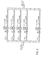
- the key element of the fuel regulation system illustrated in the block diagram of Figure 1 is the electronic digital to analog gas regulator 1.
- This is an electromechanical device designed to be operated by digital electronic signals from an electronic processor so as to produce an analog gas output adjustable in many discrete steps by means of the digital signals.
- the electronic processor 2 manipulates the data from a plurality of sensors 3a to 3n, and converts this data into binary digital signals, which acccurately represent the fuel requirements of the engine at a particular time, and which are applied to the electronic digital to analog regulator in a manner which will be more fully described hereinafter.
- the electronic processor 2 can be of any suitable design.
- the data from the sensors 3a to 3n is manipulated by analog electrical circuitry with the results being converted to digital form simply as an interface to the electomechanical flow arrangement to be described hereafter.
- the data from the sensors can be converted to digital form at the outset and manipulated by a programmable digital processor, e.g.
- processor 2 regardless of its exact design, produces a digital output, i.e. a binary output, representing the desired fluid flow.
- Sensors 3a, 3b, 3c, ... 3n detect the various parameters which affect engine performance such as: engine temperature, engine r.p.m., throttle position, intake air mass flow, and composition of exhaust gases. Each sensor produces an electrical signal indicative of the value of the parameter it measures, and the signals produced by the various sensors are applied to inputs of the electronic digital processor 2.
- Fuel usually methane or propane, is stored in fuel storage tank 4 at a pressure which may be 3000 psi or more depending on economic and safety considerations. Pressure is reduced in high pressure regulator 5 to approximately 100 psi for application to the electronic digital to analog regulator. The metered fuel from the electronic digital to analog regulator is applied to the air stream in the air/fuel mixer 6 from whence the mixed air and fuel are fed to the intake of the internal combustion engine 7.
- the electronic digital to analog regulator shown in Figure 2 will now be described. It is seen to consist of a plurality of fluid conducting lines L0, Ll, L2 ... Ln connected in parallel between a common input or source Pl and a common output or user P2. In each of the fluid conducting lines there is a solenoid valve controlled by signals from the electronic digital processor to either fully on or fully off position. Also included in each line is a metering orifice, the dimensions of which determine the fluid carrying capacity of the particular line at the selected inlet pressure.
- Fluid mechanics dictates that if there is a large enough pressure differential between the gas at inlet port Pl and the gas at output port P2 then the flow in the orifice throat will be at sonic velocity, such flow being known as critical or choked flow. Under this flow condition a further decrease in pressure at output port P2 cannot affect the pressure in the orifice throat or the mass flow rate. So long as critical or choked flow conditions are maintained the mass of gas passing through each line per unit time will be directly proportional to the pressure at inlet port Pl. This phenomena is, per se, well known, reference being had to "Fluid Mechanics With Engineering Applications", Robert L. Daugherty et al, 7th Edition, McGraw-Hill Book Company, pages 259-261 and equation 9.25.
- the pressure differential between inlet port Pl and output port P2 is always such that each of the orifices operates in the chocked or critical flow condition when fluid is flowing therethrough. That is, the inlet-outlet pressure differential is always maintained at or above the critical value.
- the inlet pressure at port Pl is held constant.
- An inlet pressure of 100 psig is a typical input pressure when the present system is used to supply a large (454 c.i.d.) engine.
- the same basic system can thus be used, with no orifice size change, to supply smaller engines by simply reducing the inlet pressure in port Pl by an appropriate amount so long as choked or critical flow conditions are maintained in the orifices.
- the resulting saving in inventory by having one calibrated system for use with a wide variety of sizes of engines, or other users, provides a substantial cost advantage.
- Metering orifices MO, Ml, M2, M3, ... Mn regulate the gas flows Q0, Ql, Q2, Q3, ... Qn such that the gas flow from each line contributes a different amount to the total gas ouput.
- the contribution of each metering orifice M, contributing a gas flow Q is weighted according to its position in the binary number series.
- the values of the gas flows Q0, Ql, Q2, Q3, ... Qn in the fuel conducting lines L0, Ll, L2, L3, ... Ln obey the following mathematical relationship:
- Rate of flow in any one of the fluid conducting lines L0, Ll, L2, L3, ... Ln, when the associated solenoid valve is open, is dependent on the dimensions of the orifices of metering orifices M0, Ml, M2, M3, ... Mn.
- the orifices operate, as noted above, in a choked flow condition so that the rate of flow of fluid through each orifice is constant at constant inlet pressure.
- the number of increments of gas flow provided by "n" number of fluid conducting lines in the binary weighted system is 2 n - 1. The following listing shows the number of such increments for various numbers of lines.
- the resolution of such a system is a percentage which one of the incremental steps, which is equal to Q0, is of the maximum gas flow 00 + 01 + Q2 + Q3 + ... Qn.
- the resolution R is given by the equation
- n For values of n of 5, 6, 7 and 8 the resolutions are 3.23%, 1.59%, 0.79% and 0.39%. The above values of n are expected to cover the majority of practical applications.
- a system requires a maximum flow rate of 31.0 standard cubic feet perminute (scfm) at a resolution of 4.0%.
- the number of increments available with 5 bits is 31 so the least significant bit Q 0 is chosen as 1 scfm.
- Binary weighting determines the values of Q 1 , Q 2 , Q 3 , and Q 4 .
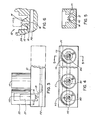
- the several solenoid control valves V0, Vl, ... Vn are connected to and along an elongated manifold 10, the latter having recesses 12 therein to receive the solenoids of the several control valves.
- the manifold 10 is also drilled in the lengthwise direction to provide a pair of spaced elongated ports, i.e. inlet port Pl and output port P2, both of which are common to the several solenoid control valves V.
- valve seat 14 includes a flow passage 16 communicating with outlet port P2 via metering orifice M, dimensioned in the manner described above.
- Each recess 12 also provides an annular region 18 surrounding valve seat 14, which region communicates with inlet port Pl via a short drilled passage 15. Passages 15 and 16 in this embodiment together with region 18 provide the flow lines L0, Ll, ... Ln described previously, each such flow line L having a respective metering orifice M therein.
- Each solenoid control valve V0, Vl, ... Vn includes a solenoid coil 20 and an associated plunger 22.
- the end of the plunger 22 is provided with a valve disc 24 which mates with valve seat 14 to provide a good seal when the plunger 22 moves to the valve closed position.
- inlet port Pl communicates with output port P2 via flow line L including annular region 18, flow passage 15 and 16 and metering orifice M.
- valve-manifold arrangement described above is very compact and well suited for many applications, especially in cases where the system is applied to internal combustion engines.
- the manner of operation of this arrangement will readily be apparent having regard to the foregoing description.
- Various types of quick-acting solenoid valves are commercially available such as Honeywell/Skinner V5 series valves (12 volt). These valves are provided with a flow metering option (RM), which option is not significant in the present case as each orifice is individually sized and drilled to provide the flow rate capacities referred to above.
- RM flow metering option
- valve life is important consideration.
- Commercially available valves are specifically as being capable of 20,000,000 operations at 10 cycles per second which would lead to a minimum life expectancy of 555 hours. At 60 miles per hour this would provide a minimum of 33,300 miles before expected valve failure.
- valve life would be much better than the calculated minimum, some of the reasons for this being:
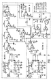
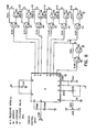
- Figs. 7 and 8 are complete schematics of the electronic processor. Fig. 7 is divided into blocks to which the following description pertains.
- Circuit block C provides a signal that is in direct proportion to air flow into the engine intake thus establishing an adjustable reference to which other modifiers can be added.
- Circuit block A provides a signal that reflects engine load and acts as a modifier to that produced by block C.
- Block D provides a modifier when the engine is operated within a set range of RPM indicative of idle, while block B sums the signals from blocks A, C and D to produce a composite signal that is applied to the analog to digital converter detailed in Figure 8.
- IC1 and IC8 are National LM2917 frequency to voltage converters.
- IC1 converts ignition pulses to an anolog voltage proportional to revolution per minute (RPM), a typical value being 0 to +5 volts output (pin 5, 10) for an input range of 0 to 5000 RPM.
- IC2 inverts and amplifies the output of IC1 producing a voltage of 0 volts at O RPM progressing to -10 volts at 5000 RPM.
- IC8 converts pulses from an air flow meter (Chrysler part #4267128) to an 0 to +5 volt analog signal proportional to the wide open throttle (WOT) air demand over the RPM range.
- WOT wide open throttle
- IC9 inverts and amplifies the output of IC8 producing at its output (pin 6) a voltage that "tracks" the output of IC2 under WOT conditions.
- the output of IC9 is equal to the output of IC2 only under WOT conditions. For a given RPM a throttle setting less than WOT will produce a proportionally smaller voltage at the output of IC9 and the difference between the IC2 and IC9 output voltage appears at the output of IC3 as of positive going correction signal that accurately reflects engine load.
- IC6 produces a negative going correction signal in the following way.
- the output of IC9 is applied to a voltage divider comprised of Re and Rf.
- the setting of Re determines the portion of the total voltage that is applied to the inverting input of IC6.
- the non-inverting input of IC6 is connected via a voltage divider to the output of IC9. This configuration of IC6 enables IC6 to amplify only the voltage appearing between the output of IC9 and the wiper of Re.
- IC6 output is negative going and is summed at the input of IC4 with the positive going signal from IC3.
- the position of the wiper determines the portion of the voltage produced by IC9 that appears between the wiper and ground as does the same wiper determine the portion of the voltage produced by IC9 that is applied to IC6.
- the sum of the voltage applied to IC6 and IC7 must equal the output of IC9.
- IC7 is simply a summing amplifier algebraically adding the outputs of IC5, Re and Rg.
- Re provides a voltage that is directly proportional to air flow and is the signal that meters fuel under "maximum economy" conditions.
- IC5 provides a modifying signal that adds to the signal provided by Re to increase the amount of fuel delivered when the engine is expected to produce maximum power.
- Rg simply provides a voltage that is used to add the required amount of fuel to compensate for engine variables under idle conditions.
- IC10A and IC10B form a "window" comparator by which the RPM range of the idle compensation circuit may be set.
- the output of IC7 drives an analog to Digital Converter (ADC) (e.g. a Teledyne 8700CJ) which converts the positive going analog signal into a digital binary format.
- ADC analog to Digital Converter
- Two stages of transistor amplification for each bit of the ADC are provided by transistors O a s Q b in order to achieve sufficient current gain to drive the valves of V0, Vl, V2---Vn of EDGAR the solenoid coils K only of which are represented in Fig. 8.
Landscapes
- Engineering & Computer Science (AREA)
- Chemical & Material Sciences (AREA)
- Combustion & Propulsion (AREA)
- Mechanical Engineering (AREA)
- General Engineering & Computer Science (AREA)
- Chemical Kinetics & Catalysis (AREA)
- General Chemical & Material Sciences (AREA)
- Oil, Petroleum & Natural Gas (AREA)
- Flow Control (AREA)
Priority Applications (1)
| Application Number | Priority Date | Filing Date | Title |
|---|---|---|---|
| EP84308446A EP0183879A1 (fr) | 1984-12-05 | 1984-12-05 | Système de régulation électronique du débit d'un fluide |
Applications Claiming Priority (1)
| Application Number | Priority Date | Filing Date | Title |
|---|---|---|---|
| EP84308446A EP0183879A1 (fr) | 1984-12-05 | 1984-12-05 | Système de régulation électronique du débit d'un fluide |
Publications (1)
| Publication Number | Publication Date |
|---|---|
| EP0183879A1 true EP0183879A1 (fr) | 1986-06-11 |
Family
ID=8192830
Family Applications (1)
| Application Number | Title | Priority Date | Filing Date |
|---|---|---|---|
| EP84308446A Withdrawn EP0183879A1 (fr) | 1984-12-05 | 1984-12-05 | Système de régulation électronique du débit d'un fluide |
Country Status (1)
| Country | Link |
|---|---|
| EP (1) | EP0183879A1 (fr) |
Cited By (8)
| Publication number | Priority date | Publication date | Assignee | Title |
|---|---|---|---|---|
| EP0420599A3 (en) * | 1989-09-29 | 1991-09-11 | Canadian Gas Association | Flow control system |
| WO1998007081A1 (fr) * | 1996-08-15 | 1998-02-19 | Honeywell B.V. | Systeme de commande de debit |
| EP0870916A3 (fr) * | 1997-04-08 | 1999-05-26 | MTM - Meccanica Tecnica Moderna S.r.l. | Unité et méthode d'injection pour alimenter en carburant gazeux un moteur à propulsion |
| US20100132692A1 (en) * | 2008-12-01 | 2010-06-03 | Timothy Scott Shaffer | Gas grill |
| EP1779084A4 (fr) * | 2004-07-21 | 2012-03-28 | Sensors Inc | Systeme de controle de flux diluant a fonctionnement rapide et procede d'echantillonnage d'analyse d'evacuation |
| US8978632B2 (en) | 2011-09-28 | 2015-03-17 | Hoerbiger Kompressortechnik Holding Gmbh | Ion sensing method for capacitive discharge ignition |
| US9464588B2 (en) | 2013-08-15 | 2016-10-11 | Kohler Co. | Systems and methods for electronically controlling fuel-to-air ratio for an internal combustion engine |
| US10054081B2 (en) | 2014-10-17 | 2018-08-21 | Kohler Co. | Automatic starting system |
Citations (4)
| Publication number | Priority date | Publication date | Assignee | Title |
|---|---|---|---|---|
| FR2304784A1 (fr) * | 1975-03-18 | 1976-10-15 | Nissan Motor | Systeme, en boucle fermee, de reglage du rapport de melange d'air et de combustible pour moteur a combustion interne |
| FR2380426A1 (fr) * | 1977-02-11 | 1978-09-08 | Acf Ind Inc | Appareillage de dosage d'air du carburateur d'un moteur a combustion interne |
| EP0075178A2 (fr) * | 1981-09-24 | 1983-03-30 | Trw Inc. | Méthode et appareil de commande de la vitesse d'un véhicule ou d'un moteur à combustion interne à injection |
| EP0110699A1 (fr) * | 1982-12-01 | 1984-06-13 | Solex (U.K.) Limited - In Liquidation | Système d'induction de mélange dans un moteur à combustion interne, à plusieurs cylindres |
-
1984
- 1984-12-05 EP EP84308446A patent/EP0183879A1/fr not_active Withdrawn
Patent Citations (4)
| Publication number | Priority date | Publication date | Assignee | Title |
|---|---|---|---|---|
| FR2304784A1 (fr) * | 1975-03-18 | 1976-10-15 | Nissan Motor | Systeme, en boucle fermee, de reglage du rapport de melange d'air et de combustible pour moteur a combustion interne |
| FR2380426A1 (fr) * | 1977-02-11 | 1978-09-08 | Acf Ind Inc | Appareillage de dosage d'air du carburateur d'un moteur a combustion interne |
| EP0075178A2 (fr) * | 1981-09-24 | 1983-03-30 | Trw Inc. | Méthode et appareil de commande de la vitesse d'un véhicule ou d'un moteur à combustion interne à injection |
| EP0110699A1 (fr) * | 1982-12-01 | 1984-06-13 | Solex (U.K.) Limited - In Liquidation | Système d'induction de mélange dans un moteur à combustion interne, à plusieurs cylindres |
Cited By (12)
| Publication number | Priority date | Publication date | Assignee | Title |
|---|---|---|---|---|
| EP0420599A3 (en) * | 1989-09-29 | 1991-09-11 | Canadian Gas Association | Flow control system |
| AU630510B2 (en) * | 1989-09-29 | 1992-10-29 | Ortech Corporation | Flow control system |
| WO1998007081A1 (fr) * | 1996-08-15 | 1998-02-19 | Honeywell B.V. | Systeme de commande de debit |
| EP0870916A3 (fr) * | 1997-04-08 | 1999-05-26 | MTM - Meccanica Tecnica Moderna S.r.l. | Unité et méthode d'injection pour alimenter en carburant gazeux un moteur à propulsion |
| EP1779084A4 (fr) * | 2004-07-21 | 2012-03-28 | Sensors Inc | Systeme de controle de flux diluant a fonctionnement rapide et procede d'echantillonnage d'analyse d'evacuation |
| US20100132692A1 (en) * | 2008-12-01 | 2010-06-03 | Timothy Scott Shaffer | Gas grill |
| US8863734B2 (en) * | 2008-12-01 | 2014-10-21 | General Electric Company | Gas grill |
| US8978632B2 (en) | 2011-09-28 | 2015-03-17 | Hoerbiger Kompressortechnik Holding Gmbh | Ion sensing method for capacitive discharge ignition |
| US9464588B2 (en) | 2013-08-15 | 2016-10-11 | Kohler Co. | Systems and methods for electronically controlling fuel-to-air ratio for an internal combustion engine |
| US10240543B2 (en) | 2013-08-15 | 2019-03-26 | Kohler Co. | Integrated ignition and electronic auto-choke module for an internal combustion engine |
| US10794313B2 (en) | 2013-08-15 | 2020-10-06 | Kohler Co. | Integrated ignition and electronic auto-choke module for an internal combustion engine |
| US10054081B2 (en) | 2014-10-17 | 2018-08-21 | Kohler Co. | Automatic starting system |
Similar Documents
| Publication | Publication Date | Title |
|---|---|---|
| US4487187A (en) | Electronically controlled fluid floro regulating system | |
| EP0420599B1 (fr) | Système de commande d'écoulement | |
| CA1185343A (fr) | Injection de carburant a commande electronique pour moteurs a combustion interne avec allumage par bougies | |
| US4838295A (en) | System for controlling mass flow rates of two gases | |
| US4641625A (en) | Fuel control system | |
| KR880001684B1 (ko) | 자동차용 내연기관의 공연비(空燃比) 제어방법 | |
| CN100370124C (zh) | 发动机燃料供给管理系统 | |
| US6978774B2 (en) | Emission control valve for gas-fueled engines | |
| EP0183879A1 (fr) | Système de régulation électronique du débit d'un fluide | |
| US4251990A (en) | Air-fuel ratio control system | |
| US6293267B1 (en) | Flow-based control method for an engine control valve | |
| CA1075797A (fr) | Dispositif de commande de regulateur de debit electromagnetique, et methode connexe | |
| EP0742358A1 (fr) | Système électronique de commande de papillon | |
| US4587986A (en) | Air/fuel induction system for spark ignition internal combustion engines, and electromagnetic valves | |
| US4089311A (en) | Fuel supply system for internal combustion engines | |
| US4088100A (en) | Air/fuel ratio control system in internal combustion engine | |
| US4895125A (en) | Apparatus for the feedback of exhaust gases in an internal combustion engine | |
| GB1471451A (en) | Method and system for adjusting engine exhaust gas recirculatio control | |
| US4083338A (en) | Apparatus for controlling the fuel-air mixture of an internal combustion engine | |
| EP0363448A1 (fr) | Servo-systeme a fluide servant a l'injection de carburant et a d'autres applications. | |
| JPS6285161A (ja) | 機関の排気ガス再循環制御装置 | |
| US4086890A (en) | Carburetor with altitude compensation assembly | |
| US4039638A (en) | Fuel supply system for an internal combustion engine | |
| US4306523A (en) | Air-fuel ratio control apparatus of an internal combustion engine | |
| JPS61138316A (ja) | 流量制御装置 |
Legal Events
| Date | Code | Title | Description |
|---|---|---|---|
| PUAI | Public reference made under article 153(3) epc to a published international application that has entered the european phase |
Free format text: ORIGINAL CODE: 0009012 |
|
| AK | Designated contracting states |
Kind code of ref document: A1 Designated state(s): AT BE CH DE FR GB IT LI NL SE |
|
| STAA | Information on the status of an ep patent application or granted ep patent |
Free format text: STATUS: THE APPLICATION IS DEEMED TO BE WITHDRAWN |
|
| 18D | Application deemed to be withdrawn |
Effective date: 19861212 |
|
| RIN1 | Information on inventor provided before grant (corrected) |
Inventor name: PETRO, DONALD P. |