EP0183902B1 - Procédé pour attacher des segments à un outil de découpage - Google Patents
Procédé pour attacher des segments à un outil de découpage Download PDFInfo
- Publication number
- EP0183902B1 EP0183902B1 EP85106740A EP85106740A EP0183902B1 EP 0183902 B1 EP0183902 B1 EP 0183902B1 EP 85106740 A EP85106740 A EP 85106740A EP 85106740 A EP85106740 A EP 85106740A EP 0183902 B1 EP0183902 B1 EP 0183902B1
- Authority
- EP
- European Patent Office
- Prior art keywords
- segments
- cutting tool
- installation
- segment
- interposed
- Prior art date
- Legal status (The legal status is an assumption and is not a legal conclusion. Google has not performed a legal analysis and makes no representation as to the accuracy of the status listed.)
- Expired
Links
Images


Classifications
-
- B—PERFORMING OPERATIONS; TRANSPORTING
- B24—GRINDING; POLISHING
- B24D—TOOLS FOR GRINDING, BUFFING OR SHARPENING
- B24D5/00—Bonded abrasive wheels, or wheels with inserted abrasive blocks, designed for acting only by their periphery; Bushings or mountings therefor
- B24D5/12—Cut-off wheels
- B24D5/123—Cut-off wheels having different cutting segments
-
- B—PERFORMING OPERATIONS; TRANSPORTING
- B23—MACHINE TOOLS; METAL-WORKING NOT OTHERWISE PROVIDED FOR
- B23D—PLANING; SLOTTING; SHEARING; BROACHING; SAWING; FILING; SCRAPING; LIKE OPERATIONS FOR WORKING METAL BY REMOVING MATERIAL, NOT OTHERWISE PROVIDED FOR
- B23D65/00—Making tools for sawing machines or sawing devices for use in cutting any kind of material
-
- B—PERFORMING OPERATIONS; TRANSPORTING
- B28—WORKING CEMENT, CLAY, OR STONE
- B28D—WORKING STONE OR STONE-LIKE MATERIALS
- B28D1/00—Working stone or stone-like materials, e.g. brick, concrete or glass, not provided for elsewhere; Machines, devices, tools therefor
- B28D1/02—Working stone or stone-like materials, e.g. brick, concrete or glass, not provided for elsewhere; Machines, devices, tools therefor by sawing
- B28D1/12—Saw-blades or saw-discs specially adapted for working stone
- B28D1/121—Circular saw blades
Definitions
- the present invention relates according to the preamble of claim 1 to a cutting tool such as a diamond saw blade, diamond core bit, or diamond gang saw blade; see US-A 3 162 187.
- the body of a cutting tool such as a diamond saw blade
- a cutting tool is made of iron, and segments which consist of a bronze alloy, an alloy of cobalt, copper, and other elements, or a tungsten alloy and to which diamond dust is added are rigidily attached to the ends of the body by brazing, laser welding, sintering, or other similar means.
- the segments are prevented from becoming damaged while the tool is in use. Further, the segments do not disengage from the body. In addition, the tool is economical to manufacture.
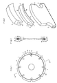
- a diamond saw blade Referring to Figs. 1, 2, and 3, there is shown a diamond saw blade.
- the body of this blade is indicated by numeral 1, and takes a disklike form.
- the body 1 is made of iron and has been quenched.
- a plurality of notches 2 are equally or arbitrarily spaced apart from each other circumferentially in the outer periphery of the body 1.
- An installation portion 3 to which an interposed member 4 is attached is formed between each two successive notches 2.
- Each interposed member 4 is inseparably mounted to the outer periphery of each installation portion 3 by inert-gas tungsten arc welding or laser welding. As best shown in Fig.
- each interposed member 4 is composed of a slender plate 4a for rigid mounting and a support ridge 5 formed integrally with the plate 4a and extending on the outer surface of the plate 4a over its whole length.
- the plate 4a is curved so as to correspond to the arc-shaped outer fringe of the installation portion 3 of the body 1.
- a pair of first installation surfaces 6 is formed on each side of the ridge 5 on the outer surface of the plate 4a.
- a pair of second installation surfaces 7 is formed on each side surface of the ridge 5.
- a third installation surface 8 is formed on the top, outer surface of the ridge 5.
- Each interposed member 4 is made of iron, cobalt, manganese, chronium, nickel, brass, copper, or other material. The installation surfaces 6, 7, 8 are all finished roughly.
- Segments 9 are firmly attached to the outer side surface of each interposed member 4. As can be seen from Fig. 2, each segment 9 is made somewhat thicker than the body 1, and is provided with a groove 10 extending on the inner side of the segment 9 over the whole length of the segment. The groove 10 is so dimensioned that the protrusion 5 of each interposed member 4 is fitted into it.
- Each segment 9 is made of a bronze alloy, an alloy of cobalt, copper, and other elements, a tungsten alloy, or other alloy. Diamond dust has been added to the material which has been sintered. Sufficient hardness is imparted to each segment 9 to prevent it from becoming chipped while it is being machined.
- each segment 9 is attached to the body 1 .
- diamond dust is added to powdered metal or metal compound.
- this mixture is sintered to form each segment 9.
- one interposed member 4 which has been already formed is placed in contact with the inner side surface of each segment 9 to inseparably mount the segment 9 to the interposed member 4 in such a way that the support ridge 5 of the member 4 is fitted in the groove 10 in the segment 9.
- the temperature at which the powdered metal or metal compound is heated during the sintering operation varies from material to material. When the material is a bronze alloy, the temperature is approximately 650°C. When it is a cobalt alloy, the temperature ranges from about 750°C to 800°C.
- each member 4 is rigidly fixed to the outer periphery of the body 1 by inert-gas tungsten arc welding, inert gas arc welding using a consumable electrode, laser welding, or other process.
- the segments 9 are fastened to the interposed members 4 by sintering and then the members 4 are welded to the body 1. Therefore, it is unlikely that the stress remaining inside of the body 1 is released by the heating during sintering, thereby deforming the body 1. Also, since the segments 9 are not directly attached to the body 1, cracking does not take place in heat-affected zones in the segments 9. In addition, since the segments 9 are joined to the interposed member 4 by sintering, there exists no possibility that the joined portions are molten by the heat produced when the saw blade is in use. Consequently, the segments 9 are prevented from coming off the interposed members 4. Furthermore, as the installation surfaces 6-8 on the interposed members 4 are made rough , these surfaces are in contact with the segments 9 with increased area of contact.
- the present invention prevents the body of a saw blade or the like from being deformed when segments are mounted to it. Also, it is unlikely that the segments come off the body or become damaged when the blade is in use. Further, the blade is relatively cheap to manufacture.
Landscapes
- Engineering & Computer Science (AREA)
- Mechanical Engineering (AREA)
- Mining & Mineral Resources (AREA)
- Polishing Bodies And Polishing Tools (AREA)
- Processing Of Stones Or Stones Resemblance Materials (AREA)
Claims (6)
- Un outil de coupe avec un support (1) et des segments de coupe (9) sur des points d'appui du support (1), caractérisé en ce que pour chaque point d'appui est prévu un organe (4) correspondant et situé au milieu, avec une platine (4a) et une nervure (5) et une multitude des surfaces d'appui rugueuses (6, 7, 8), où chaque segment (9) est fritté sur un organe intermédiaire (4) correspondant et ce le long chacune des surfaces d'appui (6, 7, 8) et ce dans cette forme que les segments (9) sont aménagés séparément du support (1) sur les pla ques (4a) et qu'après ce frittage chaque organe intermédiaire est soudé sur la surface d'appui correspondante et ce de manière à ce que seulement une surface de fond de la platine (4a) touche le point d'appui.
- Un outil de coupe selon la revendication 1, caractérisé en ce que chacune des surfaces d'appui (6. 7. 9) est rendue rugueuse.
- Un outil de coupe selon la revendication 1 ou 2, caractérisé en ce qu'au moins une des surfaces d'appui (6, 7 8) des organes intermédiaires est moletée.
- Un outil de coupe selon la revendication 1 ou 2, caractérisé en ce qu'au moins une des surfaces d'appui (6, 7 8) des organes intermédiaires est dentelée.
- Un outil de coupe selon la revendication 1 ou 2, caractérisé en ce que la nervure d'appui (5) présente une section en queue d'aronde et qu'une rainure (10) dans chaque segment (9) présente une section correspondante.
- Un outil de coupe selon la revendication 1, caractérisé en ce que la surface externe de chaque platine (4a) et la surface interne de chaque segment (9) sont dentelées pour constituer une surface d'appui (6a)
Applications Claiming Priority (2)
| Application Number | Priority Date | Filing Date | Title |
|---|---|---|---|
| JP257918/84 | 1984-12-06 | ||
| JP59257918A JPS61136774A (ja) | 1984-12-06 | 1984-12-06 | 切削工具のセグメントの取付け方法 |
Publications (3)
| Publication Number | Publication Date |
|---|---|
| EP0183902A2 EP0183902A2 (fr) | 1986-06-11 |
| EP0183902A3 EP0183902A3 (en) | 1988-07-20 |
| EP0183902B1 true EP0183902B1 (fr) | 1991-12-18 |
Family
ID=17312998
Family Applications (1)
| Application Number | Title | Priority Date | Filing Date |
|---|---|---|---|
| EP85106740A Expired EP0183902B1 (fr) | 1984-12-06 | 1985-05-31 | Procédé pour attacher des segments à un outil de découpage |
Country Status (4)
| Country | Link |
|---|---|
| US (1) | US4727778A (fr) |
| EP (1) | EP0183902B1 (fr) |
| JP (1) | JPS61136774A (fr) |
| DE (1) | DE3584951D1 (fr) |
Families Citing this family (22)
| Publication number | Priority date | Publication date | Assignee | Title |
|---|---|---|---|---|
| JPS6322274A (ja) * | 1986-07-10 | 1988-01-29 | Noritake Dia Kk | ダイヤモンド工具の製造方法 |
| DE3724913A1 (de) * | 1987-07-28 | 1989-02-09 | Richard Hahn Diamant Werkzeuge | Verfahren zur herstellung eines diamant-bandsaegeblattes und nach dem verfahren hergestelltes diamant-bandsaegeblatt |
| DE3738492A1 (de) * | 1987-11-12 | 1989-05-24 | Wagner Maschf Gustav | Verfahren zum befestigen von hss-schneiden oder dgl. an einem werkzeug-tragelement, sowie nach diesem verfahren hergestellte werkzeuge |
| JPH0541667U (ja) * | 1991-11-07 | 1993-06-08 | 株式会社カケン | 円鋸におけるダイヤモンドチツプの固着構造 |
| JPH06190731A (ja) * | 1992-11-05 | 1994-07-12 | General Electric Co <Ge> | 高トルクの締着具を備えた研磨工具用インサート |
| JPH074934A (ja) * | 1993-02-12 | 1995-01-10 | General Electric Co <Ge> | 結晶性物体の分級・選別 |
| US5650059A (en) * | 1995-08-11 | 1997-07-22 | Credo Tool Company | Method of making cemented carbide substrate |
| US6286406B1 (en) | 1996-02-12 | 2001-09-11 | Credo Tool Company | Injection molded carbide cutting insert |
| US5809848A (en) * | 1996-02-12 | 1998-09-22 | Credo Tool Company | Method of making a carbide cutting insert |
| WO1999055506A1 (fr) * | 1998-04-24 | 1999-11-04 | Umberto Ferri | Appareil a tailler la pierre utilisant un cable dentele portant des elements de coupe en forme de chaines |
| US6298762B1 (en) | 1998-08-06 | 2001-10-09 | Larue John D. | Saw blade with inserted multi-tooth arcs |
| US8146474B2 (en) * | 2004-02-17 | 2012-04-03 | Indigo Innovators, Inc. | Wood cutting saw chain and replaceable cutting members |
| US20070169605A1 (en) * | 2006-01-23 | 2007-07-26 | Szymanski David A | Components having sharp edge made of sintered particulate material |
| US7836808B2 (en) * | 2006-01-23 | 2010-11-23 | Szymanski David A | Safety chain and rotational devices and replaceable teeth therefor |
| DE102007016207B3 (de) * | 2007-04-04 | 2008-07-03 | Rattunde & Co Gmbh | Sägeblatt |
| CN100496897C (zh) * | 2007-05-08 | 2009-06-10 | 广东奔朗超硬材料制品有限公司 | 磨边轮及其制作工艺 |
| DE102011005012A1 (de) * | 2011-03-03 | 2012-09-06 | Robert Bosch Gmbh | Werkzeugmaschinentrennvorrichtung |
| US9833785B2 (en) * | 2012-12-17 | 2017-12-05 | Kooima Company | Method of making a processor disk |
| US20200156167A1 (en) * | 2017-06-12 | 2020-05-21 | Husqvarna Ab | Cutting tool and a method for producing the cutting tool |
| CN111975659B (zh) * | 2018-07-24 | 2022-05-17 | 江苏赛扬精工科技有限责任公司 | 单斜边结构冷锯砂轮的制备方法 |
| DE102018120243B4 (de) * | 2018-08-20 | 2020-04-23 | Credé Vermögensverwaltungs-GmbH + Co. KG | Verfahren zum Fügen von Hartstoffkörpern an Zähne eines Sägeblatts sowie Sägeblatt |
| CN118906250A (zh) * | 2024-07-22 | 2024-11-08 | 湖北万可金刚石科技有限公司 | 一种金刚石锯片刀头及其生产工艺 |
Family Cites Families (11)
| Publication number | Priority date | Publication date | Assignee | Title |
|---|---|---|---|---|
| US2589357A (en) * | 1949-04-13 | 1952-03-18 | Super Cut | Diamond type tooth for rotary stone cutting saws |
| FR1026618A (fr) * | 1950-10-27 | 1953-04-29 | Perfectionnements aux disques tronçonneurs abrasifs | |
| GB815420A (en) * | 1956-08-27 | 1959-06-24 | Norton Grinding Wheel Co Ltd | Diamond cut-off wheel |
| US3048160A (en) * | 1960-09-26 | 1962-08-07 | Trurun Inc | Attachment of cutting elements to wear resistant blades |
| FR1281493A (fr) * | 1960-12-13 | 1962-01-12 | Disque à couper | |
| NL286475A (fr) * | 1961-12-11 | |||
| JPS4937957B1 (fr) * | 1970-12-05 | 1974-10-14 | ||
| DE2323242C3 (de) * | 1973-05-09 | 1978-03-09 | Robert Bosch Gmbh, 7000 Stuttgart | Verfahren und Vorrichtung zur Herstellung einer verschleißfesten Hartmetalischicht auf einem Metallgegenstand |
| DE2853650A1 (de) * | 1978-12-13 | 1980-06-19 | Tusch Kg Diamant | Trennscheibe |
| JPS5851961B2 (ja) * | 1979-03-20 | 1983-11-19 | 東レ株式会社 | 共重合体の製造方法 |
| JPS58132465A (ja) * | 1982-02-03 | 1983-08-06 | Shinnitsusan Daiyamondo Kogyo Kk | メタルボンド砥石のセグメントチツプ |
-
1984
- 1984-12-06 JP JP59257918A patent/JPS61136774A/ja active Pending
-
1985
- 1985-05-31 DE DE8585106740T patent/DE3584951D1/de not_active Expired - Lifetime
- 1985-05-31 EP EP85106740A patent/EP0183902B1/fr not_active Expired
-
1986
- 1986-03-17 US US06/841,029 patent/US4727778A/en not_active Expired - Fee Related
Also Published As
| Publication number | Publication date |
|---|---|
| EP0183902A2 (fr) | 1986-06-11 |
| EP0183902A3 (en) | 1988-07-20 |
| DE3584951D1 (de) | 1992-01-30 |
| JPS61136774A (ja) | 1986-06-24 |
| US4727778A (en) | 1988-03-01 |
Similar Documents
| Publication | Publication Date | Title |
|---|---|---|
| EP0183902B1 (fr) | Procédé pour attacher des segments à un outil de découpage | |
| EP0718462B1 (fr) | Elément coupant pour trépan de forage et procédé de montage d'un élément coupant sur un trépan de forage | |
| US4686080A (en) | Composite compact having a base of a hard-centered alloy in which the base is joined to a substrate through a joint layer and process for producing the same | |
| US4225322A (en) | Composite compact components fabricated with high temperature brazing filler metal and method for making same | |
| US3800633A (en) | Method of manufacturing bimetallic high-speed cutting tools | |
| US6638153B2 (en) | Diamond saw blade equipped with undercut preventing tip | |
| US5183362A (en) | Cutting tool assembly | |
| US4520881A (en) | Tool component | |
| US4319707A (en) | Brazing apparatus to manufacture composite compact components | |
| JPH09158657A (ja) | カッタービット及びカッタービットブロックアセンブリ | |
| JP4244072B2 (ja) | マシンツール及びその製造方法 | |
| EP0163914A1 (fr) | Méthode de soudage pour segments de coupe | |
| US5144867A (en) | Method of making a chain saw guide bar | |
| US4947019A (en) | Composite electrode for resistance welding | |
| US4793231A (en) | Composite tool and method of making | |
| JPH0228428B2 (fr) | ||
| US4319507A (en) | Shearing device | |
| US20020178890A1 (en) | Cutting tool | |
| JPS62218069A (ja) | 切削工具のセグメントの取付け方法 | |
| US20050133487A1 (en) | Cutting tool and a method for the manufacture thereof | |
| WO2002051605A1 (fr) | Scie antibruit equipee d'un materiau antivibration | |
| JPH0111394Y2 (fr) | ||
| JPS637468Y2 (fr) | ||
| JPS637467Y2 (fr) | ||
| JPS6334816Y2 (fr) |
Legal Events
| Date | Code | Title | Description |
|---|---|---|---|
| PUAI | Public reference made under article 153(3) epc to a published international application that has entered the european phase |
Free format text: ORIGINAL CODE: 0009012 |
|
| AK | Designated contracting states |
Kind code of ref document: A2 Designated state(s): BE CH DE FR GB LI |
|
| PUAL | Search report despatched |
Free format text: ORIGINAL CODE: 0009013 |
|
| AK | Designated contracting states |
Kind code of ref document: A3 Designated state(s): BE CH DE FR GB LI |
|
| 17P | Request for examination filed |
Effective date: 19880811 |
|
| 17Q | First examination report despatched |
Effective date: 19890913 |
|
| GRAA | (expected) grant |
Free format text: ORIGINAL CODE: 0009210 |
|
| AK | Designated contracting states |
Kind code of ref document: B1 Designated state(s): BE CH DE FR GB LI |
|
| REF | Corresponds to: |
Ref document number: 3584951 Country of ref document: DE Date of ref document: 19920130 |
|
| ET | Fr: translation filed | ||
| PLBE | No opposition filed within time limit |
Free format text: ORIGINAL CODE: 0009261 |
|
| STAA | Information on the status of an ep patent application or granted ep patent |
Free format text: STATUS: NO OPPOSITION FILED WITHIN TIME LIMIT |
|
| 26N | No opposition filed | ||
| PGFP | Annual fee paid to national office [announced via postgrant information from national office to epo] |
Ref country code: GB Payment date: 19950512 Year of fee payment: 11 |
|
| PGFP | Annual fee paid to national office [announced via postgrant information from national office to epo] |
Ref country code: FR Payment date: 19950517 Year of fee payment: 11 |
|
| PGFP | Annual fee paid to national office [announced via postgrant information from national office to epo] |
Ref country code: CH Payment date: 19950519 Year of fee payment: 11 |
|
| PGFP | Annual fee paid to national office [announced via postgrant information from national office to epo] |
Ref country code: DE Payment date: 19950526 Year of fee payment: 11 |
|
| PGFP | Annual fee paid to national office [announced via postgrant information from national office to epo] |
Ref country code: BE Payment date: 19950609 Year of fee payment: 11 |
|
| PG25 | Lapsed in a contracting state [announced via postgrant information from national office to epo] |
Ref country code: LI Effective date: 19960531 Ref country code: GB Effective date: 19960531 Ref country code: CH Effective date: 19960531 Ref country code: BE Effective date: 19960531 |
|
| BERE | Be: lapsed |
Owner name: OMI KOGYO CO. LTD Effective date: 19960531 |
|
| REG | Reference to a national code |
Ref country code: CH Ref legal event code: PL |
|
| GBPC | Gb: european patent ceased through non-payment of renewal fee |
Effective date: 19960531 |
|
| PG25 | Lapsed in a contracting state [announced via postgrant information from national office to epo] |
Ref country code: FR Effective date: 19970131 |
|
| PG25 | Lapsed in a contracting state [announced via postgrant information from national office to epo] |
Ref country code: DE Effective date: 19970201 |
|
| REG | Reference to a national code |
Ref country code: FR Ref legal event code: ST |