EP0183932B1 - Générateur d'impulsions où le mouvement du générateur est converti en un train d'impulsions - Google Patents
Générateur d'impulsions où le mouvement du générateur est converti en un train d'impulsions Download PDFInfo
- Publication number
- EP0183932B1 EP0183932B1 EP85112047A EP85112047A EP0183932B1 EP 0183932 B1 EP0183932 B1 EP 0183932B1 EP 85112047 A EP85112047 A EP 85112047A EP 85112047 A EP85112047 A EP 85112047A EP 0183932 B1 EP0183932 B1 EP 0183932B1
- Authority
- EP
- European Patent Office
- Prior art keywords
- flip
- flop
- pulses
- input
- series
- Prior art date
- Legal status (The legal status is an assumption and is not a legal conclusion. Google has not performed a legal analysis and makes no representation as to the accuracy of the status listed.)
- Expired
Links
- 230000001419 dependent effect Effects 0.000 claims abstract description 4
- 230000010363 phase shift Effects 0.000 claims abstract 2
- 238000011156 evaluation Methods 0.000 description 9
- 238000001208 nuclear magnetic resonance pulse sequence Methods 0.000 description 4
- 230000000630 rising effect Effects 0.000 description 4
- 238000010586 diagram Methods 0.000 description 3
- 238000005265 energy consumption Methods 0.000 description 2
- 238000005259 measurement Methods 0.000 description 2
- 230000002457 bidirectional effect Effects 0.000 description 1
- 230000000717 retained effect Effects 0.000 description 1
Images


Classifications
-
- H—ELECTRICITY
- H03—ELECTRONIC CIRCUITRY
- H03M—CODING; DECODING; CODE CONVERSION IN GENERAL
- H03M1/00—Analogue/digital conversion; Digital/analogue conversion
- H03M1/12—Analogue/digital converters
- H03M1/22—Analogue/digital converters pattern-reading type
- H03M1/24—Analogue/digital converters pattern-reading type using relatively movable reader and disc or strip
- H03M1/28—Analogue/digital converters pattern-reading type using relatively movable reader and disc or strip with non-weighted coding
- H03M1/30—Analogue/digital converters pattern-reading type using relatively movable reader and disc or strip with non-weighted coding incremental
-
- G—PHYSICS
- G01—MEASURING; TESTING
- G01P—MEASURING LINEAR OR ANGULAR SPEED, ACCELERATION, DECELERATION, OR SHOCK; INDICATING PRESENCE, ABSENCE, OR DIRECTION, OF MOVEMENT
- G01P13/00—Indicating or recording presence, absence, or direction, of movement
- G01P13/02—Indicating direction only, e.g. by weather vane
- G01P13/04—Indicating positive or negative direction of a linear movement or clockwise or anti-clockwise direction of a rotational movement
- G01P13/045—Indicating positive or negative direction of a linear movement or clockwise or anti-clockwise direction of a rotational movement with speed indication
Definitions
- the invention relates to a pulse generator for converting the movement of a sensor into a pulse sequence that is dependent on the direction of movement according to the preamble of patent claim 1.
- Such pulse generators are mostly used to record rotary movements.
- Ferraris counters can be equipped with such pulse generators, which then emit a pulse for every full revolution or for integral parts of a revolution of the rotor disk.
- Each pulse then corresponds to a certain amount of the measured energy, determined by the counter constants.
- the energy consumption in this time period can be determined by counting the pulses delivered over a predetermined time period.
- additional impulses can be emitted which do not correspond to the energy to be measured and therefore lead to an incorrect display of the energy consumption.
- the invention has for its object to perform a pulse generator of the type mentioned so that false impulses when changing the direction of movement, even with pendulum movements, can be avoided within a certain range with little effort.
- an additional evaluation circuit can be provided according to a further development of the invention.
- FIG. 1 shows a basic circuit diagram of the arrangement.
- a pulse generator 1 contains a sensor disc 1 a, which performs a rotary movement and has a wing in the example.
- two coils 1b and 1c which are offset with respect to one another are arranged as sensors, each of which is supplied with alternating voltage by a converter circuit 1d or 1e.
- the inductance of the sensors 1 b and 1 c depends on whether they are currently in the area of a wing of the encoder disk 1a. This is evaluated by the converter circuits 1 d and 1 e, which always emit a "1" signal at the outputs A and B when the assigned sensor coil 1 b or 1c lies over a wing of the encoder disk 1a.
- the converter circuits 1d and 1e also have outputs A and B, which emit the inverted signal of the outputs A and B, respectively.
- a corresponding pulse generator could of course not only be set up for rotary movements, but also for linear movements if the rotating encoder disk is replaced by a straight arrangement with corresponding teeth.
- the output A of the converter circuit 1d is connected to the clock input of the first flip-flop 2a and the output A is connected to the clock input of the second JK flip-flop 2b.
- the output B of the converter circuit 1 e is connected to the J input of the second JK flip-flop 2b and the output B to the J input of the first JK flip-flop 2a.
- the desired pulse sequence for rotation in the forward direction is present.
- the pulses during reverse rotation can also be detected.
- the output A of the converter circuit 1d is connected to the clock input of a third JK flip-flop 3a and the output A is connected to the clock input of a fourth JK flip-flop 3b.
- the output B of the converter circuit 1e is connected to the J input of the third JK flip-flop 3a and the output B to the J input of the fourth JK flip-flop 3b.
- the non-inverting output Q of the fourth JK flip-flop 3b is with the clock-independent reset input R of the third JK flip-flop 3a and the inverting output Q of the third JK flip-flop 3a is with the clock-independent reset input of the fourth JK flip-flop 3a 3b connected.
- a "0" signal is present at the K inputs of the two JK flip-flops 2a and 2b.
- the desired pulses are present when the encoder disk rotates backwards.
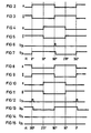
- the JK flip-flop 2a With each rising edge of signal A, the JK flip-flop 2a is set, since a "1" signal is present at the J input with the signal leg. The output signal Q 2a thus goes to "1". With the rising edge of signal A, the second JK flip-flop 2b is set, since a "1" signal is present at its J input with signal B. The output signal Q 2b thus becomes “1", so that the first JK flip-flop 2a is reset via the reset input R, ie the output signal Q 2a changes to "0". Since the output signal (not shown) at the inverting output Q of the first flip-flop 2a simultaneously changes to "1", the second JK flip-flop 2b is reset again via its reset input R. Thus, the evaluation circuit 2 in turn emits a pulse for each pulse of the pulse generator 1, provided that the encoder disc 1a rotates in the forward direction. The angular resolution given by the sensor is retained.
- the third JK flip-flop 3a is set with each positive edge of the signal A, since a "1" signal is present at its J input with the signal B. With every rising edge of the signal ⁇ , i.e. Every falling edge of signal A, the fourth JK flip-flop 3b is set, since a "1" signal is present at its J input with signal B at the same time. With the "1" signal present at the output Q of the JK flip-flop 3b, the third JK flip-flop 3a is reset via the reset input R. The fourth JK flip-flop 3b is in turn reset by the "1" signal present at the output Q of the third JK flip-flop 3a.
- the evaluation circuit 3 therefore outputs an output pulse for each pulse of the encoder circuit 1, provided that the encoder disk 1a rotates in the reverse direction.
- FIGS. 14 and 15 also show the output signals Q 2a and Q 2b at the Q outputs of the first and second JK flip-flops 2a and 2b. It can be seen that none of these JK flip-flops is set during reverse rotation. Setting the first JK flip-flop 2a is only possible on positive edges of signal A. However, the signal B present at its J input is always "0", so that no setting takes place. In the same way, the signal B present at the J input of the second JK flip-flop 2b is always "0" if that has a rising edge at its clock input signal A.
- the pulse generator described therefore emits pulses at separate outputs when rotating forwards and backwards.
- the first JK flip-flop 2a is set with the first edge of the signal A, since the output signal B is "1" at the same time.
- the state of the first flip-flop 2a remains unchanged until the second JK flip-flop 2b is set. This is only the case after a further forward rotation in area III, since in this case a positive signal edge of the signal ⁇ at the clock input of the second JK flip-flop 2b with a "1" signal of the signal B at the J input of the second JK flip -Flops meets.
- the first JK flip-flop 2a is thus reset via its reset input R and then also the second JK flip-flop 2b.
Landscapes
- Physics & Mathematics (AREA)
- General Physics & Mathematics (AREA)
- Engineering & Computer Science (AREA)
- Theoretical Computer Science (AREA)
- Transmission And Conversion Of Sensor Element Output (AREA)
- Indicating Or Recording The Presence, Absence, Or Direction Of Movement (AREA)
- Ultra Sonic Daignosis Equipment (AREA)
- Investigating Or Analyzing Materials By The Use Of Ultrasonic Waves (AREA)
- Analogue/Digital Conversion (AREA)
- Radar Systems Or Details Thereof (AREA)
- Burglar Alarm Systems (AREA)
Claims (2)
Priority Applications (1)
| Application Number | Priority Date | Filing Date | Title |
|---|---|---|---|
| AT85112047T ATE42837T1 (de) | 1984-10-08 | 1985-09-24 | Impulsgeber zum umsetzen der bewegung eines gebers in eine impulsfolge. |
Applications Claiming Priority (2)
| Application Number | Priority Date | Filing Date | Title |
|---|---|---|---|
| DE3436909 | 1984-10-08 | ||
| DE3436909 | 1984-10-08 |
Publications (2)
| Publication Number | Publication Date |
|---|---|
| EP0183932A1 EP0183932A1 (fr) | 1986-06-11 |
| EP0183932B1 true EP0183932B1 (fr) | 1989-05-03 |
Family
ID=6247404
Family Applications (1)
| Application Number | Title | Priority Date | Filing Date |
|---|---|---|---|
| EP85112047A Expired EP0183932B1 (fr) | 1984-10-08 | 1985-09-24 | Générateur d'impulsions où le mouvement du générateur est converti en un train d'impulsions |
Country Status (4)
| Country | Link |
|---|---|
| EP (1) | EP0183932B1 (fr) |
| AT (1) | ATE42837T1 (fr) |
| DE (1) | DE3569987D1 (fr) |
| ES (1) | ES8609700A1 (fr) |
Families Citing this family (3)
| Publication number | Priority date | Publication date | Assignee | Title |
|---|---|---|---|---|
| US4663589A (en) * | 1985-02-11 | 1987-05-05 | Sensor Technologies, Inc. | Displacement sensor having multiplexed dual tank circuits |
| EP1580561A1 (fr) * | 2004-03-24 | 2005-09-28 | Alcatel | Procede et dispositif pour la détermination de la direction de mouvement avec tolérance aux erreurs |
| RU2427956C1 (ru) * | 2010-04-13 | 2011-08-27 | Государственное образовательное учреждение высшего профессионального образования Московский государственный индустриальный университет | Преобразователь линейных перемещений в цифровой код |
-
1985
- 1985-09-24 EP EP85112047A patent/EP0183932B1/fr not_active Expired
- 1985-09-24 AT AT85112047T patent/ATE42837T1/de not_active IP Right Cessation
- 1985-09-24 DE DE8585112047T patent/DE3569987D1/de not_active Expired
- 1985-10-07 ES ES547646A patent/ES8609700A1/es not_active Expired
Also Published As
| Publication number | Publication date |
|---|---|
| DE3569987D1 (en) | 1989-06-08 |
| ES547646A0 (es) | 1986-07-16 |
| ATE42837T1 (de) | 1989-05-15 |
| ES8609700A1 (es) | 1986-07-16 |
| EP0183932A1 (fr) | 1986-06-11 |
Similar Documents
| Publication | Publication Date | Title |
|---|---|---|
| EP0349716B1 (fr) | Système de détection de la position de parties mobiles d'une machine | |
| DE2553806C3 (de) | Schaltungsanordnung zur digitalen Messung der Periodendauer einer Wechselspannung | |
| EP0233618A2 (fr) | Détecteur de mouvement | |
| EP0340481B1 (fr) | Arrangement pour dépouiller les signaux d'un capteur incrémenteil | |
| DE3318351C2 (de) | Schaltungsanordnung für eine drehzahl- und drehrichtungsabhängige Auswerteschaltung eines inkrementalen Drehrichtungsimpulsgebers | |
| EP0183932B1 (fr) | Générateur d'impulsions où le mouvement du générateur est converti en un train d'impulsions | |
| EP0062698B1 (fr) | Circuit d'évaluation pour un transducteur de vitesse de rotation | |
| EP0203275A2 (fr) | Capteur incrémentiel | |
| DE102007061246A1 (de) | Magneterfassungseinrichtung | |
| DE19730806A1 (de) | Einrichtung zur Signalauswertung bei Inkrementalgebern | |
| DE2353039A1 (de) | Messanordnung fuer die winkelstellung eines magnetfeldes | |
| DE3123002A1 (de) | Verfahren und einrichtung zur drehzahlmessung einer mit einem rotierenden impulsgeber gekuppelten welle | |
| DE3407590C1 (de) | Fotoelektrischer Impulsgeber | |
| DE2621179C2 (de) | Schaltungsanordnung zur Erfassung der Drehrichtung rotierender Teile | |
| DE1773559C3 (de) | Anordnung zur Erzeugung von Impulsen, welche ein genaues MaB für jede Umdrehung eines rotierenden Elementes sind | |
| DE3330500C2 (de) | Schaltungsanordnung zur Störimpulsunterdrückung | |
| EP0310764B1 (fr) | Circuit d'évaluation pour impulsions | |
| DE3027127C2 (fr) | ||
| DE3513343C2 (fr) | ||
| DE2735325A1 (de) | Verfahren zur messwertermittlung bei inkrementalen weg- und winkelmessystemen | |
| DE4100866C1 (fr) | ||
| CH395559A (de) | Digitale Winkelmesseinrichtung | |
| DE3815535A1 (de) | Verfahren und anordnung zur messung der drehzahl einer maschine | |
| DE2252159C3 (de) | Schaltungsanordnung zum Bestimmen der Drehzahl und der Drehrichtung einer Welle | |
| DE10126077B4 (de) | Auswerteschaltung |
Legal Events
| Date | Code | Title | Description |
|---|---|---|---|
| PUAI | Public reference made under article 153(3) epc to a published international application that has entered the european phase |
Free format text: ORIGINAL CODE: 0009012 |
|
| AK | Designated contracting states |
Kind code of ref document: A1 Designated state(s): AT CH DE FR GB IT LI SE |
|
| 17P | Request for examination filed |
Effective date: 19860826 |
|
| 17Q | First examination report despatched |
Effective date: 19880113 |
|
| GRAA | (expected) grant |
Free format text: ORIGINAL CODE: 0009210 |
|
| AK | Designated contracting states |
Kind code of ref document: B1 Designated state(s): AT CH DE FR GB IT LI SE |
|
| REF | Corresponds to: |
Ref document number: 42837 Country of ref document: AT Date of ref document: 19890515 Kind code of ref document: T |
|
| REF | Corresponds to: |
Ref document number: 3569987 Country of ref document: DE Date of ref document: 19890608 |
|
| ET | Fr: translation filed | ||
| ITF | It: translation for a ep patent filed | ||
| GBT | Gb: translation of ep patent filed (gb section 77(6)(a)/1977) | ||
| PLBE | No opposition filed within time limit |
Free format text: ORIGINAL CODE: 0009261 |
|
| STAA | Information on the status of an ep patent application or granted ep patent |
Free format text: STATUS: NO OPPOSITION FILED WITHIN TIME LIMIT |
|
| 26N | No opposition filed | ||
| PGFP | Annual fee paid to national office [announced via postgrant information from national office to epo] |
Ref country code: GB Payment date: 19910822 Year of fee payment: 7 |
|
| PGFP | Annual fee paid to national office [announced via postgrant information from national office to epo] |
Ref country code: AT Payment date: 19910828 Year of fee payment: 7 |
|
| PGFP | Annual fee paid to national office [announced via postgrant information from national office to epo] |
Ref country code: SE Payment date: 19910911 Year of fee payment: 7 |
|
| PGFP | Annual fee paid to national office [announced via postgrant information from national office to epo] |
Ref country code: FR Payment date: 19910917 Year of fee payment: 7 |
|
| ITTA | It: last paid annual fee | ||
| PGFP | Annual fee paid to national office [announced via postgrant information from national office to epo] |
Ref country code: DE Payment date: 19911127 Year of fee payment: 7 |
|
| PGFP | Annual fee paid to national office [announced via postgrant information from national office to epo] |
Ref country code: CH Payment date: 19911216 Year of fee payment: 7 |
|
| PG25 | Lapsed in a contracting state [announced via postgrant information from national office to epo] |
Ref country code: GB Effective date: 19920924 Ref country code: AT Effective date: 19920924 |
|
| PG25 | Lapsed in a contracting state [announced via postgrant information from national office to epo] |
Ref country code: SE Effective date: 19920925 |
|
| PG25 | Lapsed in a contracting state [announced via postgrant information from national office to epo] |
Ref country code: LI Effective date: 19920930 Ref country code: CH Effective date: 19920930 |
|
| GBPC | Gb: european patent ceased through non-payment of renewal fee |
Effective date: 19920924 |
|
| PG25 | Lapsed in a contracting state [announced via postgrant information from national office to epo] |
Ref country code: FR Effective date: 19930528 |
|
| REG | Reference to a national code |
Ref country code: CH Ref legal event code: PL |
|
| PG25 | Lapsed in a contracting state [announced via postgrant information from national office to epo] |
Ref country code: DE Effective date: 19930602 |
|
| REG | Reference to a national code |
Ref country code: FR Ref legal event code: ST |
|
| EUG | Se: european patent has lapsed |
Ref document number: 85112047.7 Effective date: 19930406 |