EP0183942B1 - Moule étagé pour moulage par injection-soufflage - Google Patents
Moule étagé pour moulage par injection-soufflage Download PDFInfo
- Publication number
- EP0183942B1 EP0183942B1 EP85112814A EP85112814A EP0183942B1 EP 0183942 B1 EP0183942 B1 EP 0183942B1 EP 85112814 A EP85112814 A EP 85112814A EP 85112814 A EP85112814 A EP 85112814A EP 0183942 B1 EP0183942 B1 EP 0183942B1
- Authority
- EP
- European Patent Office
- Prior art keywords
- core
- mold
- mandrel
- blow
- ejection
- Prior art date
- Legal status (The legal status is an assumption and is not a legal conclusion. Google has not performed a legal analysis and makes no representation as to the accuracy of the status listed.)
- Expired
Links
- 238000007664 blowing Methods 0.000 title 1
- 238000002347 injection Methods 0.000 title 1
- 239000007924 injection Substances 0.000 title 1
- 238000000465 moulding Methods 0.000 title 1
Images

Classifications
-
- B—PERFORMING OPERATIONS; TRANSPORTING
- B29—WORKING OF PLASTICS; WORKING OF SUBSTANCES IN A PLASTIC STATE IN GENERAL
- B29C—SHAPING OR JOINING OF PLASTICS; SHAPING OF MATERIAL IN A PLASTIC STATE, NOT OTHERWISE PROVIDED FOR; AFTER-TREATMENT OF THE SHAPED PRODUCTS, e.g. REPAIRING
- B29C49/00—Blow-moulding, i.e. blowing a preform or parison to a desired shape within a mould; Apparatus therefor
- B29C49/28—Blow-moulding apparatus
- B29C49/30—Blow-moulding apparatus having movable moulds or mould parts
- B29C49/32—Blow-moulding apparatus having movable moulds or mould parts moving "to and fro"
-
- B—PERFORMING OPERATIONS; TRANSPORTING
- B29—WORKING OF PLASTICS; WORKING OF SUBSTANCES IN A PLASTIC STATE IN GENERAL
- B29C—SHAPING OR JOINING OF PLASTICS; SHAPING OF MATERIAL IN A PLASTIC STATE, NOT OTHERWISE PROVIDED FOR; AFTER-TREATMENT OF THE SHAPED PRODUCTS, e.g. REPAIRING
- B29C2949/00—Indexing scheme relating to blow-moulding
- B29C2949/07—Preforms or parisons characterised by their configuration
- B29C2949/0715—Preforms or parisons characterised by their configuration the preform having one end closed
-
- B—PERFORMING OPERATIONS; TRANSPORTING
- B29—WORKING OF PLASTICS; WORKING OF SUBSTANCES IN A PLASTIC STATE IN GENERAL
- B29C—SHAPING OR JOINING OF PLASTICS; SHAPING OF MATERIAL IN A PLASTIC STATE, NOT OTHERWISE PROVIDED FOR; AFTER-TREATMENT OF THE SHAPED PRODUCTS, e.g. REPAIRING
- B29C49/00—Blow-moulding, i.e. blowing a preform or parison to a desired shape within a mould; Apparatus therefor
- B29C49/02—Combined blow-moulding and manufacture of the preform or the parison
- B29C49/06—Injection blow-moulding
-
- B—PERFORMING OPERATIONS; TRANSPORTING
- B29—WORKING OF PLASTICS; WORKING OF SUBSTANCES IN A PLASTIC STATE IN GENERAL
- B29C—SHAPING OR JOINING OF PLASTICS; SHAPING OF MATERIAL IN A PLASTIC STATE, NOT OTHERWISE PROVIDED FOR; AFTER-TREATMENT OF THE SHAPED PRODUCTS, e.g. REPAIRING
- B29C49/00—Blow-moulding, i.e. blowing a preform or parison to a desired shape within a mould; Apparatus therefor
- B29C49/08—Biaxial stretching during blow-moulding
- B29C49/087—Means for providing controlled or limited stretch ratio
Definitions
- the invention concerns a process for injection blow molding at least one hollow plastic article injecting molten plastic into a first injection mold to form a first parison on a first core, moving said parison on said core into a first blow mold adjacent to the first injection mold in side-by-side relationship therewith, expanding said parison on said core in said blow mold to form the hollow plastic articles, transferring said hollow plastic article on an ejection mandrel from said blow mold to a first ejection station and removing said hollow article from said ejection station, and an apparatus therefore, according to the preamble of claim 4.
- the US-A-3 819 3144 upon which, the preambles of the independent claims 1 and 4 are based, shows an injection mold, a blow mold and an ejection station in side-by-side relationship. Furthermore it shows a core and an ejection mandrel in side-by-side relationship. But this apparatus does not produce a plurality of articles in the same time and it operates relatively slowly.
- the solution of the above mentioned objects is characterized in that the first core and the first mandrel operate in overlapping cycles with a second core and a second mandrel whereby when said first core and first mandrel are located at said first injection mold and first blow mold, respectively, at the same time said second core and second mandrel are located at a position other than at a second injection mold arranged back-to-back to the first injection mold and a second blow mold arranged back-to-back to the first blow mold, respectively, and whereby said first core and first mandrel are then located at said first blow mold and first ejection station, respectively, at the same time said second core and second mandrel are located at a position other than at said second blow mold and a second ejection station arranged back-to-back to said first ejection station, respectively.
- the apparatus is characterized by the features as laid out in the characterizing portion of claim 4.
- said cores, blow molds and ejection stations comprise a first set and second set, respectively; and a corresponding third and fourth set of cores, mandrels, blow molds and ejection stations are provided adjacent and in line with the first and second set, respectively, with the blow molds and ejection stations in back-to-back relationship with each other and on opposite sides of said first and second injection molds.
- one locates said first core and first ejection mandrel at said first injection mold and first blow mold, respectively, while said second core and second ejection mandrel are at the same time located at said second blow mold and second ejection station, respectively.
- the third and fourth sets are simultaneously in corresponding positions with injection taking place simultaneously in two opposed injection molds. It is particularly advantageous to provide a common platen for the first and third cores and a common platen for the second and fourth cores with balanced motive means for both platens in order to use less force to move the platens.
- stack-molds are provided for injections conveniently and expeditiously enabling one or produce simultaneously twice as many parts in the same interval, thereby doubling the output.
- the overlapping cycle operation is especially expeditious and enables the process and apparatus to operate smoothly and efficiently.
- the operation enables convenient removal of the hollow articles in overlapping relationship whereby the articles may be expeditiously removed or ejected without jamming by first removing an article from one side of the stack and then from another side of the stack..
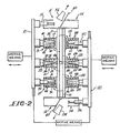
- injection station 10 the first injection station, is secured in platen 11.
- First and third blow stations 12 and 13 are also secured to platen 11 and are situated adjacent injection station 10 and in side-by-side relationship with respect thereto, with blow station 12 containing first blow mold 16 which may be split if desired being on one side of the injection station and blow station 13 containing third blow mold 17 which may be split if desired being on the other side.
- Blow molds 16 and 17 correspond to the shape of the hollow articles to be made.
- First and third ejection stations 14 and 15 are also secured to platen 11 and are situated adjacent the respective blow stations in side-by-side relationship with respect thereto, with first ejection station 14 situated adjacent first blow station 12 and third ejection station 15 situated adjacent third blow station 13.
- First core 20 is provided secured to movable platen 21 engageable with first injection station 10.
- the injection station 10 includes mold wall 22.
- Injection means 24 is in communication with the mold cavity and is connected to a source of hot flowable plastic (not shown) for forcing said hot formable plastic under pressure into the first mold cavity to form a parison therein, as parison 25.
- Core 20 is movable into and out of engagement with injection station 10 by movable platen 21 actuated by the motive means shown schematically in the drawings and in a cycle to be described in more detail hereinbelow.
- the movement of platen 21 may be accomplished by conventional means, shown only schematically in the drawings, which are capable of providing a clamping force between the two platens to keep them from separating during the injection step and the other steps which will be described below.
- the hot, newly formed parison 25 remains in the mold cavity until sufficiently cooled to be removed, if desired using cooling means 26 adjacent mold wall 22, as for example, by fluid circulation. If desired, such cooling means may also be provided in core 20. After such cooling of parison 25 the clamping force is released and platen 21 is moved away from platen 11 carrying with it core 20 and parison 25 adhered thereto as shown in the drawing. If a neck mold is used as to form a threaded neck portion the neck mold is openable by conventional means and remains closed during the formation of the parison, removal of the parison from the injection station and blowing, which also aids in retention of the parison on the core.
- parison 25 as well as the final hollow article has a base portion, a curved lip and outwardly flaring side walls extending from the base to lip.
- the curved lip may serve as an undercut to aid in retention of the parison on the core.
- Core 20 is provided with fluid passageway 33 connected to a source of fluid pressure for blowing the final article. If desired, a vacuum may be drawn through passageway 33 to aid in retention of the parison on the core.
- Core 20 with parison 25 thereon is then moved to first blow station 12 in a manner which first separates the parison from the mold wall 22 by moving the parison on core 20 axially in a straight path away from said mold wall at least until the parison clears the injection station, preferably followed by movement in a substantially arcuate path into axial alignment with first blow station 12 and first blow mold 16, preferably followed by moving the parison on the core axially in a straight path into blow mold 16.
- the preferred axial-arcuate-axial movements are fully disclosed in said copending US-A-618,956.
- Parison 25 is then expanded on core 20 in blow mold 16 by fluid pressure through passageway 33 to form hollow article 34.
- Figure 1 shows core 20 with parison 25 thereon removed from the injection station on its path between injection station 10 and blow station 12 and
- Figure 2 shows core 20 engaged with the injection station.
- core 20 is removed from blow station 12 leaving hollow article 34 remaining therein and returned to the injection station along paths corresponding to the path taken by core 20 from the injection station 10 to the blow mold 16.
- Third core 40 having fluid passageway 45 similar to passageway 33 is provided on movable platen 21 adjacent core 20 in side-by-side relationship with respect thereto.
- Third core 40 is engageable with injection station 10 when core 20 engages blow mold 16 to form a second parison in an overlapping cycle with respect to core 20.
- third core 40 engages injection station 10 to form a parison 25 in a manner similar to the formation of a parison on core 20 in the injection station 10.
- the formation of a parison on core 40 takes place while core 20 is in the blow mold 16 forming the hollow article.
- Core 40 carrying a parison 25 is then removed from the injection station and transferred to third blow station 13 and third blow mold 17 in a path corresponding to the transfer path of core 10 to first blow station 12 and first blow mold 17 for formation of an additional hollow article 34 in blow mold 17.
- the transfer of core 40 to blow mold 17 takes place simultaneously with the return of core 20 to injection station 10.
- Hollow article 34 corresponds in shape generally to parison 25 with an expanded configuration caused by the blowing step.
- the blown article 34 cools in contact with the walls of the blow mold which may contain cooling means 44, as for example for cooling by fluid circulation in a conventional manner, and may be retained in the blow mold after removal of the core therefrom.
- First ejection mandrel 50 and third ejection mandrel 51 are provided on movable platen 21 adjacent and in side-by-side relationship to cores 40 and 20, with first ejection mandrel 50 alongside core 20 and third ejection mandrel 51 alongside second core 40.
- ejection mandrels 50 and 51 move into engagement with said hollow articles in the blow molds along paths corresponding to the paths of cores 20 and 40.
- Mandrels 50 and 51 then disengage from the blow molds removing hollow articles 34 with them and move from the blow stations to the ejection stations along paths corresponding to the paths of cores 20 and 40.
- Removal of hollow article 34 onto the ejection mandrels may be assisted by a pusher means operatively associated with the blow molds for positively pushing article 34 away from the blow molds.
- ejection mandrels 50 and 51 may be provided with fluid passageways connected to a source of fluid pressure (not shown) which may be used to draw a vacuum and aid in removal of hollow article 34 from the respective blow molds.
- the final hollow article is then transferred to the respective ejection station, which may incorporate any suitable ejection means as a chute, suction tube or other conventional means to convey plastic articles.
- Removal of article 34 from the ejection mandrels 50 and 51 at ejection stations 14 and 15 may be assisted byfluid pressure fromthe ejection mandrels and also by a stripper means associated with the ejection mandrels. After removal of the hollow article 34 atthe ejection stations the cycle is repeated.
- the first cores and mandrels together with the first blow station and the first ejection station comprises the first set and the third cores and mandrels together with the third blow station and the third ejection station comprises the third set.
- a second injection station 110 is provided in back-to-back relationship with the first injection station 10.
- the second blow station 112 In side-by-side relationship with the second injection station is the second blow station 112 and in side-by-side relationship with the second blow station is the second ejection station 114, both of these elements being in back-to-back relationship with their counterparts in the first set.
- Fourth blow station 113 and the fourth ejection station 115 are provided situated back-to-back with their corresponding elements in the third set.
- Second injection station 110 functions serially with the second and fourth sets similar to first injection station 10.
- the second and fourth sets are carried by fixed platen 111 which may be joined to platen 11 if convenient.
- the second injection station may include heating or cooling elements 126 and includes mold wall 122.
- the second and fourth blow stations includes a second blow mold 116 and a fourth blow mold 117 similar to their corresponding elements in the first and third sets together with heating or cooling means 144.
- second core 120 cooperates with the second injection mold and second blow mold and fourth core 140 cooperates with the second injection station and fourth blow mold.
- the second and fourth cores are carried by movable platen 121 actuated by motive means shown schematically in a manner similar to platen 21. Molten plastic is fed to second injection station by the same injection means 24 which feeds the first injection station.
- the second core includes core passageway 133 and the third core includes core passageway 145. Parisons 125 are formed on the second and fourth cores in a manner similar to that described hereinabove.
- Second ejection mandrel 150 cooperates with the second blow mold and second ejection station and fourth ejection mandrel 151 cooperates with the fourth blow mold and fourth ejection station.
- Hollow articles 134 are serially ejected via the second and fourth ejection stations.
- either platen 21 or platen 121 may be movable only in a lateral direction relative to platens 11 and 111 and fixed only in the axial direction of the cores; while platens 11 and 111 are movable in the axial direction of said cores and while fixed in the perpendicular direction thereto.
- hot molten plastic is injected in a direction perpendicular to platens 11 and 111 by means arranged between the cores and injection molds, as is customary in injection molding using stack molds.
- First core 20 cooperates with the first injection mold to form a parison thereon.
- the parison is removed from the first injection mold on core 20 and transferred on core 20 to first blow mold 16 where a hollow article is formed therein.
- third core 40 is situated in injection station 10 to form an additional parison thereon.
- the hollow article formed on core 20 is left in the first blow mold, core 20 removed therefrom and first ejection mandrel 50 engaged therewith and transferred thereon to first ejection station 14 for removal therefrom.
- First core 20 is then resituated in first injection mold for repeat of the cycle.
- Third core 40 and third ejection mandrel 51 repeats the cycle in overlapping relationship with the first core and first ejection mandrel.
- first ejection mandrel 50 is situated in first ejection station 14 and first core 20 in first blow mold 16
- third ejection mandrel 51 is situated in third blow mold 17 and third core 40 in the injection mold.
- the second and fourth cores perform the identical functions except that fourth mandrel 151 is situated in fourth ejection station 115 while third mandrel 51 is situated in third blow mold 17.
- fourth mandrel 151 is situated in fourth ejection station 115 while third mandrel 51 is situated in third blow mold 17.
- first ejection mandrel 50 is situated in first ejection station 14 while second ejection mandrel 150 is situated in second blow mold 116.
- This procedure enables one to conveniently and expeditiously utilize the back-to-back ejection stations serially in an overlapping cycle.
- Gate means 60 are provided in each ejection station to enable the articles to be ejected from the respective ejection stations.
- the overlapping cycles provide a cooperative relationship between all cores and molds and ejection stations and enable the performance of a plurality of functions in overlapping relationship without interference from one to the other.
- An additional advantage of the process and device of the present invention resides in the use of a coordinated motive means to move platens 21 and 121 with resultant conservation of energy.
- a coordinated motive means such as pulleys where the platens are in balance and only a slight force is necessary to move said platens.
- a common fluid pressure source may be associated with each platen all in a known manner.
Landscapes
- Engineering & Computer Science (AREA)
- Manufacturing & Machinery (AREA)
- Mechanical Engineering (AREA)
- Blow-Moulding Or Thermoforming Of Plastics Or The Like (AREA)
- Moulds For Moulding Plastics Or The Like (AREA)
Claims (6)
Applications Claiming Priority (2)
| Application Number | Priority Date | Filing Date | Title |
|---|---|---|---|
| US06/671,596 US4604258A (en) | 1984-11-15 | 1984-11-15 | Stack-mold for injection blow molding |
| US671596 | 1984-11-15 |
Publications (2)
| Publication Number | Publication Date |
|---|---|
| EP0183942A1 EP0183942A1 (fr) | 1986-06-11 |
| EP0183942B1 true EP0183942B1 (fr) | 1988-12-28 |
Family
ID=24695163
Family Applications (1)
| Application Number | Title | Priority Date | Filing Date |
|---|---|---|---|
| EP85112814A Expired EP0183942B1 (fr) | 1984-11-15 | 1985-10-10 | Moule étagé pour moulage par injection-soufflage |
Country Status (3)
| Country | Link |
|---|---|
| US (1) | US4604258A (fr) |
| EP (1) | EP0183942B1 (fr) |
| DE (1) | DE3566974D1 (fr) |
Families Citing this family (21)
| Publication number | Priority date | Publication date | Assignee | Title |
|---|---|---|---|---|
| US5213822A (en) * | 1989-07-31 | 1993-05-25 | Nissei Asb Machine Co., Ltd. | Injection stretch blow molding apparatus |
| US5102610A (en) * | 1989-07-31 | 1992-04-07 | Nissei Asb Machine Co., Ltd. | Injection stretch blow molding process of performing a cycle of molding steps |
| US5321341A (en) * | 1993-06-15 | 1994-06-14 | Captive Plastics, Inc. | Drive module for machine |
| US5518392A (en) * | 1993-09-30 | 1996-05-21 | Hoover Universal, Inc. | Injection blow molding apparatus including stacked molds |
| US5501589A (en) * | 1994-04-07 | 1996-03-26 | Marcus; Paul | Injection blow molding apparatus |
| US5501593A (en) * | 1994-04-07 | 1996-03-26 | Marcus; Paul | Parison molding apparatus |
| US5599494A (en) * | 1994-10-13 | 1997-02-04 | Marcus; Paul | Method of forming a parison having multiple resin layers |
| TWI250934B (en) | 1997-10-17 | 2006-03-11 | Advancsd Plastics Technologies | Barrier-coated polyester articles and the fabrication method thereof |
| US6312641B1 (en) | 1997-10-17 | 2001-11-06 | Plastic Fabrication Technologies Llc | Method of making containers and preforms incorporating barrier materials |
| US6352426B1 (en) | 1998-03-19 | 2002-03-05 | Advanced Plastics Technologies, Ltd. | Mold for injection molding multilayer preforms |
| US6358038B1 (en) * | 1998-06-26 | 2002-03-19 | Oleg Rozenberg | Injection stretch blow molding machine |
| IT1303365B1 (it) * | 1998-10-13 | 2000-11-06 | Adriano Sartor | Dispositivo di preparazione di preforme per impianti di fabbricazionedi bottiglie e contenitori o prodotti di vario genere. |
| US6808820B2 (en) * | 2000-09-05 | 2004-10-26 | Advanced Plastics Technology Ltd. | Multilayer containers and preforms having barrier properties utilizing recycled material |
| US6516866B1 (en) | 1999-08-12 | 2003-02-11 | Fastcore Llc | Method of simultaneously molding a meltable core and an overmold assembly |
| CA2505697C (fr) | 2002-11-08 | 2013-10-22 | Advanced Plastics Technologies Ltd. | Moule d'injection ayant une portion resistante a l'usure et une portion de transfert de chaleur elevee et une methode de formation d'une preforme |
| US6840753B2 (en) * | 2002-11-12 | 2005-01-11 | Douglas J Bachan | Stack mold support for an injection molding system |
| ATE424288T1 (de) * | 2004-04-16 | 2009-03-15 | Advanced Plastics Technologies | Vorformling und verfahren zur herstellung der vorformling und eine flasche |
| US7303387B2 (en) | 2004-06-10 | 2007-12-04 | Advanced Plastics Technologies Luxembourg S.A. | System for controlling mold temperatures |
| MX2008002479A (es) | 2005-08-30 | 2008-04-07 | Advanced Plastics Technologies | Metodos y sistemas por controlar temperaturas de molde. |
| CN100467252C (zh) * | 2006-03-03 | 2009-03-11 | 黄锦强 | 直接注、吹塑料中空容器成型产品的模具 |
| CN108602230B (zh) * | 2015-12-04 | 2021-01-19 | 莫尔马萨应用技术公司 | 用于注塑机的注塑和吹塑模具 |
Family Cites Families (11)
| Publication number | Priority date | Publication date | Assignee | Title |
|---|---|---|---|---|
| US2353825A (en) * | 1942-02-11 | 1944-07-18 | Owens Illinois Glass Co | Apparatus for molding thermoplastic materials |
| GB684611A (en) * | 1949-11-29 | 1952-12-24 | T H P London Ltd | Improvements in or relating to a method of and means for blow-moulding plastic material |
| NL83343C (fr) * | 1953-08-29 | |||
| FR1183255A (fr) * | 1956-09-26 | 1959-07-06 | Procédé et appareillage pour le moulage par soufflage de bouteilles et récipients similaires en matières plastiques organiques | |
| US3116516A (en) * | 1960-12-23 | 1964-01-07 | Ernest P Moslo | Bottle blowing machine |
| US3441982A (en) * | 1965-11-09 | 1969-05-06 | Toshiba Machine Co Ltd | Apparatus for injection blow moulding |
| US3785116A (en) * | 1971-08-31 | 1974-01-15 | Netstal Ag Maschf Giesserei | Device for the production of filled and closed plastic containers |
| US3819314A (en) * | 1972-05-31 | 1974-06-25 | P Marcus | Linear transfer injection blow molding |
| DE2339018A1 (de) * | 1973-08-01 | 1975-02-13 | 4 P Verpackungen Gmbh | Vorrichtung zum herstellen eines hohlkoerpers aus kunststoff durch aufblasen eines gespritzten vorformlings |
| CH602308A5 (fr) * | 1975-02-20 | 1978-07-31 | Paul Marcus | |
| US4244909A (en) * | 1979-09-26 | 1981-01-13 | Gellert Jobst U | Stack injection molding melt transfer system |
-
1984
- 1984-11-15 US US06/671,596 patent/US4604258A/en not_active Expired - Fee Related
-
1985
- 1985-10-10 DE DE8585112814T patent/DE3566974D1/de not_active Expired
- 1985-10-10 EP EP85112814A patent/EP0183942B1/fr not_active Expired
Also Published As
| Publication number | Publication date |
|---|---|
| EP0183942A1 (fr) | 1986-06-11 |
| DE3566974D1 (en) | 1989-02-02 |
| US4604258A (en) | 1986-08-05 |
Similar Documents
| Publication | Publication Date | Title |
|---|---|---|
| US4604258A (en) | Stack-mold for injection blow molding | |
| US4592719A (en) | Apparatus for manufacturing plastic bottles from molded hollow preforms | |
| US5653934A (en) | Molded part take-out apparatus | |
| US4822553A (en) | Apparatus and method for thermoforming a plastic article having an undercut | |
| US4197073A (en) | Combined injection-molding and blow-molding plant | |
| US4128374A (en) | Injection blow molding apparatus | |
| EP0283644B2 (fr) | Dispositif pour fabriquer des articles creux en matière plastique | |
| CA1223411A (fr) | Methode et dispositif de moulage pour injection et soufflage | |
| US4209290A (en) | Bottle-molding system | |
| US4065246A (en) | Injection blow molding apparatus | |
| US5501593A (en) | Parison molding apparatus | |
| EP0673748B1 (fr) | Procede, appareil et moule pour le moulage par injection d'une preforme | |
| EP0873840B1 (fr) | Machine à mouler par injection pour la fabrication d'articles creux en matière plastique | |
| US4950152A (en) | Apparatus for producing preforms and blow molded articles | |
| US5051227A (en) | Production of preforms and blow molded articles | |
| CN100537191C (zh) | 塑料物品的模制 | |
| US4076484A (en) | Injection-blow molding machine having non-splitting injection and blow molds | |
| US6217819B1 (en) | Universal single-row and multi-row insert stretch blow molding method and apparatus therefor | |
| US6358038B1 (en) | Injection stretch blow molding machine | |
| GB1590426A (en) | Hollow article forming apparatus and method | |
| US4259056A (en) | Bottle-molding system | |
| US4832592A (en) | Hollow article forming apparatus | |
| US4308086A (en) | Apparatus for the preparation of hollow plastic articles with a base cup | |
| US3870448A (en) | Machines for moulding hollow bodies from synthetic resin | |
| US4207134A (en) | Apparatus for the preparation of hollow plastic articles |
Legal Events
| Date | Code | Title | Description |
|---|---|---|---|
| PUAI | Public reference made under article 153(3) epc to a published international application that has entered the european phase |
Free format text: ORIGINAL CODE: 0009012 |
|
| AK | Designated contracting states |
Kind code of ref document: A1 Designated state(s): BE CH DE FR GB IT LI LU NL |
|
| 17P | Request for examination filed |
Effective date: 19860717 |
|
| 17Q | First examination report despatched |
Effective date: 19870911 |
|
| GRAA | (expected) grant |
Free format text: ORIGINAL CODE: 0009210 |
|
| AK | Designated contracting states |
Kind code of ref document: B1 Designated state(s): BE CH DE FR GB IT LI LU NL |
|
| ITF | It: translation for a ep patent filed | ||
| REF | Corresponds to: |
Ref document number: 3566974 Country of ref document: DE Date of ref document: 19890202 |
|
| ET | Fr: translation filed | ||
| PLBE | No opposition filed within time limit |
Free format text: ORIGINAL CODE: 0009261 |
|
| STAA | Information on the status of an ep patent application or granted ep patent |
Free format text: STATUS: NO OPPOSITION FILED WITHIN TIME LIMIT |
|
| 26N | No opposition filed | ||
| ITTA | It: last paid annual fee | ||
| PGFP | Annual fee paid to national office [announced via postgrant information from national office to epo] |
Ref country code: GB Payment date: 19920929 Year of fee payment: 8 |
|
| PGFP | Annual fee paid to national office [announced via postgrant information from national office to epo] |
Ref country code: FR Payment date: 19921027 Year of fee payment: 8 Ref country code: DE Payment date: 19921027 Year of fee payment: 8 |
|
| PGFP | Annual fee paid to national office [announced via postgrant information from national office to epo] |
Ref country code: BE Payment date: 19921028 Year of fee payment: 8 |
|
| PGFP | Annual fee paid to national office [announced via postgrant information from national office to epo] |
Ref country code: NL Payment date: 19921031 Year of fee payment: 8 |
|
| PGFP | Annual fee paid to national office [announced via postgrant information from national office to epo] |
Ref country code: LU Payment date: 19921103 Year of fee payment: 8 |
|
| PGFP | Annual fee paid to national office [announced via postgrant information from national office to epo] |
Ref country code: CH Payment date: 19930111 Year of fee payment: 8 |
|
| EPTA | Lu: last paid annual fee | ||
| PG25 | Lapsed in a contracting state [announced via postgrant information from national office to epo] |
Ref country code: LU Free format text: LAPSE BECAUSE OF NON-PAYMENT OF DUE FEES Effective date: 19931010 Ref country code: GB Effective date: 19931010 |
|
| PG25 | Lapsed in a contracting state [announced via postgrant information from national office to epo] |
Ref country code: LI Effective date: 19931031 Ref country code: CH Effective date: 19931031 Ref country code: BE Effective date: 19931031 |
|
| BERE | Be: lapsed |
Owner name: CANADA CUP INC. Effective date: 19931031 |
|
| PG25 | Lapsed in a contracting state [announced via postgrant information from national office to epo] |
Ref country code: NL Effective date: 19940501 |
|
| GBPC | Gb: european patent ceased through non-payment of renewal fee |
Effective date: 19931010 |
|
| NLV4 | Nl: lapsed or anulled due to non-payment of the annual fee | ||
| PG25 | Lapsed in a contracting state [announced via postgrant information from national office to epo] |
Ref country code: FR Effective date: 19940630 |
|
| REG | Reference to a national code |
Ref country code: CH Ref legal event code: PL |
|
| PG25 | Lapsed in a contracting state [announced via postgrant information from national office to epo] |
Ref country code: DE Effective date: 19940701 |
|
| REG | Reference to a national code |
Ref country code: FR Ref legal event code: ST |