EP0183961A2 - Procédé et appareil pour la combustion des déchets tels que les ordures ménagères, les déchets industriels ou les déchets spéciaux - Google Patents
Procédé et appareil pour la combustion des déchets tels que les ordures ménagères, les déchets industriels ou les déchets spéciaux Download PDFInfo
- Publication number
- EP0183961A2 EP0183961A2 EP85113433A EP85113433A EP0183961A2 EP 0183961 A2 EP0183961 A2 EP 0183961A2 EP 85113433 A EP85113433 A EP 85113433A EP 85113433 A EP85113433 A EP 85113433A EP 0183961 A2 EP0183961 A2 EP 0183961A2
- Authority
- EP
- European Patent Office
- Prior art keywords
- solid
- heat
- flue gas
- combustion air
- heat transfer
- Prior art date
- Legal status (The legal status is an assumption and is not a legal conclusion. Google has not performed a legal analysis and makes no representation as to the accuracy of the status listed.)
- Withdrawn
Links
Images

Classifications
-
- B—PERFORMING OPERATIONS; TRANSPORTING
- B01—PHYSICAL OR CHEMICAL PROCESSES OR APPARATUS IN GENERAL
- B01D—SEPARATION
- B01D53/00—Separation of gases or vapours; Recovering vapours of volatile solvents from gases; Chemical or biological purification of waste gases, e.g. engine exhaust gases, smoke, fumes, flue gases, aerosols
- B01D53/34—Chemical or biological purification of waste gases
-
- F—MECHANICAL ENGINEERING; LIGHTING; HEATING; WEAPONS; BLASTING
- F23—COMBUSTION APPARATUS; COMBUSTION PROCESSES
- F23G—CREMATION FURNACES; CONSUMING WASTE PRODUCTS BY COMBUSTION
- F23G5/00—Incineration of waste; Incinerator constructions; Details, accessories or control therefor
- F23G5/006—General arrangement of incineration plant, e.g. flow sheets
-
- F—MECHANICAL ENGINEERING; LIGHTING; HEATING; WEAPONS; BLASTING
- F23—COMBUSTION APPARATUS; COMBUSTION PROCESSES
- F23J—REMOVAL OR TREATMENT OF COMBUSTION PRODUCTS OR COMBUSTION RESIDUES; FLUES
- F23J1/00—Removing ash, clinker, or slag from combustion chambers
- F23J1/08—Liquid slag removal
-
- F—MECHANICAL ENGINEERING; LIGHTING; HEATING; WEAPONS; BLASTING
- F23—COMBUSTION APPARATUS; COMBUSTION PROCESSES
- F23J—REMOVAL OR TREATMENT OF COMBUSTION PRODUCTS OR COMBUSTION RESIDUES; FLUES
- F23J15/00—Arrangements of devices for treating smoke or fumes
- F23J15/006—Layout of treatment plant
-
- F—MECHANICAL ENGINEERING; LIGHTING; HEATING; WEAPONS; BLASTING
- F23—COMBUSTION APPARATUS; COMBUSTION PROCESSES
- F23J—REMOVAL OR TREATMENT OF COMBUSTION PRODUCTS OR COMBUSTION RESIDUES; FLUES
- F23J15/00—Arrangements of devices for treating smoke or fumes
- F23J15/02—Arrangements of devices for treating smoke or fumes of purifiers, e.g. for removing noxious material
- F23J15/022—Arrangements of devices for treating smoke or fumes of purifiers, e.g. for removing noxious material for removing solid particulate material from the gasflow
- F23J15/027—Arrangements of devices for treating smoke or fumes of purifiers, e.g. for removing noxious material for removing solid particulate material from the gasflow using cyclone separators
-
- F—MECHANICAL ENGINEERING; LIGHTING; HEATING; WEAPONS; BLASTING
- F23—COMBUSTION APPARATUS; COMBUSTION PROCESSES
- F23L—SUPPLYING AIR OR NON-COMBUSTIBLE LIQUIDS OR GASES TO COMBUSTION APPARATUS IN GENERAL ; VALVES OR DAMPERS SPECIALLY ADAPTED FOR CONTROLLING AIR SUPPLY OR DRAUGHT IN COMBUSTION APPARATUS; INDUCING DRAUGHT IN COMBUSTION APPARATUS; TOPS FOR CHIMNEYS OR VENTILATING SHAFTS; TERMINALS FOR FLUES
- F23L15/00—Heating of air supplied for combustion
- F23L15/04—Arrangements of recuperators
- F23L15/045—Arrangements of recuperators using intermediate heat-transfer fluids
-
- F—MECHANICAL ENGINEERING; LIGHTING; HEATING; WEAPONS; BLASTING
- F23—COMBUSTION APPARATUS; COMBUSTION PROCESSES
- F23L—SUPPLYING AIR OR NON-COMBUSTIBLE LIQUIDS OR GASES TO COMBUSTION APPARATUS IN GENERAL ; VALVES OR DAMPERS SPECIALLY ADAPTED FOR CONTROLLING AIR SUPPLY OR DRAUGHT IN COMBUSTION APPARATUS; INDUCING DRAUGHT IN COMBUSTION APPARATUS; TOPS FOR CHIMNEYS OR VENTILATING SHAFTS; TERMINALS FOR FLUES
- F23L7/00—Supplying non-combustible liquids or gases, other than air, to the fire, e.g. oxygen, steam
-
- F—MECHANICAL ENGINEERING; LIGHTING; HEATING; WEAPONS; BLASTING
- F23—COMBUSTION APPARATUS; COMBUSTION PROCESSES
- F23G—CREMATION FURNACES; CONSUMING WASTE PRODUCTS BY COMBUSTION
- F23G2206/00—Waste heat recuperation
- F23G2206/10—Waste heat recuperation reintroducing the heat in the same process, e.g. for predrying
-
- F—MECHANICAL ENGINEERING; LIGHTING; HEATING; WEAPONS; BLASTING
- F23—COMBUSTION APPARATUS; COMBUSTION PROCESSES
- F23L—SUPPLYING AIR OR NON-COMBUSTIBLE LIQUIDS OR GASES TO COMBUSTION APPARATUS IN GENERAL ; VALVES OR DAMPERS SPECIALLY ADAPTED FOR CONTROLLING AIR SUPPLY OR DRAUGHT IN COMBUSTION APPARATUS; INDUCING DRAUGHT IN COMBUSTION APPARATUS; TOPS FOR CHIMNEYS OR VENTILATING SHAFTS; TERMINALS FOR FLUES
- F23L2900/00—Special arrangements for supplying or treating air or oxidant for combustion; Injecting inert gas, water or steam into the combustion chamber
- F23L2900/07005—Injecting pure oxygen or oxygen enriched air
-
- Y—GENERAL TAGGING OF NEW TECHNOLOGICAL DEVELOPMENTS; GENERAL TAGGING OF CROSS-SECTIONAL TECHNOLOGIES SPANNING OVER SEVERAL SECTIONS OF THE IPC; TECHNICAL SUBJECTS COVERED BY FORMER USPC CROSS-REFERENCE ART COLLECTIONS [XRACs] AND DIGESTS
- Y02—TECHNOLOGIES OR APPLICATIONS FOR MITIGATION OR ADAPTATION AGAINST CLIMATE CHANGE
- Y02E—REDUCTION OF GREENHOUSE GAS [GHG] EMISSIONS, RELATED TO ENERGY GENERATION, TRANSMISSION OR DISTRIBUTION
- Y02E20/00—Combustion technologies with mitigation potential
- Y02E20/12—Heat utilisation in combustion or incineration of waste
-
- Y—GENERAL TAGGING OF NEW TECHNOLOGICAL DEVELOPMENTS; GENERAL TAGGING OF CROSS-SECTIONAL TECHNOLOGIES SPANNING OVER SEVERAL SECTIONS OF THE IPC; TECHNICAL SUBJECTS COVERED BY FORMER USPC CROSS-REFERENCE ART COLLECTIONS [XRACs] AND DIGESTS
- Y02—TECHNOLOGIES OR APPLICATIONS FOR MITIGATION OR ADAPTATION AGAINST CLIMATE CHANGE
- Y02E—REDUCTION OF GREENHOUSE GAS [GHG] EMISSIONS, RELATED TO ENERGY GENERATION, TRANSMISSION OR DISTRIBUTION
- Y02E20/00—Combustion technologies with mitigation potential
- Y02E20/34—Indirect CO2mitigation, i.e. by acting on non CO2directly related matters of the process, e.g. pre-heating or heat recovery
Definitions
- the invention relates to a method and a system for burning waste such as household waste and household-like waste and / or industrial and special waste in a rotary kiln with supply of preheated combustion air.
- waste materials in particular waste of the types mentioned at the outset
- waste incineration plants These are mainly equipped with grate furnaces, which must be operated with large excess air to ensure almost complete combustion. For example, excess air numbers of 1.8 to 2.2 are common in such grate furnaces.
- furnaces operated in this way generate large amounts of flue gas with a relatively low temperature, for example between 800 and 900 ° C.
- the efficiency of a device connected to the flue gas stream for energy generation, for example for steam or electricity generation, is. as a result, relatively low.
- large amounts of flue gas require large and therefore costly exhaust gas cleaning systems.
- dioxins that are produced during combustion could be decomposed again by adding a post-combustion stage with a combustion temperature of at least 1200 ° C to the grate furnace.
- this would require increased investments and the use of conventional fuels and would therefore involve an uneconomically high cost.
- Heating the secondary air would also only cause a relatively small increase in the temperature of the flue gases, especially since the combustion temperatures below the secondary air inlet would not be increased thereby.
- the invention has for its object to improve a method and a system for burning waste such as waste of the types mentioned in a rotary kiln so that temperatures of at least 1200 ° C with a small excess of air can be reached during the combustion process and thereby organic compounds, especially dioxins , completely dismantled.
- economically favorable conditions are to be created for the most complete exhaust gas cleaning of gaseous and dusty pollutants and for the generation of a leach-resistant slag which is therefore harmless to the landfill.
- the solution to the problem is achieved with a method for incinerating waste such as household waste and household-like waste and / or industrial and special waste in a rotary kiln with preheated combustion air supplied with the invention in that the combustion air is heated to temperatures in the range between 300 and 800 ° C.
- One embodiment of the method provides that the combustion air is preferably heated to a temperature range between 500 and 700 ° C.
- One embodiment of the method provides that the combustion air is heated to such a high temperature that the flue gases from waste incineration reach temperatures of at least 1200 ° C, with combustion residues preferably being melted.
- the method according to the invention further provides that the combustion air is heated in an indirect heat exchange process with at least some of the flue gases.
- the level of the combustion air temperature is not only directly beneficial for the combustion process, but also indirectly for its preliminary stages such as waste drying, smoldering and loosening through the effect of stoking.
- an embodiment of the method essential to the invention provides that the heat exchange from the flue gas to the combustion air is carried out with the aid of a heat transfer medium and that a solid is used as the heat transfer medium.
- Heat transfer solid easily manages to transfer a required amount of heat from the high-temperature flue gas to the combustion air by means of indirect heat exchange, and to heat it to the intended temperature level between 300 and 800 ° C, preferably between 500 and 700 ° C.
- An embodiment for the advantageous practical implementation of the method provides that the heat transfer solids are heated in a heating stage in contact with the flue gas stream, then transferred to a cooling stage and cooled therein in contact with air and the air is heated to the combustion air temperature.
- a further embodiment advantageously provides that heat of the flue gas, viewed in the direction of flow, is first partially transferred to the heat transfer solid, then used to generate useful energy and finally again to transfer heat to the heat transfer solid is used for preheating.
- the advantage of this gradual heat transfer lies in particular in the fact that an interval of the flue gas temperature which is advantageous for the intended purpose is used in each of these stages, with flue gas, for example, for generating useful energy Relatively high temperature level is available, and the waste heat from the production of useful energy is used to preheat the solid, while the hottest heating area of the flue gas is available for heating the solid to the highest possible degree.
- a further embodiment provides that the thermal energy of the flue gas not used for heating the heat transfer solid is otherwise used for thermal economy, for example for drying rubbish or for steam, district heating and / or electricity generation etc.
- An embodiment essential to the invention further provides that at least partially fine-grained mineral solid is used as the heat transfer solid, the components of which, such as lime or limestone, have activities for chemical or adsorptive binding of pollutants released during waste incineration.
- at least partially fine-grained mineral solid is used as the heat transfer solid, the components of which, such as lime or limestone, have activities for chemical or adsorptive binding of pollutants released during waste incineration.
- Limestone powder can be produced and purchased inexpensively and is deacidified to highly reactive lime due to the high temperatures during heat exchange. This has an extraordinarily high melting point, so that during the heat transfer melt phase formation in the circulated heat transfer solid can be avoided with certainty.
- the use of the heat transfer solid thus provides not only an advantageous and problem-free possibility of transferring the heat energy of the flue gas to the combustion air, but also an intensive cleaning or neutralization effect of the flue gas, pollutants being chemically or adsorptively bound by the solid. Accordingly, there is no need for a separate flue gas scrubber, which is customary in conventional waste incineration plants, with great cost advantages.
- the invention further advantageously provides for the possibility that preferably granulated slag obtained at least in part from the waste incineration process is used as the heat transfer solid.
- the heat transfer solid in fine-grained form preferably in the form of solid flour, is advantageously used for heat transfer both for the efficiency of the heat transfer and for the efficiency in the cleaning and neutralization of the flue gas.
- a further embodiment of the invention which is essential to the invention, provides that the quantity of heat transfer solid passing through heating and cooling stages is at least for the most part repeatedly passed through the heat transfer system in a circuit.
- this achieves preheating of the solid which still contains heat after heating the combustion air, which is favorable in terms of thermal economy. Furthermore, the flue gas is cleaned or neutralized in different temperature ranges. In a relatively low temperature range, volatile heavy metals and / or their compounds, which cannot be bound to the solid in relatively high temperature ranges, are absorbed by the heat transfer solid by chemical and / or adsorptive bonding.
- Short-term increases in the pollutant content in the flue gases can also be absorbed due to the large amount of solids in the cycle without, as is usual, the dimensioning of the flue gas disposal device is necessary in accordance with the maximum pollutant concentration in the flue gas.
- the mass flow of the solids carried in the circuit is recorded gravimetrically or volumetrically, preferably in the cooled state, and a corresponding value is used as a control variable for the amount of solids added to the circuit.
- One embodiment provides that heat transfer solids in the heating stage are given to the flue gas stream and in some cases also to the rotary kiln.
- one embodiment further provides that when heat is transferred from the flue gas to the heat transfer solid by adding fuel, a reducing atmosphere is set and that after the heat exchange in the exhaust gas, the fuel contains Adding combustion air is post-burned, for which heated air is used if necessary.
- the waste incineration is carried out with a fuel gas which has an increased oxygen content compared to combustion air, or that in addition to the preheated combustion air, oxygen gas is fed into the combustion of the Rotary kiln is initiated.
- oxygen gas is fed into the combustion of the Rotary kiln is initiated.
- the feeding of oxygen gas into the furnace of the rotary kiln can bring about a substantial intensification of the combustion, which also results in a reduction in the flue gas generated at a high temperature level, as is intended with the invention.
- the method according to the invention provides that the flue gas is passed through a reaction space outside the rotary kiln before heat is released and the temperature and residence time of the flue gas are set therein.
- a plant for burning waste and in particular for carrying out the method according to the invention with a rotary kiln as a waste incineration unit, to which a device for generating heated combustion air is assigned, is characterized in that the device has means for heating the combustion air to temperatures between 300 and 800 ° C and occasionally between 500 and 700 ° C.
- a reaction chamber connected to the rotary kiln and the device for generating heated combustion air is preferably arranged here.
- the device is designed for the indirect transfer of heat of the flue gas to the combustion air by means of a heat transfer solid, and has at least two separate heat exchangers, the first heat exchanger as a heater for the W ärmeübertragungsfeststoff for direct heat exchange with flue gas, and the second heat exchanger as a heater for the Combustion air is designed for direct heat exchange with the hot heat transfer solid, and the first heat exchanger has means for passing hot flue gas and solid and the second heat exchanger has means for passing hot solid and air to be heated and means for transferring that in the first stage, the heating stage , heated heat transfer solid are provided in the second stage, the cooling stage.
- the waste incineration plant is equipped with a rotary kiln 1 as a waste incineration unit.
- a device 2 for heat transfer from the flue gas 3 to the combustion air 4, 4 ′ required for firing is assigned to this on the exhaust gas side.
- This device 2 for heat transfer has two separate heat exchangers 5 and 6.
- the first heat exchanger 5 is designed as a solid-state heater for direct heat exchange between flue gas 3 and solid 8
- the second heat exchanger 6 as a combustion air heater for direct heat exchange between hot solid 8 'and air 4 to be heated.
- Each of these heat exchangers 5, 6 has means for passing flue gas 3 and solid 8 or hot solid 8 ′ and air 4.
- Means 43 are also provided for transferring the solid 8 ′ heated in the first heat exchanger 5 into the second heat exchanger 6.
- the heat exchangers 5, 6 can be used in a known manner for direct heat exchange between granular or fine-grained solid matter 8 and flue gas 3 or combustion air 4 as a floating gas heat exchanger Heat exchanger units such as heat exchanger cyclones 12 to 18 (Fig. 2) may be formed.
- the heat exchangers 5, 6 can also advantageously be equipped as fluidized-bed heat exchangers or with a gas-permeable traveling grate or as a shaft heat exchanger.
- the heat exchanger 5 is followed by a device 7 for waste heat recovery.
- This can have a steam generator, as well as other economical devices for waste heat utilization such as waste drying, energy generation etc.
- the device 7 for waste heat utilization is followed by a solid preheater 9 and a device 28 for cleaning the exhaust gas 44, for example by dedusting and neutralization.
- the flue gas cleaning device 28 advantageously has the cost-reducing effect that, on the one hand, the amount of flue gas to be cleaned increases in proportion to the amount of air to be cleaned during waste incineration known waste incineration plants is significantly lower, and that on the other hand, pollutants originally contained in the flue gas, such as chloride, fluoride, sulfur dioxide and heavy metals or their compounds, are chemically or adsorptively bound to heat transfer solids by the circuit of the heat transfer solid.
- the rotary kiln 1 has a discharge 20 for liquid slag 22 and a downstream device 21 for cooling, which is preferably designed as a granulating device.
- the system also has conveying means 10, 10 'for transporting or circulating solids, for example slag granules 23 or limestone into the solid matter heater 5 or the solid matter preheater 9. Dispensed waste is metered into the feed side of the rotary kiln 1.
- a line 18 for introducing hot combustion air 4 ′ also opens into the furnace head.
- a pilot burner 31 is provided in order to heat the rotary kiln 1 when the system is started up and to ignite the waste 26 which has been given in after the heating.
- the rotary kiln 1 has a device 32 for feeding solids.
- the solid fuel heater 5 can have means 34 for feeding fuel if necessary. This gives the possibility; to operate it under reducing conditions. This releases carbon, which breaks down the nitrogen oxide contained in the flue gas 3 into elemental nitrogen and carbon monoxide under the prevailing temperature conditions. Unused carbon monoxide is afterburned before or when entering the device 7 for waste heat utilization with the addition of combustion air. A preferably controllable task 35 for combustion air is provided for this. If the device 7 is designed as a steam generator, it has a water inlet 36 and a steam outlet 37.
- the solid matter heater 5 or the solid matter preheater 9 is equipped with a task 38 for solid matter.
- minerals with a content of calcium oxide, magnesium oxide, silicon oxide, iron oxide or the like which are also used, for example, as basic materials for the production of hydraulic binders, are suitable as solid materials. These materials are suitable because they b particularly in thermally activated state highly active adsorbent contained in the flue gas pollutants ind.
- the Plant cleaned and in particular denitrified and dedusted exhaust gas 31 released into the atmosphere. Dust 29 accumulating in the gas cleaning system 28 can optionally be recirculated or deposited in the solids circuit.
- Flue gas 3 is introduced into the solid-state heater 5 of the device for heat transfer 2 and there intimately and repeatedly brought into direct contact with granular to fine-grained solid matter 8.
- a heat exchange takes place in a known manner, the flue gas 3 transferring part of its heat content to the solid 8.
- the air is heated to the intended combustion air temperature and introduced into the rotary kiln 1 via line 18.
- the combustion is advantageously optimized with combustion air of high temperature, for example in the range between 500 and 700 ° C.
- combustion air of high temperature for example in the range between 500 and 700 ° C.
- the waste material is dried in the rotary kiln, swirled, then smoldered and ignited.
- high flue gas temperatures occur with a relatively low stoichiometric excess of air and lead to a reduction in the flue gas quantity, as a result of which the costs for flue gas cleaning or flue gas scrubbing are perceptibly reduced.
- the solid 8 largely cooled in the heat exchanger 6 is largely recirculated with the transport device 10 or 10 'again to the solid matter heater 5 or to the solid preheater 9, whereupon the heat exchanger cycle is continued in the manner described.
- An advantage here arises from the fact that the residual heat remaining in the solid 8 after it has cooled down during recirculation into the Heat exchanger 5 remains almost completely, whereby the thermal efficiency of the heat exchange circuit is increased.
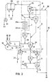
- FIG. 2 shows the system described above in a purely diagrammatic form, from which the configuration of heat exchangers 5, 6 and 9 with heat exchanger cyclones 12 to 18 can be seen in particular.
- the heat exchanger 6 is designed as a combustion air heater in the manner of a solid cooler with the heat exchanger cyclones 15, 16 and 17, while the heat exchanger 5 is designed as a solid fuel heater with the heat exchanger cyclones 13 and 14 and the solid preheater 9 with the cyclones 12 and 18.
- the function of these heat exchangers is assumed to be known.
- the number of cyclone stages shown is only an example. As is known per se, it can be determined in adaptation to different operating parameters of a heat exchanger unit at the discretion of the person skilled in the art.
- hot flue gas leaves the rotary kiln 1 in the temperature range above 1200 ° C. and is initially in the Heat exchanger cyclone 14 of the heat exchanger 5 initiated.
- a line leads 39 solids into the flow of flue gas 3.
- Gas and fine-grained solids give a suspension in which a spontaneous heat exchange between gas and solid takes place.
- This solid which contains, for example, rock powder and slag granulate, is conveyed from the heat exchanger 6 to the heat exchanger 9 with a conveying means 10 and is given up at the point 40.
- a first heat exchange with the flow of the flue gas takes place here in the solids preheater 9, the solids being preheated first.
- Preheated solid is then introduced with line 41 at point 42 into the solid fuel heater 5 and further heated therein.
- the further heated solid is fed via line 39 to the still unaocooled stream of flue gas 3 and heated to the final temperature.
- the heated solid 8 ' reaches the combustion air heater 6 via the line 43 hot solid gives off heat to the cold air 43 supplied with the fan 4 and thereby heats the air to combustion air temperature, for example between 300 and 800 ° C. or between, for example, 500 and 700 ° C. It can be seen from the examples shown in FIGS.
- solids such as lime or limestone, preferably in fine-grained form at 38 and occasionally also at 32, are introduced into the system and optionally mixed with granulated slag, which can also be introduced into the circuit of the heat exchanger solid.
- the positions of the task at 32 and 38 are only examples and can be varied according to professional judgment.
- used solids have to be deducted from them, for which at least one discharge is provided at 33, for example.
- the rotary kiln 1 has a preferably metering device for feeding the waste materials. Furthermore, the line 18 for hot combustion air 4 'opens into the rotary kiln 1 on its feed side.
- an end housing At the discharge end of the rotary tube furnace 1, an end housing, not shown, is arranged and formed with a slag discharge 20.
- Liquid slag 22 is, for example, thrown into the granulating device 21, granulated therein in a water bath, then conveyed out with a discharge device (not shown) and, as slag granules 23, is given in whole or in part to the transport device 10 'or discharged from the system.
- the granule device 21 has a water inlet 24.
- the flue gas 3 ' which has a low temperature after the removal of part of its heat content in the heat exchanger 5, can be introduced into a device 7 for waste heat utilization and can be used therein, for example, to generate steam.
- Flue gas emerging from the device 7 arrives in the solids preheater 9, where pollutants of the flue gas are chemically and adsorptively bound to the heat transfer solids at the same time as the heat transfer.
- Exhaust gas discharged from the solids preheater 9 with the line 27 is dedusted, for example, in a dedusting device 28, an electrical or fabric filter.
- the exhauster 30 draws the exhaust gas 44 out of the system and occasionally conveys it into a chimney, not shown.
- Fuel can be added to the flue gas with a fuel feed 34 or 34 'in the area of the heat exchanger 5, the gasification of which creates a reducing atmosphere. Nitrogen oxides generated in the furnace are reduced to elemental nitrogen and carbon is oxidized to form carbon monoxide. Excess carbon monoxide can then be combusted by introducing additional combustion air 35, for example into the waste heat recovery device 7 (FIG. 1) or 9 (FIG. 2). Dust 29 accumulating in the flue gas filter 28 can either be returned to the solid circuit or, depending on its pollutant content, can be removed from the system.
- the system As can be seen from the illustration and the description of the system according to the invention, it is compact, easy to operate and manageable consists essentially of known and proven individual elements. As a result of the optimization of the combustion conditions, the system works extremely economically and with absolute avoidance of the formation of toxic substances, especially dioxins, in the flue gas. As a result of the high combustion temperatures, the ash is melted, mineralized and primarily forms a leach-resistant slag that can be used as a building material, for example, or at least disposed of without damage. Finally, it can also be used as a heat transfer medium together with other solids. Heating the combustion air as well as used as filter material to bind pollutants in the flue gas.
Landscapes
- Engineering & Computer Science (AREA)
- Mechanical Engineering (AREA)
- General Engineering & Computer Science (AREA)
- Chemical & Material Sciences (AREA)
- Combustion & Propulsion (AREA)
- Health & Medical Sciences (AREA)
- Biomedical Technology (AREA)
- Environmental & Geological Engineering (AREA)
- Analytical Chemistry (AREA)
- General Chemical & Material Sciences (AREA)
- Oil, Petroleum & Natural Gas (AREA)
- Chemical Kinetics & Catalysis (AREA)
- Incineration Of Waste (AREA)
- Air Supply (AREA)
- Processing Of Solid Wastes (AREA)
- Gasification And Melting Of Waste (AREA)
Applications Claiming Priority (2)
| Application Number | Priority Date | Filing Date | Title |
|---|---|---|---|
| DE3444073 | 1984-12-03 | ||
| DE19843444073 DE3444073A1 (de) | 1984-12-03 | 1984-12-03 | Verfahren und anlage zum verbrennen von abfaellen wie haus-, industrie- und sondermuell |
Publications (2)
| Publication Number | Publication Date |
|---|---|
| EP0183961A2 true EP0183961A2 (fr) | 1986-06-11 |
| EP0183961A3 EP0183961A3 (fr) | 1988-06-08 |
Family
ID=6251785
Family Applications (1)
| Application Number | Title | Priority Date | Filing Date |
|---|---|---|---|
| EP85113433A Withdrawn EP0183961A3 (fr) | 1984-12-03 | 1985-10-23 | Procédé et appareil pour la combustion des déchets tels que les ordures ménagères, les déchets industriels ou les déchets spéciaux |
Country Status (5)
| Country | Link |
|---|---|
| US (1) | US4640203A (fr) |
| EP (1) | EP0183961A3 (fr) |
| JP (1) | JPS61184321A (fr) |
| DE (1) | DE3444073A1 (fr) |
| DK (1) | DK556585A (fr) |
Families Citing this family (25)
| Publication number | Priority date | Publication date | Assignee | Title |
|---|---|---|---|---|
| DE3605784A1 (de) * | 1986-02-22 | 1987-09-03 | Alexander Dipl Ing Grisar | Verfahren zur entsorgung von abfaellen, insbesondere hausmuell |
| DE3718595A1 (de) * | 1987-06-03 | 1988-12-15 | Nicolaus Dr Grubhofer | Verfahren zur beseitigung von fluessigen und/oder gasfoermigen abfallstoffen |
| US5376354A (en) * | 1987-10-16 | 1994-12-27 | Noell Abfall-Und Energietechnik Gmbh | Process for disposal of waste by combustion with oxygen |
| DK153888A (da) * | 1988-03-21 | 1989-09-22 | Fls Miljoe A S | Fremgangsmaade til forbraending af affald |
| DE3826894A1 (de) * | 1988-08-08 | 1990-02-15 | Harald Gebhard Boehler | Drehrohrofen mit sektionaler verbrennungsluftzufuhr |
| US4945839A (en) * | 1989-01-06 | 1990-08-07 | Collette Jerry R | Dual chamber volatilization system |
| US5265545A (en) * | 1989-04-12 | 1993-11-30 | Miltox Holdings Pte, Limited | Method and apparatus for waste treatment |
| DE4301814A1 (de) * | 1993-01-23 | 1994-07-28 | Steinmueller Gmbh L & C | Verfahren zum Verbrennen eines im wesentlichen aus Kunststoff bestehenden Abfalls, insbesondere PVC-Abfall |
| DE4337421C1 (de) * | 1993-11-03 | 1995-01-12 | Hans Dr Reimer | Mehrstufige Hochtemperaturverbrennung von Abfallstoffen mit Inertbestandteilen und Vorrichtung zur Durchführung dieses Verfahrens |
| DE19512785A1 (de) * | 1995-04-05 | 1996-10-17 | Siemens Ag | Verfahren zur thermischen Behandlung von Abfallstoffen |
| AUPN644895A0 (en) * | 1995-11-08 | 1995-11-30 | Miltox Holdings Pte Ltd | Method and apparatus for waste treatment |
| US5816795A (en) * | 1996-05-24 | 1998-10-06 | Cadence Environmental Energy, Inc. | Apparatus and method for providing supplemental fuel to a preheater/precalciner kiln |
| DE19706606A1 (de) * | 1997-02-20 | 1998-08-27 | Babcock Anlagen Gmbh | Verfahren zur Regelung der Temperatur in thermischen Abfallbehandlunganlagen und Abfallbehandlunganlage |
| HN1998000031A (es) * | 1997-06-11 | 1999-06-10 | Basf Ag | Metodo y aparatos mejorados para recuperar la energia de desechos mediante combustion de los mismos hornos industriales . |
| DE102009012668A1 (de) * | 2009-03-13 | 2010-09-16 | E.On Anlagenservice Gmbh | Verfahren und Anlage zur Verwertung von Biomasse |
| US10436525B2 (en) | 2016-05-12 | 2019-10-08 | Golden Renewable Energy, LLC | Cyclonic cooling system |
| CR20180575A (es) * | 2016-05-12 | 2019-04-25 | Golden Renewable Energy Llc | Sistema ciclonico de condensación y enfriamiento |
| US10961062B2 (en) | 2016-06-21 | 2021-03-30 | Golden Renewable Energy, LLC | Bag press feeder assembly |
| CA3028115A1 (fr) | 2016-06-21 | 2017-12-28 | Golden Renewable Energy, LLC | Separateur de residus de carbonisation et procede |
| US20170361268A1 (en) | 2016-06-21 | 2017-12-21 | Golden Renewable Energy | Char separator |
| CN109477010B (zh) | 2016-07-05 | 2021-07-23 | 戈登可再生能源有限公司 | 用于将废弃塑料转化成燃料的系统和工艺 |
| RU2691896C1 (ru) * | 2018-06-05 | 2019-06-18 | Федеральное государственное бюджетное образовательное учреждение высшего образования "Юго-Западный государственный университет" (ЮЗГУ) | Комплексный коррозионноустойчивый воздухоподогреватель |
| WO2021250304A1 (fr) * | 2020-06-08 | 2021-12-16 | Metso Outotec Finland Oy | Installation et procédé de traitement de matériau solide |
| RU2759629C1 (ru) * | 2021-04-28 | 2021-11-16 | Федеральное государственное бюджетное образовательное учреждение высшего образования «Юго-Западный государственный университет» (ЮЗГУ) (RU) | Санитарная насадка для дымовой трубы |
| KR20250149991A (ko) * | 2023-02-17 | 2025-10-17 | 파이퍼 팝 솔루션즈 게엠베하 | 환경적으로 해로운 및/또는 독성을 갖는 배기 가스를 처리하고 중화하기 위한 방법 및 장치 |
Family Cites Families (16)
| Publication number | Priority date | Publication date | Assignee | Title |
|---|---|---|---|---|
| US1101925A (en) * | 1913-08-23 | 1914-06-30 | John Brown Harris | Garbage-incinerator. |
| US2795213A (en) * | 1954-12-30 | 1957-06-11 | Air Preheater | Zoned air heater |
| FR1165502A (fr) * | 1955-12-19 | 1958-10-27 | Air Preheater | échangeur de chaleur dit à cailloux |
| CH411198A (de) * | 1964-07-08 | 1966-04-15 | Von Roll Ag | Verfahren zur Verbrennung von Abfallstoffen, insbesondere Müll, sowie Ofen zur Durchführung dieses Verfahrens |
| US3831668A (en) * | 1972-05-17 | 1974-08-27 | P Weissenburg | Tower type heat exchangers for heat interchange between gases heated to different temperatures |
| US4245571A (en) * | 1978-04-05 | 1981-01-20 | T R Systems, Inc. | Thermal reductor system and method for recovering valuable metals from waste |
| US4307773A (en) * | 1978-08-28 | 1981-12-29 | Smith Richard D | Fluid bed heat exchanger for contaminated gas |
| US4374540A (en) * | 1978-09-15 | 1983-02-22 | Consolidated Natural Gas Service Company, Inc. | Pneumatic transport and heat exchange systems |
| DK148368C (da) * | 1979-03-26 | 1985-11-04 | Henrik Have | Fremgangsmaade til udvinding af varme fra staldgoedning, spildevandsslam og andet vaadt affald ved forbraending |
| FR2452689A1 (fr) * | 1979-03-27 | 1980-10-24 | Saint Gobain | Procede de recuperation de chaleur sur des fumees |
| US4232614A (en) * | 1979-06-06 | 1980-11-11 | Dorr-Oliver Incorporated | Process of incineration with predrying of moist feed using hot inert particulates |
| DE3101244A1 (de) * | 1981-01-16 | 1982-08-26 | Von Roll AG, 4563 Gerlafingen | Kombinierter verbrennungs- und schmelzofen fuer feste, teigige und fluessige abfallstoffe |
| US4399756A (en) * | 1981-02-03 | 1983-08-23 | Lientz La Clede | Refuse burning process |
| US4349367A (en) * | 1981-03-31 | 1982-09-14 | Ppg Industries, Inc. | Method of recovering waste heat from furnace flue gases using a granular heat exchange means |
| DE3236753C1 (de) * | 1982-10-05 | 1984-03-22 | L. & C. Steinmüller GmbH, 5270 Gummersbach | Asche- und Schlackeaustragvorrichtung |
| EP0126619B1 (fr) * | 1983-05-17 | 1990-09-12 | PEDCo INC. | Procédé et dispositif de combustion des matériaux |
-
1984
- 1984-12-03 DE DE19843444073 patent/DE3444073A1/de not_active Withdrawn
-
1985
- 1985-10-23 EP EP85113433A patent/EP0183961A3/fr not_active Withdrawn
- 1985-11-27 US US06/802,246 patent/US4640203A/en not_active Expired - Fee Related
- 1985-12-02 DK DK556585A patent/DK556585A/da not_active Application Discontinuation
- 1985-12-03 JP JP60270858A patent/JPS61184321A/ja active Pending
Also Published As
| Publication number | Publication date |
|---|---|
| US4640203A (en) | 1987-02-03 |
| DK556585A (da) | 1986-06-04 |
| JPS61184321A (ja) | 1986-08-18 |
| EP0183961A3 (fr) | 1988-06-08 |
| DK556585D0 (da) | 1985-12-02 |
| DE3444073A1 (de) | 1986-06-05 |
Similar Documents
| Publication | Publication Date | Title |
|---|---|---|
| EP0183961A2 (fr) | Procédé et appareil pour la combustion des déchets tels que les ordures ménagères, les déchets industriels ou les déchets spéciaux | |
| EP0162215B1 (fr) | Procédé pour la mise au rebut de déchets combustibles | |
| DE102008054038B3 (de) | Verfahren und Vorrichtung zur Reduzierung von Schadstoffemissionen in Verbrennungsanlagen | |
| EP0459194B1 (fr) | Procédé d'élimination thermique de boues de décantation | |
| EP0141932A2 (fr) | Procédé et installation pour l'élimination sans substance nuisible de matières nocives et résiduaires de pouvoir calorifique inférieur, en particulier des déchets, par combustion | |
| EP1334954A1 (fr) | Installation de préparation de clinker de ciment | |
| EP0465479B1 (fr) | Procede de transformation de boues de curage | |
| DE69006498T2 (de) | Schlammverbrennung in einem einstufen-vergasungsbrenner mit gasreinigung und anschliessender nachverbrennung sowie wärmerückgewinnung. | |
| DE3635068C2 (fr) | ||
| WO1987001692A2 (fr) | Utilisation de dechets a pouvoir calorifique pour la production de ciment | |
| DE3718669A1 (de) | Verfahren zur aufarbeitung von kontaminierten mineralstoffen | |
| EP0302910B1 (fr) | Combustion de charbon avec un foyer a lit fluidise | |
| DE2648789A1 (de) | Verfahren zum thermischen calcinieren von mineralien | |
| DE3527615A1 (de) | Verfahren und anlage zur entsorgung von chlorhaltigen abfaellen, insbesondere von haus- und kommunalmuell | |
| JPS60221349A (ja) | 可燃性廃物の処理法 | |
| DE3520447A1 (de) | Verfahren und anlage zur thermischen behandlung von feinkoernigem gut wie zementrohmehl, unter verwendung von brennstoffhaltigen abfaellen und/oder minderwertigen brennstoffen | |
| DE2726157B2 (de) | Brennofenanlage für feste Güter | |
| DE3729210A1 (de) | Verfahren zur thermischen entsorgung von abfallstoffen | |
| DE3537595A1 (de) | Verfahren und anlage zur verwertung von feuchten abfaellen, insbesondere klaerschlamm | |
| DE69004258T2 (de) | Behandlung von betriebsgasen mit halogenhaltigen verbindungen. | |
| EP0204888A1 (fr) | Procédé pour la combustion des déchets, particulièrement des ordures et des boues | |
| EP0303963A2 (fr) | Procédé et dispositif pour la calcination de pierre à chaux | |
| EP1918015B1 (fr) | Equilibrage des gaz de fumées dans des installations de combustion de déchets | |
| CH688871A5 (de) | Verfahren zur thermischen Energiegewinnung aus Abfallmaterial, insbesondere Muell. | |
| DE19938034C2 (de) | Verfahren zur Aufarbeitung von mit Schadstoffen belastetem Gut |
Legal Events
| Date | Code | Title | Description |
|---|---|---|---|
| PUAI | Public reference made under article 153(3) epc to a published international application that has entered the european phase |
Free format text: ORIGINAL CODE: 0009012 |
|
| AK | Designated contracting states |
Kind code of ref document: A2 Designated state(s): AT BE CH DE FR GB IT LI LU NL |
|
| RAP1 | Party data changed (applicant data changed or rights of an application transferred) |
Owner name: GRISAR, ALEXANDER Owner name: KLOECKNER-HUMBOLDT-DEUTZ AKTIENGESELLSCHAFT |
|
| RAP1 | Party data changed (applicant data changed or rights of an application transferred) |
Owner name: KLOECKNER-HUMBOLDT-DEUTZ AKTIENGESELLSCHAFT Owner name: GRISAR, ALEXANDER |
|
| PUAL | Search report despatched |
Free format text: ORIGINAL CODE: 0009013 |
|
| AK | Designated contracting states |
Kind code of ref document: A3 Designated state(s): AT BE CH DE FR GB IT LI LU NL |
|
| STAA | Information on the status of an ep patent application or granted ep patent |
Free format text: STATUS: THE APPLICATION IS DEEMED TO BE WITHDRAWN |
|
| 18D | Application deemed to be withdrawn |
Effective date: 19880503 |
|
| RIN1 | Information on inventor provided before grant (corrected) |
Inventor name: HARTMANN, ROLF Inventor name: GRISAR, ALEXANDER Inventor name: WOLTER, ALBRECHT, DR. Inventor name: HERCHENBACH, HORST |