EP0183972A1 - Equipement de pièce à main dentaire - Google Patents
Equipement de pièce à main dentaire Download PDFInfo
- Publication number
- EP0183972A1 EP0183972A1 EP85113623A EP85113623A EP0183972A1 EP 0183972 A1 EP0183972 A1 EP 0183972A1 EP 85113623 A EP85113623 A EP 85113623A EP 85113623 A EP85113623 A EP 85113623A EP 0183972 A1 EP0183972 A1 EP 0183972A1
- Authority
- EP
- European Patent Office
- Prior art keywords
- sleeve
- handpiece
- motor
- arrangement according
- cartridge
- Prior art date
- Legal status (The legal status is an assumption and is not a legal conclusion. Google has not performed a legal analysis and makes no representation as to the accuracy of the status listed.)
- Granted
Links
- 230000008878 coupling Effects 0.000 claims abstract description 33
- 238000010168 coupling process Methods 0.000 claims abstract description 33
- 238000005859 coupling reaction Methods 0.000 claims abstract description 33
- XLYOFNOQVPJJNP-UHFFFAOYSA-N water Substances O XLYOFNOQVPJJNP-UHFFFAOYSA-N 0.000 claims abstract description 19
- 238000001816 cooling Methods 0.000 claims description 7
- 239000002826 coolant Substances 0.000 claims description 3
- 0 CC1(*)C2=C=C2CC2*=*C12 Chemical compound CC1(*)C2=C=C2CC2*=*C12 0.000 description 2
- OKTJSMMVPCPJKN-UHFFFAOYSA-N Carbon Chemical compound [C] OKTJSMMVPCPJKN-UHFFFAOYSA-N 0.000 description 1
- 229910052799 carbon Inorganic materials 0.000 description 1
- 230000001276 controlling effect Effects 0.000 description 1
- 238000011161 development Methods 0.000 description 1
- 230000018109 developmental process Effects 0.000 description 1
- 238000005516 engineering process Methods 0.000 description 1
- 230000013011 mating Effects 0.000 description 1
- 230000001105 regulatory effect Effects 0.000 description 1
- 230000000717 retained effect Effects 0.000 description 1
- 239000007921 spray Substances 0.000 description 1
- 230000001954 sterilising effect Effects 0.000 description 1
- 238000004659 sterilization and disinfection Methods 0.000 description 1
Images


Classifications
-
- A—HUMAN NECESSITIES
- A61—MEDICAL OR VETERINARY SCIENCE; HYGIENE
- A61C—DENTISTRY; APPARATUS OR METHODS FOR ORAL OR DENTAL HYGIENE
- A61C1/00—Dental machines for boring or cutting ; General features of dental machines or apparatus, e.g. hand-piece design
- A61C1/02—Dental machines for boring or cutting ; General features of dental machines or apparatus, e.g. hand-piece design characterised by the drive of the dental tools
- A61C1/06—Dental machines for boring or cutting ; General features of dental machines or apparatus, e.g. hand-piece design characterised by the drive of the dental tools with electric drive
Definitions
- the invention relates to a dental handpiece arrangement with a drive motor, to the shaft of which the drive shaft section of a handpiece part containing a grip sleeve with a head housing can be coupled.
- a handpiece arrangement has also become established in recent years, in which the grip sleeve normally remains on the drive part and only relatively short treatment heads containing the head housing are easily detachably coupled to the drive part.
- the grip sleeve itself is removed from the drive only for sterilization purposes together with a sleeve which overlaps the drive part, which contains the media guide.
- Handle sleeve and treatment head are freely rotatable with respect to the drive part, but not the sleeve which overlaps the motor and which can be pulled off from the drive part together with the handle sleeve (US Pat. No. 4,251,212).
- the media is also guided within the drive section, and the media is transferred via an appropriately trained guide pin.
- the invention specified in claim 1 is therefore an object of the invention to provide a handpiece arrangement with which the prerequisite is created that one and the same drive motor for the use of conventional handpieces and contra-angle handpieces as well as for the use of already known and possibly others , cross-motor handpiece parts can be provided, both light-guiding handpieces and those without light should be coupled to the drive motor.
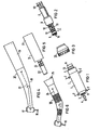
- FIG. 1 shows the basic element of the handpiece arrangement according to the invention, the motor cartridge.
- the motor cartridge designated I in the illustration, has essentially cylindrical outer surfaces 1, which form two spaced-apart sliding bearing surfaces for the handpiece parts which can be placed on the motor cartridge at the points provided with the arrows 2.
- the motor cartridge essentially only accommodates the motor-specific parts, that is to say the rotor, stator, bearings, brushes and brush holder.
- the one end of the cartridge protruding end of the motor shaft 3 contains a driver 4, with which the motor shaft is coupled to the corresponding drive shaft section of the handpiece part in a known manner by attaching the handpiece parts, which will be explained in more detail later.
- 5 denotes an annular groove arranged on a further shoulder of the motor cartridge, which is part of a latching device by means of which the handpiece parts to be attached can be axially latched relative to the drive cartridge while maintaining their rotatability.
- the other end face of the drive cartridge forms an extension 6, the outer diameter of which is significantly smaller than that of the cylindrical lateral surfaces 1 which form the two sliding bearings.
- the approach 6 is, as can be seen from the sectional view according to FIG. 7, part of a sleeve screwed onto the motor cartridge.
- the pin 7 of a connection part shown in FIG. 2, designated II can be partially inserted into the opening of the sleeve-shaped extension 6 and can be firmly (non-rotatably) connected to the motor cartridge by means of a screw connection 8.
- the leads which are brought up in a supply hose 9 and are designated by 10, for electrical energy on the one hand and air and water on the other hand. Air and water open out in a known manner at radial openings 11, 12 arranged on the circumference of the pin and sealed against one another by O-rings (not designated in any more detail).
- the latter consists of a contact socket arranged centrally in the pin 7 and a contact spring arranged concentrically thereto.
- the pair of slip rings 13 is used to supply electrical energy to a lighting device, which will be explained in more detail later, the pair of contacts 14 to supply the necessary voltage to the motor.
- FIG. 3 shows a coupling body designated III, which, before the connection fitting II shown in FIG. 2 is screwed to the motor cartridge, is axially attached to the extension 6 and axially fixed by means of an O-ring 15 (FIG. 1). Details of the coupling body can be seen from the sectional view in FIG. 7.
- the handpiece according to FIG. 4 is a handpiece part in which a head housing 17, which accommodates the tool 16 to be driven, together with a grip sleeve 18, which extends to the motor-side end, and a further sleeve 19, which overlaps the motor cartridge and accommodates the counter bearing surfaces in FIG. 2 .
- the motor-side end of the drive shaft sections of the handpiece part IV, generally designated 20 is in engagement with the motor shaft 3.
- the adapter V according to FIG. 5 contains a sleeve-shaped section 21 and a guide pin 22, on which the media air and water are sealed in a known manner at radially opening openings 23, sealed against one another by unspecified 0-rings 24, for further acceptance in one on the Pins 22 attachable hand and angle piece, as shown in Figure 6, are offered.
- the pin 22 is dimensioned such that standard handpieces and contra-angle handpieces standardized in accordance with ISO, as shown in simplified form in FIG. 6, can be attached to it.
- the drive shaft sections 24 are also connected to the motor shaft 3.
- 25 also designates a nose protruding from the front of the handpiece VI, which, as will be explained in more detail later, is intended to trigger a switching operation. Further details of the adapter V can be seen in FIGS. 11 to 14.
- FIG. 7 shows the motor cartridge I with the coupling body III attached in a longitudinal section. From the illustration it can be seen that the motor housing 26 in the WE - sentlichen only the motor-specific parts, that the rotor 27, bearings 28, stator 29, brush and holder 30, etc., however, no coolant lines and light guide contains.
- the lug 6 carrying the coupling body III is the one section of a sleeve which is stepped in outer diameter, the other section of which is screwed to the motor housing 26.
- the inside diameter of the stepped part of the sleeve is dimensioned such that the guide pin 7 of the connecting part II can be inserted and connected there to the motor cartridge I via the screw connection 8.
- the brush holder 30 is e.g. accessible for the exchange of the carbon brushes.
- a mating contact pair 32 is provided for the contact pair 14 on the pin 7 (FIG. 2), consisting of a centrally arranged pin and a contact ring which is arranged concentrically insulated from it.
- the coupling body III rotatably mounted on the extension 6 is the carrier of an electric incandescent lamp 35 with associated lamp holder 36 and a switching device designated 37 for switching the lamp on and off when one or the other handpiece part IV or V is plugged onto the motor cartridge I.
- the coupling body III also contains the line channels necessary for air and water and a flow control device for controlling the flow of one or the other medium.
- the lamp or lamp holder and the connection sockets for water and air designated 38 and 39 (FIG. 8) are combined in a holder part 40 to a relatively narrowly limited angular range ( ⁇ ) of approximately 60 ° to 70 ° of the circumference and end at the end (FIG.
- the incandescent lamp 35 is arranged obliquely to the motor axis. This can be advantageous for reasons of space; however, this arrangement is not absolutely necessary; rather, the lamp can also be arranged horizontally, that is to say with a longitudinal axis running parallel to the motor axis, in the holding part 40.
- connection sockets 38, 39 for water and air are arranged symmetrically with respect to the central lamp 35.
- FIG. 9 shows a section along the line IX / IX in FIG. 8, the media guidance within the coupling body III is shown, using the example of the water guidance.
- the water flows through a channel 42 taken from the opening 12 in the pin 7 (FIG. 2) and guided by means of a flexible hose section 43 arranged in the holding part 40 to an end part 44 containing the bush 38.
- the socket or socket and end part 44 are advantageously arranged interchangeably in part 40.
- the air duct is designed analogously.
- a control device for determining the flow rate is additionally provided for the water flow.
- This regulating device contains a ball 45, which is adjusted with the aid of an adjusting ring 47 having an eccentrically arranged positioning surface 46 when it is rotated in order to pinch the hose section 43.
- the adjusting ring 47 is formed in two parts and consists of a first ring 47a containing the positioning surface 46 and a second ring 47b covering the incandescent lamp 35.
- the part 40 contains axially projecting positioning and driving parts 49 with mutually parallel surfaces 48 (FIG. 8), which come into engagement with counter surfaces 68 of counter members 69 which are correspondingly arranged on the handpiece parts (IV / V) to be coupled, when these handpiece parts are placed on the motor cartridge and Connect handpiece part and coupling body for a common rotation.
- FIG. 10 shows a cross section along the line X / X in FIG.
- resilient contact tabs 50, 51 are arranged, one end of which forms the lamp holder 36 and the other end of which forms one end, designated 52, on the one slip ring of the contact pair 13 (FIG. 2) of the pin 7 and the other, designated 53 with a spring-loaded (spring 54 in Figure 7) switching cam (item 37 in Figure 7) cooperates.
- the switching cam 27 is actuated axially, the contact section denoted by 56 is released, as a result of which contact is made with the second slip ring of the slip ring pair 13 and the lamp 35 is switched on.
- the structure of the handpiece part which can be placed on the motor cartridge is explained using FIGS. 11 to 14 using the example of the adapter V.
- the measures provided for this special handpiece part in relation to the guidance of the media air, water and light and for switching on the lamp also apply accordingly to a handpiece part which, as shown in FIG. 4, is designed.
- the sleeve-shaped section 21 which overlaps the motor cartridge I consists of a thin outer sleeve 60 which forms the outer covering and an insert part 61, the inner contour of which corresponds to the motor cartridge I and in particular has the counter surfaces which are necessary for rotation and correspond to the bearing points 2.
- the insert 61 contains on its periphery recesses 62 which form an annular space with the outer sleeve 60, in which on the one hand pipes 63 and 64 for carrying air and water and on the other hand a light guide 65 and a switch rod 66 are guided or held.
- the parts 63 to 66 are inserted in the annular space so that the intermediate space for the passage of cooling air can be used to cool the engine.
- the cooling air first flows through the coupling body III, the air duct being designed so that the lamp 35 is cooled by the air flowing past, then occurs from the in Figure 8 with 57 designated exit openings coming into the sleeve 21 at the points indicated by arrows in Figures 11 and 13, then flows through the adapter between the outer sleeve 60 and the insert part 61, occurs in the area of the ring groove 5 the motor cartridge interacting ball catch 67 from the adapter and re-enters the interior of the motor via the channels 33 when the adapter is plugged onto the motor cartridge.
- the adapter has an essentially U-shaped part 69 with mutually parallel surfaces 68 which match the positioning surfaces shown in FIG and which, when the adapter is plugged in, cause the adapter to be centered and positioned relative to the coupling body, so that in the coupled state the light guide end 65a is correspondingly opposite the incandescent lamp 35 and the ends 63a, 64a of the two media-carrying channels 63 and 64 into the corresponding connection sockets 38, 39 of the clutch body III engage.
- the one end of the shift linkage 66 designated 66a, bears against the contact surface of the switching device 37, designated 58 in FIG. 7.
- the adapter V has a circular cross-section on the end face facing the pin 22, centered on the motor axis, whereas on the opposite end in the area of the media transfer, it has a cross-section that is eccentric to the motor axis.
- the sleeve-shaped end part 19 is constructed, i.e. here too, the lines for light, air and water are provided in the manner described so that they match the connecting elements in the coupling body III.
- the handpiece arrangement according to the invention is not limited to the use of a drive cartridge equipped with an electric motor; rather, it can also be used for a drive cartridge with an air motor.
Landscapes
- Health & Medical Sciences (AREA)
- Oral & Maxillofacial Surgery (AREA)
- Dentistry (AREA)
- Epidemiology (AREA)
- Life Sciences & Earth Sciences (AREA)
- Animal Behavior & Ethology (AREA)
- General Health & Medical Sciences (AREA)
- Public Health (AREA)
- Veterinary Medicine (AREA)
- Dental Tools And Instruments Or Auxiliary Dental Instruments (AREA)
Priority Applications (1)
| Application Number | Priority Date | Filing Date | Title |
|---|---|---|---|
| AT85113623T ATE39834T1 (de) | 1984-11-09 | 1985-10-25 | Zahnaerztliche handstueckanordnung. |
Applications Claiming Priority (2)
| Application Number | Priority Date | Filing Date | Title |
|---|---|---|---|
| DE3441024 | 1984-11-09 | ||
| DE3441024 | 1984-11-09 |
Publications (2)
| Publication Number | Publication Date |
|---|---|
| EP0183972A1 true EP0183972A1 (fr) | 1986-06-11 |
| EP0183972B1 EP0183972B1 (fr) | 1989-01-11 |
Family
ID=6249940
Family Applications (1)
| Application Number | Title | Priority Date | Filing Date |
|---|---|---|---|
| EP85113623A Expired EP0183972B1 (fr) | 1984-11-09 | 1985-10-25 | Equipement de pièce à main dentaire |
Country Status (6)
| Country | Link |
|---|---|
| US (1) | US4681540A (fr) |
| EP (1) | EP0183972B1 (fr) |
| JP (1) | JPS61115552A (fr) |
| AT (1) | ATE39834T1 (fr) |
| CS (1) | CS807585A3 (fr) |
| DE (1) | DE3567369D1 (fr) |
Cited By (4)
| Publication number | Priority date | Publication date | Assignee | Title |
|---|---|---|---|---|
| EP0185290B1 (fr) * | 1984-12-21 | 1989-05-31 | Siemens Aktiengesellschaft | Pièce à main dentaire avec éclairage |
| DE4138681C1 (fr) * | 1991-11-25 | 1993-06-24 | Kaltenbach & Voigt Gmbh & Co, 7950 Biberach, De | |
| DE4143406A1 (de) * | 1991-11-25 | 1993-07-01 | Kaltenbach & Voigt | Aertzliches, motorbetriebenes behandlungsinstrument mit einem aus mindestens zwei teilen bestehenden handstueck |
| EP0812578A1 (fr) * | 1996-06-12 | 1997-12-17 | Micro Mega International Manufactures Sa | Ensemble moteur-pièce à main contre-angle avec un moteur pas-à-pas |
Families Citing this family (31)
| Publication number | Priority date | Publication date | Assignee | Title |
|---|---|---|---|---|
| DE8717222U1 (de) * | 1987-02-26 | 1989-04-13 | Siemens AG, 1000 Berlin und 8000 München | Zahnärztliches Handstück |
| JPS63270045A (ja) * | 1987-04-30 | 1988-11-08 | Yoshida Dental Mfg Co Ltd | 駆動モ−タを内蔵した治療器具 |
| JPH0626249Y2 (ja) * | 1988-05-23 | 1994-07-20 | 株式会社長田中央研究所 | 歯科治療用ホース端の接続構造 |
| DE9115186U1 (de) * | 1991-12-06 | 1992-02-06 | IMTEC Innovative Medizintechnik Gesellschaft m.b.H., Hallein | Zahnärztliches Handstück |
| US5639236A (en) * | 1995-08-11 | 1997-06-17 | Martin; Howard | Root canal dental handpiece |
| DE19702996C1 (de) * | 1997-01-28 | 1998-05-07 | Siemens Ag | Einrichtung zur Erkennung der Entnahme eines an einen Versorgungsschlauch angeschlossenen zahnärztlichen Handstückes aus einer Ablagevorrichtung |
| JPH1189855A (ja) * | 1997-09-24 | 1999-04-06 | Nakanishi:Kk | 歯科用ハンドピース |
| US6149430A (en) * | 1998-02-20 | 2000-11-21 | Ora Innovations, Inc. | Integrally molded dental appliance and process for its manufacture |
| US20070059664A1 (en) * | 2000-09-14 | 2007-03-15 | Novak Eugene J | Bearing for dental handpiece |
| US20020168612A1 (en) * | 2000-09-14 | 2002-11-14 | Novak Eugene J. | Bearing for dental handpiece |
| US20060234186A1 (en) * | 2000-09-14 | 2006-10-19 | Novak Eugene J | Bearing for dental handpiece |
| CA2431109C (fr) * | 2000-12-18 | 2012-02-21 | Dentsply International Inc. | Composants ameliores de piece a main de dentisterie |
| US20020124443A1 (en) * | 2000-12-18 | 2002-09-12 | Dentsply Research & Development Corp. | Metal-to-metal connections |
| ITBO20010051A1 (it) * | 2001-01-31 | 2002-07-31 | Castellini Spa | Manipolo odontoiatrico, in particolare per riuniti dentali |
| US20070031786A1 (en) * | 2002-02-25 | 2007-02-08 | Heil Donald J | Dental handpiece |
| US20070117064A1 (en) * | 2002-02-27 | 2007-05-24 | Novak Eugene J | Dental handpiece with improved grease retention |
| CA2477167A1 (fr) * | 2002-02-27 | 2003-09-04 | Dentsply International Inc. | Piece a main dentaire comprenant une retenue de graisse |
| CA2480810A1 (fr) * | 2002-03-28 | 2003-10-09 | Dentsply International Inc. | Technique d'equilibrage d'elements rotatifs de turbine sur un instrument dentaire |
| US20060191336A1 (en) * | 2002-03-28 | 2006-08-31 | Dentsply Research & Development Corp. | Method and apparatus for balancing the rotating elements of a dental handpiece |
| ATE522183T1 (de) * | 2007-03-12 | 2011-09-15 | W & H Dentalwerk Buermoos Gmbh | Mit einem elektromotor betreibbares laborhandstück |
| US20100035205A1 (en) * | 2008-08-09 | 2010-02-11 | Daniel Wang | Non-90-Degree Ergonomically-Shaped Dental Prophylaxis Angle with a Straight Driving Shaft |
| US9318934B2 (en) * | 2009-03-20 | 2016-04-19 | Kaltenbach & Voigt Gmbh | Electric motor arrangement for a medical, especially dental, tool holder |
| USD645964S1 (en) * | 2009-11-25 | 2011-09-27 | Nakanishi Inc. | Motor for dental handpiece |
| DE102010028245A1 (de) * | 2010-04-27 | 2011-10-27 | Kaltenbach & Voigt Gmbh | Elektromotoranordnung für ein medizinisches, insbesondere ein dentales Handstück, sowie Dentalinstrumententeil |
| JP5767021B2 (ja) * | 2011-05-26 | 2015-08-19 | 株式会社ナカニシ | 歯科用ハンドピースの流体回路接続構造 |
| US10178997B2 (en) | 2014-09-24 | 2019-01-15 | Gyrus Acmi, Inc. | High-speed powered hand tool with improved motor cooling |
| US10368969B2 (en) | 2017-04-21 | 2019-08-06 | Xlr8 Holdings, Llc | Hand-held device utilizing an activation mechanism which spans the circumference of said device |
| DE102017211769A1 (de) * | 2017-07-10 | 2019-01-10 | Sirona Dental Systems Gmbh | Zahnärztliches Handstück |
| JP1641370S (fr) * | 2019-03-01 | 2019-09-17 | ||
| JP1641369S (fr) * | 2019-03-01 | 2019-09-17 | ||
| DE102023106239A1 (de) * | 2023-03-13 | 2024-09-19 | Andreas Neff | Vorrichtung zum lösbaren Verbinden mit einem medizinischen Handinstrument, vorzugsweise einem zahnmedizinischen Handinstrument, sowie Leuchtmittel zur Verwendung in einer solchen Vorrichtung |
Citations (4)
| Publication number | Priority date | Publication date | Assignee | Title |
|---|---|---|---|---|
| DE1250053B (fr) * | 1964-10-10 | 1967-09-14 | ||
| FR2280355A1 (fr) * | 1974-07-31 | 1976-02-27 | Siemens Ag | Moteur electrique miniature pour l'entrainement de pieces a main de dentisterie |
| FR2345135A1 (fr) * | 1976-03-26 | 1977-10-21 | Siemens Ag | Moteur d'entrainement pour une piece a main, eventuellement coudee, de dentisterie |
| DE2659060B1 (de) * | 1976-12-27 | 1978-07-06 | Kaltenbach & Voigt | Kleinstmotor mit innenliegender Kuehlmittelleitung |
Family Cites Families (6)
| Publication number | Priority date | Publication date | Assignee | Title |
|---|---|---|---|---|
| DE1905624C3 (de) * | 1969-02-05 | 1978-07-13 | Siemens Ag, 1000 Berlin Und 8000 Muenchen | Zahnärztliches Bohrhandstück |
| DE2431472C2 (de) * | 1974-07-01 | 1985-07-25 | Siemens AG, 1000 Berlin und 8000 München | Zahnärztliches Handstück mit Elektrokleinstmotor |
| US4184256A (en) * | 1977-12-12 | 1980-01-22 | Kaltenbach & Voigt Gmbh & Co. | Miniature motor having an internal coolant line |
| DE2855874A1 (de) * | 1978-12-22 | 1980-07-10 | Siemens Ag | Zahnaerztliche handstueckanordnung |
| US4271596A (en) * | 1979-11-06 | 1981-06-09 | Ganis G Robert | Instrument and method for determining map coordinates |
| DE3132995A1 (de) * | 1981-08-20 | 1983-03-03 | Siemens AG, 1000 Berlin und 8000 München | Zahnaerztliche handstueckanordnung |
-
1985
- 1985-10-17 US US06/788,727 patent/US4681540A/en not_active Expired - Fee Related
- 1985-10-25 DE DE8585113623T patent/DE3567369D1/de not_active Expired
- 1985-10-25 EP EP85113623A patent/EP0183972B1/fr not_active Expired
- 1985-10-25 AT AT85113623T patent/ATE39834T1/de not_active IP Right Cessation
- 1985-11-06 JP JP60248677A patent/JPS61115552A/ja active Granted
- 1985-11-08 CS CS858075A patent/CS807585A3/cs unknown
Patent Citations (4)
| Publication number | Priority date | Publication date | Assignee | Title |
|---|---|---|---|---|
| DE1250053B (fr) * | 1964-10-10 | 1967-09-14 | ||
| FR2280355A1 (fr) * | 1974-07-31 | 1976-02-27 | Siemens Ag | Moteur electrique miniature pour l'entrainement de pieces a main de dentisterie |
| FR2345135A1 (fr) * | 1976-03-26 | 1977-10-21 | Siemens Ag | Moteur d'entrainement pour une piece a main, eventuellement coudee, de dentisterie |
| DE2659060B1 (de) * | 1976-12-27 | 1978-07-06 | Kaltenbach & Voigt | Kleinstmotor mit innenliegender Kuehlmittelleitung |
Cited By (6)
| Publication number | Priority date | Publication date | Assignee | Title |
|---|---|---|---|---|
| EP0185290B1 (fr) * | 1984-12-21 | 1989-05-31 | Siemens Aktiengesellschaft | Pièce à main dentaire avec éclairage |
| DE4138681C1 (fr) * | 1991-11-25 | 1993-06-24 | Kaltenbach & Voigt Gmbh & Co, 7950 Biberach, De | |
| DE4143406A1 (de) * | 1991-11-25 | 1993-07-01 | Kaltenbach & Voigt | Aertzliches, motorbetriebenes behandlungsinstrument mit einem aus mindestens zwei teilen bestehenden handstueck |
| EP0544273A3 (fr) * | 1991-11-25 | 1994-03-23 | Kaltenbach & Voigt | |
| EP0812578A1 (fr) * | 1996-06-12 | 1997-12-17 | Micro Mega International Manufactures Sa | Ensemble moteur-pièce à main contre-angle avec un moteur pas-à-pas |
| FR2749751A1 (fr) * | 1996-06-12 | 1997-12-19 | Micro Mega Int Mfg Sa | Ensemble moteur-piece a main a contre-angle avec un moteur pas-a-pas |
Also Published As
| Publication number | Publication date |
|---|---|
| CS807585A3 (en) | 1992-06-17 |
| ATE39834T1 (de) | 1989-01-15 |
| EP0183972B1 (fr) | 1989-01-11 |
| JPH0376141B2 (fr) | 1991-12-04 |
| DE3567369D1 (en) | 1989-02-16 |
| US4681540A (en) | 1987-07-21 |
| JPS61115552A (ja) | 1986-06-03 |
Similar Documents
| Publication | Publication Date | Title |
|---|---|---|
| EP0183972B1 (fr) | Equipement de pièce à main dentaire | |
| EP0185290B1 (fr) | Pièce à main dentaire avec éclairage | |
| EP0369043B2 (fr) | Pièce à main dentaire pourvue de moyens qui permettent une connexion compatible avec divers types d'accouplement rotatif | |
| DE3215255C2 (de) | Zahnärztliche Handstückeinrichtung | |
| DE3215207C2 (fr) | ||
| DE3734861C2 (fr) | ||
| DE3072209T2 (de) | Zahnärztliches Instrument mit Handstück. | |
| DE3104239C2 (de) | Zahnärztliches Handstück | |
| DE2549177C3 (de) | Kupplungsvorrichtung für zahnärztliche Handstücke | |
| DE2431472C2 (de) | Zahnärztliches Handstück mit Elektrokleinstmotor | |
| DE2558064C3 (de) | Zahnärztliche Handstückanordnung | |
| EP0012873B1 (fr) | Assemblage d'instrument à main dentaire | |
| DE3328605C2 (de) | Handstück zur Zahnsteinentfernung | |
| DE3121287A1 (de) | "lichtleitfaseroptik fuer laser" | |
| DE3332627C2 (fr) | ||
| DE3537807A1 (de) | Dental-bohrhandstueck | |
| EP1900337B1 (fr) | Pièce à main médicale ou dentaire dotée d'une section arrière et avant | |
| DE3530461A1 (de) | Zahnaerztliches handstueck | |
| DE2207240A1 (de) | Absperr- und einstellventil fuer zahnaerztliche handstuecke | |
| DE3431052A1 (de) | Kupplungsvorrichtung fuer zahnaerztliche handstuecke | |
| DE19613681C2 (de) | Dentales Handstück | |
| CH623739A5 (en) | Drive device having an extremely small motor, a coolant line, a connection piece and a coupling piece for a handpiece-like instrument | |
| DE2542826C3 (de) | Vorrichtung zur Versorgung eines mit einem Antrieb für ein zahnärztliches Werkzeug versehenen Handstückes mit Kühlmittel | |
| EP0286790B1 (fr) | Arrangement de pièce à main dentaire avec moyens pour la transmission de la lumière | |
| EP2774571A1 (fr) | Convertisseur dynamoélectrique et dispositif médical, en particulier dentaire, doté d'un convertisseur dynamoélectrique |
Legal Events
| Date | Code | Title | Description |
|---|---|---|---|
| PUAI | Public reference made under article 153(3) epc to a published international application that has entered the european phase |
Free format text: ORIGINAL CODE: 0009012 |
|
| AK | Designated contracting states |
Kind code of ref document: A1 Designated state(s): AT CH DE FR GB IT LI SE |
|
| 17P | Request for examination filed |
Effective date: 19860707 |
|
| 17Q | First examination report despatched |
Effective date: 19870930 |
|
| GRAA | (expected) grant |
Free format text: ORIGINAL CODE: 0009210 |
|
| AK | Designated contracting states |
Kind code of ref document: B1 Designated state(s): AT CH DE FR GB IT LI SE |
|
| REF | Corresponds to: |
Ref document number: 39834 Country of ref document: AT Date of ref document: 19890115 Kind code of ref document: T |
|
| REF | Corresponds to: |
Ref document number: 3567369 Country of ref document: DE Date of ref document: 19890216 |
|
| ET | Fr: translation filed | ||
| ITF | It: translation for a ep patent filed | ||
| GBT | Gb: translation of ep patent filed (gb section 77(6)(a)/1977) | ||
| PLBE | No opposition filed within time limit |
Free format text: ORIGINAL CODE: 0009261 |
|
| STAA | Information on the status of an ep patent application or granted ep patent |
Free format text: STATUS: NO OPPOSITION FILED WITHIN TIME LIMIT |
|
| 26N | No opposition filed | ||
| ITTA | It: last paid annual fee | ||
| PGFP | Annual fee paid to national office [announced via postgrant information from national office to epo] |
Ref country code: GB Payment date: 19930913 Year of fee payment: 9 |
|
| PG25 | Lapsed in a contracting state [announced via postgrant information from national office to epo] |
Ref country code: GB Effective date: 19941025 |
|
| EAL | Se: european patent in force in sweden |
Ref document number: 85113623.4 |
|
| GBPC | Gb: european patent ceased through non-payment of renewal fee |
Effective date: 19941025 |
|
| PGFP | Annual fee paid to national office [announced via postgrant information from national office to epo] |
Ref country code: SE Payment date: 19971029 Year of fee payment: 13 |
|
| REG | Reference to a national code |
Ref country code: CH Ref legal event code: PUE Owner name: SIEMENS AKTIENGESELLSCHAFT BERLIN UND MUENCHEN -DA |
|
| PG25 | Lapsed in a contracting state [announced via postgrant information from national office to epo] |
Ref country code: SE Free format text: LAPSE BECAUSE OF NON-PAYMENT OF DUE FEES Effective date: 19981026 |
|
| REG | Reference to a national code |
Ref country code: FR Ref legal event code: TP |
|
| EUG | Se: european patent has lapsed |
Ref document number: 85113623.4 |
|
| REG | Reference to a national code |
Ref country code: CH Ref legal event code: PFA Free format text: SIRONA DENTAL SYSTEMS GMBH & CO.KG TRANSFER- SIRONA DENTAL SYSTEMS GMBH Ref country code: CH Ref legal event code: NV Representative=s name: SCHMAUDER & PARTNER AG PATENTANWALTSBUERO |
|
| PGFP | Annual fee paid to national office [announced via postgrant information from national office to epo] |
Ref country code: FR Payment date: 20031022 Year of fee payment: 19 |
|
| PGFP | Annual fee paid to national office [announced via postgrant information from national office to epo] |
Ref country code: CH Payment date: 20031027 Year of fee payment: 19 |
|
| PGFP | Annual fee paid to national office [announced via postgrant information from national office to epo] |
Ref country code: AT Payment date: 20031028 Year of fee payment: 19 |
|
| PGFP | Annual fee paid to national office [announced via postgrant information from national office to epo] |
Ref country code: DE Payment date: 20031104 Year of fee payment: 19 |
|
| PG25 | Lapsed in a contracting state [announced via postgrant information from national office to epo] |
Ref country code: AT Free format text: LAPSE BECAUSE OF NON-PAYMENT OF DUE FEES Effective date: 20041025 |
|
| PG25 | Lapsed in a contracting state [announced via postgrant information from national office to epo] |
Ref country code: LI Free format text: LAPSE BECAUSE OF NON-PAYMENT OF DUE FEES Effective date: 20041031 Ref country code: CH Free format text: LAPSE BECAUSE OF NON-PAYMENT OF DUE FEES Effective date: 20041031 |
|
| PG25 | Lapsed in a contracting state [announced via postgrant information from national office to epo] |
Ref country code: DE Free format text: LAPSE BECAUSE OF NON-PAYMENT OF DUE FEES Effective date: 20050503 |
|
| REG | Reference to a national code |
Ref country code: CH Ref legal event code: PL |
|
| PG25 | Lapsed in a contracting state [announced via postgrant information from national office to epo] |
Ref country code: FR Free format text: LAPSE BECAUSE OF NON-PAYMENT OF DUE FEES Effective date: 20050630 |
|
| REG | Reference to a national code |
Ref country code: FR Ref legal event code: ST |