EP0184013A2 - Méthode pour la mesure de pression du liquide et du gaz dans un trou de sondage étanché - Google Patents
Méthode pour la mesure de pression du liquide et du gaz dans un trou de sondage étanché Download PDFInfo
- Publication number
- EP0184013A2 EP0184013A2 EP85114119A EP85114119A EP0184013A2 EP 0184013 A2 EP0184013 A2 EP 0184013A2 EP 85114119 A EP85114119 A EP 85114119A EP 85114119 A EP85114119 A EP 85114119A EP 0184013 A2 EP0184013 A2 EP 0184013A2
- Authority
- EP
- European Patent Office
- Prior art keywords
- measuring
- probe
- pressure
- measuring tube
- tube
- Prior art date
- Legal status (The legal status is an assumption and is not a legal conclusion. Google has not performed a legal analysis and makes no representation as to the accuracy of the status listed.)
- Granted
Links
Images



Classifications
-
- E—FIXED CONSTRUCTIONS
- E21—EARTH OR ROCK DRILLING; MINING
- E21B—EARTH OR ROCK DRILLING; OBTAINING OIL, GAS, WATER, SOLUBLE OR MELTABLE MATERIALS OR A SLURRY OF MINERALS FROM WELLS
- E21B33/00—Sealing or packing boreholes or wells
- E21B33/10—Sealing or packing boreholes or wells in the borehole
- E21B33/12—Packers; Plugs
- E21B33/124—Units with longitudinally-spaced plugs for isolating the intermediate space
-
- E—FIXED CONSTRUCTIONS
- E21—EARTH OR ROCK DRILLING; MINING
- E21B—EARTH OR ROCK DRILLING; OBTAINING OIL, GAS, WATER, SOLUBLE OR MELTABLE MATERIALS OR A SLURRY OF MINERALS FROM WELLS
- E21B47/00—Survey of boreholes or wells
- E21B47/06—Measuring temperature or pressure
-
- E—FIXED CONSTRUCTIONS
- E21—EARTH OR ROCK DRILLING; MINING
- E21B—EARTH OR ROCK DRILLING; OBTAINING OIL, GAS, WATER, SOLUBLE OR MELTABLE MATERIALS OR A SLURRY OF MINERALS FROM WELLS
- E21B34/00—Valve arrangements for boreholes or wells
- E21B34/06—Valve arrangements for boreholes or wells in wells
- E21B34/14—Valve arrangements for boreholes or wells in wells operated by movement of tools, e.g. sleeve valves operated by pistons or wire line tools
Definitions
- the invention relates to a method for measuring liquid and gas pressure in a sealed borehole by means of a measuring tube introduced into the borehole, predetermined areas of the borehole, in which the pressure measurement is to be carried out, against each other through to the respective intended area between the outer wall of the measuring tube and sealing means provided on the borehole wall and the measurement is carried out by means of a measuring probe, the part designed for the measurement reaches a measuring point provided in the wall of the measuring tube, as well as a measuring tube for carrying out the method and a measuring probe for the measuring tube.
- the pressure is measured by establishing a connection to an interior of the measuring probe via a valve provided in the measuring tube wall, which is opened by the measuring probe, in which the measurement takes place.
- the object of the invention is to enable pressure measurement with high accuracy to avoid the disadvantages of the known method without the medium to be measured penetrating into the measuring tube. This object is achieved on the basis of the features of patent claim 1, by a measuring tube for carrying out the method according to patent claim 2 and by a measuring probe for this measuring tube according to patent claim 10.
- the measuring tube 1 consists of individual tube pieces 2 and tube sleeves 3 connecting them to one another, so that it can be done by continuously joining tube sleeves and tube pieces and thereby pushing them further into the borehole 4 to a desired length with a corresponding number of measuring points provided in the tube sleeves 5 can be put together.
- a sealing sleeve 6 is attached on the outside of the pipe section.
- the sealing sleeves 6 of the measuring tube are connected to one another by a filling line (not shown) in order to pressurize them by means of a supplied flowable medium, such as gas, water or cement mortar, so that they rest firmly and thus sealingly on the wall 7 of the borehole.
- a supplied flowable medium such as gas, water or cement mortar
- the individual pipe sections 2 and the pipe sleeves 3 have guide grooves 12 for guiding the wheels 10, 11 of a measuring probe shown in FIGS. 4 to 12, which run parallel to the axis of the measuring pipe 1 and have an angular distance of 120 from one another. So that the guide grooves 12 of the pipe pieces and pipe sleeves can merge into one another, the pipe sleeves and pipe pieces are to be mounted in a predetermined angular position, for which purpose a positive engagement between them is provided, as in the example 2 shown by extensions 13, 14 which engage in a correspondingly shaped recess 15, 16 of the other part.
- a threaded hole 22 is provided in the pipe socket 3, into which the threaded connector 23 of the housing 24 of the measuring cell 25 is screwed.
- An O-ring 26 inserted between the measuring cell housing 24 and the pipe sleeve 3 ensures the sealing of the measuring tube.
- a pressure pick-up element designed as a piston 27 is movably mounted, in which the piston shaft 28 is guided in an axial ball bearing 29 in the threaded connector 23.
- the interior of the housing 24 receiving the piston 27 is outward, ie opposite the space 9, in which the pressure to be measured is present, sealed by a thin, highly elastic membrane 30.
- the outer end face of the piston 27 bears against this membrane or is fastened to it, for example by gluing.
- the pressure acting on the membrane 30 is thus transmitted to the piston 27, so that its underside comes into contact with the inner shoulder 32 of the housing 24. Only a very small piston travel 33 is required for the pressure measurement.
- a protective filter protection plate 35 which is inserted in the housing cover 36 which fastens the membrane 30 to the housing 24.
- the unit consisting of piston 27 and membrane 30 is preloaded in the direction of the interior of the measuring tube by a compression spring 31.
- the pressure acting on the inside of the membrane 30 is compensated by this compression spring.
- the compression spring is clamped, for example as shown, between the filter plate 35 and a cover plate 34 abutting the membrane 30.
- the compression spring 31 can be dispensed with for overpressure measurements.
- the free end of the piston shaft 28 projects a small amount into the interior of the measuring tube 3 and has a rounded tip 38 which is intended for the mechanical measuring contact with the measuring probe 40 described in more detail below.
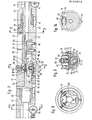
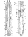
- the measuring probe 40 forms an elongated, cylindrical one Body with a central part 41 which is relative to the longitudinal axis of the measuring probe the end parts 42, 43 guided by the wheels 10, 11 can be rotated.
- the parts 41, 42, 43 are supported relative to one another by plain bearing pairs 45, 46 and 47, 48, which are each provided on the two outer ends of the probe end parts 42, 43 and support elongated axle shafts 50, 51, which are located on both outer ends of the middle Probe part 41 are integrally formed.
- the axle shaft 51 enclosed by the front end part 43 of the measuring probe simultaneously forms the actuating rod for rotating the central probe part 41 in the measuring position or out of the measuring position and is drilled along its length so that it can accommodate connecting cables (not shown) to the measuring device provided in the central probe part.
- the rotary movement takes place, for example, through an angle of 45 ° between the positions shown in FIGS. 5 and 6.
- Can be the previously mentioned stop cam 20 of the measuring tube are each arranged on both sides to the guide grooves 12, so that the measuring probe un g e-stops in the measuring tube 1 moves when the central probe portion of the driving position shown in Figure 5 occupies in Fig.. If the measuring wheel of the measuring device 54 of the piston of the measuring cell with the angular distance of 45 ° passes laterally 53, the tip 38, and have accordingly the counter-stops 55, the stop cam 20 passes the measuring tube, the average probe portion 41 by 45 0 in FIG. 6 The angular position shown is rotated and the probe is retracted until the counter stops 55 come into exact contact with the stop cams 20, as the diagram in FIG. 4 shows schematically.
- the exact contact with the stop cams 20 and thus the exact alignment of the measuring probe 40 to the measuring tube 1 is ensured by the spherical design of the surface of the counter-stops 55 and the conical design of the surface of the stop cams 20.
- the guide wheels 10, 11 of the measuring probe also contribute to a precise alignment, those with a relatively precisely set front support the measuring probe in the guide grooves 12 of the measuring tube. This spring preload is given by the mounting of the guide wheels 10, 11 shown in FIGS. 11 and 12 at the end of a leaf spring 57, 58.
- stop bolts 60, 61 which are fastened with an axially parallel course in the probe end parts 42, 43 and engage in a circumferential groove 62, 63 of the central probe part 41, the end faces of which lie opposite one another in the circumferential direction of the measuring probe, stop surfaces for the stop bolts 60, 61 form.
- the measuring wheel 53 thus moves under the crest 38 and thus pushes the piston 27 of the measuring cell 25, which forms the pressure-absorbing member, outward a small distance relative to the measuring tube, and the measuring device 54 of the measuring probe measures the force required for this or the force required to keep the piston against the outside pressure acting on it out of contact with the housing shoulder 32 of the measuring cell.
- the measuring wheel 53 is mounted on an axis 66 which is located at the end of a lever 65 is attached, which runs parallel to the longitudinal axis of the measuring probe and is pivotable about an axis 67 relative to the measuring probe.
- the pivoting range of the lever 65 is very limited, since the lever end carrying the measuring wheel 53 on a transmission member 68 of the measuring device and a stop pin 69 is provided at the opposite end of the lever 65.
- the stop bolt 69 is designed as a threaded bolt with a lock nut 70 so that the pivoting range of the lever can be adjusted radially outwards.
- the measuring device 54 is arranged in a longitudinal cutout 70 of the solid main body 71 of the central probe part 41 which is approximately square in cross section.
- This recess 70 is closed by a membrane 72, which is held by a closure body 73 on the main body 71 by means of screw bolts 74.
- the transmission member 68 forms a closed frame 75 arranged in the recess 70, which surrounds a measuring beam 76 and is fixedly connected to it by a screw bolt 77 with a lock nut 78.
- a threaded bolt 79 fastened to the outside of the frame 75 of the transmission member 68 extends through an opening in the membrane 72 and up to the end of the lever 65 supporting the measuring wheel 53, so that it moves or deflects the measuring wheel 53 on the measuring beam 76 can transmit.
- a screw nut 80 is screwed onto the threaded bolt 79 and presses a washer 81, which surrounds the screw bolt, in a sealing manner against the membrane 72, so that it is between the frame 75 and this disc
- the measuring bar 76 is fixed at one end by two screws 84, 85 to the solid main body 71 of the measuring probe, in such a way that this measuring bar end rests firmly against the recess 70 on a raised base part 86.
- the remaining part of the measuring bar for example starting from its center, is located at a short distance from a stepped bottom part 88 of the recess 70, so that it can be bent out by the measuring movement of the transmission member 68 firmly connected to it.
- the bending movement of the measuring bar is limited by an adjusting screw 89 forming a stop, which is enclosed by the screw bolt 77, which connects the measuring bar to the frame 75 of the transmission member 68.
- the end of the adjusting screw 89 comes to a stop in a bottom recess 90 of the recess 70.
- This bottom recess 90 is provided for receiving the lower part of the frame 75 surrounding the measuring bar.
- a play 91 of 0.3 mm is set by the adjusting screw 89, for example.
- the force measurement by means of the measuring bar 76 is carried out by determining its bending deformation, in that strain gauges are attached to the outside of the measuring bar in a certain area 92, the stretching of which leads to a change in an electrical resistance.
- a suitable arrangement of the strain gauges to several and their electrical connection in the form of a Wheatston bridge circuit enable high measurement accuracy.
- the area 92 of the measuring bar on which the bending movement is measured has a considerable cross-sectional weakening due to a recess 93 which extends in the longitudinal direction of the measuring bar and has an opening 94 on the outside opposite the free end 87 of the bar.
- the measuring bar thus has an inwardly directed free end 95 which runs parallel to the bending region 92.
- the frame 75 of the transmission member 68 is fastened to this free end in the manner described. Consequently, the bending deformation is transferred from this inward free end 95 to the bending area via the free outer beam end 87.
- Designated at 96 is a piece of an electrical cable leading through the axle shaft 51 to the outside, which creates the connection between the strain gauges and an electrical measuring device arranged on the outside.
- a piece of a cable 97 leading outward from the measuring probe 40 is also: indicated in Fig. 4.
- the measuring arrangement described for the force measurement can also be designed differently, in that instead of a measuring bar with strain gauges commercially available force sensors are used which, according to the ohmic capacitive, instructive or piezoelectric measuring principle, measure a measuring movement against the constant force of a spring element into an electrical one Convert measurement signal.
- Fig. 13 shows an embodiment of a sealing device 100, which compared to the use of a seal cuff 6 according to the illustration in Fig. 1 ensures a more reliable and perfect seal of the area in which the pressure measurement is to take place. This is of great importance for an accurate determination of the pressure in this area.
- the sealing device 100 consists of a pair of sleeves 103, 104 attached to the outside of the measuring tube 101 via flanges 102, which are filled by means of a filling line 105 from outside the borehole 106 with a hardening filling medium, for example cement mortar, so that they seal lay against the borehole wall 107.
- the filling medium flows into the sleeves 103, 104 via a filling valve mechanism 109, 110 clearly shown in FIG. 14.
- the valve mechanism has a rubber-elastic hose piece 114 which surrounds the return line 111 and thus a number of holes 113 provided therein, so that backflow into the return line is prevented.
- the filled sleeves 103, 104 seal a space 116 between them, which is then also filled with, for example, a hardening filling medium 117. Since the latter comes into direct contact with the possibly uneven borehole wall 107, a seal is obtained which is considerably better than the seal simply by pressing on a sleeve.
- a second filling line is for filling the space 116 119 provided with a return line 120.
- the return line has a filling valve mechanism 122, which is of the same design as that already described with reference to FIG. 14.
- the return line 120 has a venting mechanism 123, which has a fabric sleeve attached to it, which encloses a number of holes 125 in the return line 120.
- the fabric of the cuff 124 allows air and / or water to flow from the space 116 into the return line, but retains the filling medium there.
- a sealing device 100 of the type described above is provided on both sides of a measuring cell 25 ′′.
Landscapes
- Geology (AREA)
- Life Sciences & Earth Sciences (AREA)
- Engineering & Computer Science (AREA)
- Mining & Mineral Resources (AREA)
- Physics & Mathematics (AREA)
- Environmental & Geological Engineering (AREA)
- Fluid Mechanics (AREA)
- General Life Sciences & Earth Sciences (AREA)
- Geochemistry & Mineralogy (AREA)
- Geophysics (AREA)
- Measuring Fluid Pressure (AREA)
- Infusion, Injection, And Reservoir Apparatuses (AREA)
- Examining Or Testing Airtightness (AREA)
- Pens And Brushes (AREA)
Priority Applications (1)
| Application Number | Priority Date | Filing Date | Title |
|---|---|---|---|
| AT85114119T ATE50314T1 (de) | 1984-11-21 | 1985-11-06 | Verfahren zur messung von fluessigkeits- und gasdruck in einem abgedichteten bohrloch. |
Applications Claiming Priority (2)
| Application Number | Priority Date | Filing Date | Title |
|---|---|---|---|
| CH5556/84A CH666721A5 (de) | 1984-11-21 | 1984-11-21 | Verfahren zur messung von fluessigkeits- und gasdruck in einem abgedichteten bohrloch. |
| CH5556/84 | 1984-11-21 |
Publications (3)
| Publication Number | Publication Date |
|---|---|
| EP0184013A2 true EP0184013A2 (fr) | 1986-06-11 |
| EP0184013A3 EP0184013A3 (en) | 1988-03-30 |
| EP0184013B1 EP0184013B1 (fr) | 1990-02-07 |
Family
ID=4295558
Family Applications (1)
| Application Number | Title | Priority Date | Filing Date |
|---|---|---|---|
| EP85114119A Expired - Lifetime EP0184013B1 (fr) | 1984-11-21 | 1985-11-06 | Méthode pour la mesure de pression du liquide et du gaz dans un trou de sondage étanché |
Country Status (8)
| Country | Link |
|---|---|
| US (1) | US4643024A (fr) |
| EP (1) | EP0184013B1 (fr) |
| JP (1) | JPS61129544A (fr) |
| AT (1) | ATE50314T1 (fr) |
| BR (1) | BR8505816A (fr) |
| CA (1) | CA1261176A (fr) |
| CH (1) | CH666721A5 (fr) |
| DE (1) | DE3575969D1 (fr) |
Cited By (1)
| Publication number | Priority date | Publication date | Assignee | Title |
|---|---|---|---|---|
| CN121954318A (zh) * | 2026-04-01 | 2026-05-01 | 水利部牧区水利科学研究所 | 一种便携式滴灌带水压检测装置 |
Families Citing this family (13)
| Publication number | Priority date | Publication date | Assignee | Title |
|---|---|---|---|---|
| CH669427A5 (fr) * | 1985-01-24 | 1989-03-15 | Industrieorientierte Forsch | |
| US4840112A (en) * | 1988-01-12 | 1989-06-20 | Ga Technologies Inc. | Combined valve/cylinder using electro-rheological fluid |
| DE19804981A1 (de) * | 1998-02-07 | 1999-08-19 | Daimler Chrysler Ag | Mehrkomponenten-Meßrad |
| GB2359833B (en) | 2000-03-04 | 2004-02-18 | Abb Offshore Systems Ltd | Packer system |
| WO2004009957A1 (fr) * | 2002-07-23 | 2004-01-29 | Halliburton Energy Services, Inc. | Mesure de la pression et de la temperature d'un puis souterrain |
| US7159468B2 (en) * | 2004-06-15 | 2007-01-09 | Halliburton Energy Services, Inc. | Fiber optic differential pressure sensor |
| US9392907B2 (en) | 2012-05-01 | 2016-07-19 | Michael Allora | Bulk cooking oil distribution system |
| US9156390B2 (en) | 2012-05-01 | 2015-10-13 | Oilmatic Systems, Llc | Bulk cooking oil distribution system |
| EP2792842B1 (fr) * | 2013-04-16 | 2016-02-24 | GE Oil & Gas UK Limited | Calcul de la température de fond de trou |
| CN104265256A (zh) * | 2014-07-31 | 2015-01-07 | 中国石油天然气股份有限公司 | 火烧油层电点火装置 |
| CN105927205B (zh) * | 2016-04-20 | 2023-03-24 | 中国石油天然气集团有限公司 | 连续油管水平井多参数产出工作筒 |
| CN109917101A (zh) * | 2019-04-12 | 2019-06-21 | 中国矿业大学(北京) | 基于上向穿层钻孔同时测定多煤层瓦斯含量的方法 |
| CN112343582B (zh) * | 2020-11-02 | 2023-01-31 | 大庆油田有限责任公司 | 一种井下内外压力监测装置 |
Family Cites Families (10)
| Publication number | Priority date | Publication date | Assignee | Title |
|---|---|---|---|---|
| US2793524A (en) * | 1954-11-17 | 1957-05-28 | Exxon Research Engineering Co | Tubing joint leak detector |
| US2964942A (en) * | 1958-09-08 | 1960-12-20 | Shell Oil Co | Bottom-hole pressure testing apparatus |
| US3283584A (en) * | 1963-10-28 | 1966-11-08 | James R Coffing | Adjustable pressure adaptor and sensing device |
| CH474761A (de) * | 1967-11-08 | 1969-06-30 | Kistler Instrumente Ag | Druckwandler |
| US3974690A (en) * | 1975-10-28 | 1976-08-17 | Stewart & Stevenson Oiltools, Inc. | Method of and apparatus for measuring annulus pressure in a well |
| US4204426A (en) * | 1978-11-13 | 1980-05-27 | Westbay Instruments Ltd. | Measuring casing coupler apparatus |
| US4192181A (en) * | 1978-11-13 | 1980-03-11 | Westbay Instruments Ltd. | Casing assembly probes |
| US4230180A (en) * | 1978-11-13 | 1980-10-28 | Westbay Instruments Ltd. | Isolating packer units in geological and geophysical measuring casings |
| US4480690A (en) * | 1981-02-17 | 1984-11-06 | Geo Vann, Inc. | Accelerated downhole pressure testing |
| US4392376A (en) * | 1981-03-31 | 1983-07-12 | S-Cubed | Method and apparatus for monitoring borehole conditions |
-
1984
- 1984-11-21 CH CH5556/84A patent/CH666721A5/de not_active IP Right Cessation
-
1985
- 1985-10-18 JP JP60233124A patent/JPS61129544A/ja active Pending
- 1985-11-06 AT AT85114119T patent/ATE50314T1/de not_active IP Right Cessation
- 1985-11-06 EP EP85114119A patent/EP0184013B1/fr not_active Expired - Lifetime
- 1985-11-06 DE DE8585114119T patent/DE3575969D1/de not_active Expired - Fee Related
- 1985-11-18 US US06/799,473 patent/US4643024A/en not_active Expired - Fee Related
- 1985-11-20 CA CA000495758A patent/CA1261176A/fr not_active Expired
- 1985-11-20 BR BR8505816A patent/BR8505816A/pt unknown
Cited By (1)
| Publication number | Priority date | Publication date | Assignee | Title |
|---|---|---|---|---|
| CN121954318A (zh) * | 2026-04-01 | 2026-05-01 | 水利部牧区水利科学研究所 | 一种便携式滴灌带水压检测装置 |
Also Published As
| Publication number | Publication date |
|---|---|
| DE3575969D1 (de) | 1990-03-15 |
| BR8505816A (pt) | 1986-08-12 |
| ATE50314T1 (de) | 1990-02-15 |
| CA1261176A (fr) | 1989-09-26 |
| JPS61129544A (ja) | 1986-06-17 |
| US4643024A (en) | 1987-02-17 |
| EP0184013A3 (en) | 1988-03-30 |
| CH666721A5 (de) | 1988-08-15 |
| EP0184013B1 (fr) | 1990-02-07 |
Similar Documents
| Publication | Publication Date | Title |
|---|---|---|
| EP0184013B1 (fr) | Méthode pour la mesure de pression du liquide et du gaz dans un trou de sondage étanché | |
| DE69209479T2 (de) | Vorrichtung zur Kontrolle der Abmessungen eines Objektes, insbesondere des externen oder internen Durchmessers eines mechanischen Teils | |
| DE2404011A1 (de) | Bodensonde | |
| DE2529552A1 (de) | Vorrichtung zum messen der auf ein drehteil ausgeuebten radialbelastung | |
| DD287575A5 (de) | Einrichtung zum messen der bahnspannung einer warenbahn | |
| DE2439662A1 (de) | Vorrichtung zum zerstoerungsfreien pruefen von metallischen rohlingen auf oberflaechenfehler | |
| DE2407510A1 (de) | Walze mit durchbiegungsausgleich | |
| DE2920886A1 (de) | Verfahren und einrichtung zum bestimmen von verschiebungen im gelaende und in bauwerken | |
| DE2631698C2 (de) | Kraftmeßwandler | |
| DE3780021T2 (de) | Messvorrichtung zur messung eines parameters, z.b. der konsistenz, einer substanz in einem fliessprozess. | |
| DE2613995A1 (de) | Lagerbaugruppe fuer messgeraete | |
| DE2941855C2 (fr) | ||
| DE69002693T2 (de) | Hydraulische Drehverbindung mit hydrostatischem Ausgleich. | |
| DE2815436C2 (de) | Halterung für eine stabartig ausgebildete Sonde an einer Leitung für ein Strömungsmittel | |
| CH669427A5 (fr) | ||
| DE3141655C2 (de) | Präzisions-Potentiometerkupplung | |
| EP1044356B1 (fr) | Dynamometre | |
| DE19524377C2 (de) | Prüfpumpe zur Druckerzeugung beim Prüfen von Druckmeßgeräten | |
| EP0632881A1 (fr) | Procede de determination de l'extension d'un objet au moyen d'un capteur extensometrique, application dudit procede et capteur de mesure d'allongement correspondant. | |
| DE3320057A1 (de) | Bedienelement | |
| DE69914281T2 (de) | Verfahren und Vorrichtung zur Kontrolle der Dichtigkeit einer Aufschüttung | |
| DE2810185C2 (de) | Wäge- oder Prüfvorrichtung mit einem Lasthebel | |
| EP0163247A2 (fr) | Indicateur de réglage des cyclindres | |
| DE2250902C3 (de) | Vorrichtung zum Messen der Walzkraft an Walzgerüsten | |
| DE2906170C2 (de) | Extensometer für die Fels- und Bodenmechanik |
Legal Events
| Date | Code | Title | Description |
|---|---|---|---|
| PUAI | Public reference made under article 153(3) epc to a published international application that has entered the european phase |
Free format text: ORIGINAL CODE: 0009012 |
|
| AK | Designated contracting states |
Kind code of ref document: A2 Designated state(s): AT DE FR GB IT SE |
|
| PUAL | Search report despatched |
Free format text: ORIGINAL CODE: 0009013 |
|
| RHK1 | Main classification (correction) |
Ipc: E21B 47/06 |
|
| AK | Designated contracting states |
Kind code of ref document: A3 Designated state(s): AT DE FR GB IT SE |
|
| 17P | Request for examination filed |
Effective date: 19880311 |
|
| 17Q | First examination report despatched |
Effective date: 19890605 |
|
| GRAA | (expected) grant |
Free format text: ORIGINAL CODE: 0009210 |
|
| AK | Designated contracting states |
Kind code of ref document: B1 Designated state(s): AT DE FR GB IT SE |
|
| REF | Corresponds to: |
Ref document number: 50314 Country of ref document: AT Date of ref document: 19900215 Kind code of ref document: T |
|
| REF | Corresponds to: |
Ref document number: 3575969 Country of ref document: DE Date of ref document: 19900315 |
|
| GBT | Gb: translation of ep patent filed (gb section 77(6)(a)/1977) | ||
| ET | Fr: translation filed | ||
| ITF | It: translation for a ep patent filed | ||
| PGFP | Annual fee paid to national office [announced via postgrant information from national office to epo] |
Ref country code: SE Payment date: 19901025 Year of fee payment: 6 |
|
| PGFP | Annual fee paid to national office [announced via postgrant information from national office to epo] |
Ref country code: AT Payment date: 19901030 Year of fee payment: 6 |
|
| PG25 | Lapsed in a contracting state [announced via postgrant information from national office to epo] |
Ref country code: GB Effective date: 19901106 |
|
| PLBE | No opposition filed within time limit |
Free format text: ORIGINAL CODE: 0009261 |
|
| STAA | Information on the status of an ep patent application or granted ep patent |
Free format text: STATUS: NO OPPOSITION FILED WITHIN TIME LIMIT |
|
| ITTA | It: last paid annual fee | ||
| 26N | No opposition filed | ||
| GBPC | Gb: european patent ceased through non-payment of renewal fee | ||
| PG25 | Lapsed in a contracting state [announced via postgrant information from national office to epo] |
Ref country code: FR Effective date: 19910731 |
|
| REG | Reference to a national code |
Ref country code: FR Ref legal event code: ST |
|
| PGFP | Annual fee paid to national office [announced via postgrant information from national office to epo] |
Ref country code: DE Payment date: 19911015 Year of fee payment: 7 |
|
| PG25 | Lapsed in a contracting state [announced via postgrant information from national office to epo] |
Ref country code: AT Effective date: 19911106 |
|
| PG25 | Lapsed in a contracting state [announced via postgrant information from national office to epo] |
Ref country code: SE Effective date: 19911107 |
|
| PG25 | Lapsed in a contracting state [announced via postgrant information from national office to epo] |
Ref country code: DE Effective date: 19930803 |
|
| EUG | Se: european patent has lapsed |
Ref document number: 85114119.2 Effective date: 19920604 |