EP0184014A1 - Treibsatzanordnung für einen Feststoffraketenmotor - Google Patents
Treibsatzanordnung für einen Feststoffraketenmotor Download PDFInfo
- Publication number
- EP0184014A1 EP0184014A1 EP85114120A EP85114120A EP0184014A1 EP 0184014 A1 EP0184014 A1 EP 0184014A1 EP 85114120 A EP85114120 A EP 85114120A EP 85114120 A EP85114120 A EP 85114120A EP 0184014 A1 EP0184014 A1 EP 0184014A1
- Authority
- EP
- European Patent Office
- Prior art keywords
- grain
- igniter
- propellant
- main
- flutes
- Prior art date
- Legal status (The legal status is an assumption and is not a legal conclusion. Google has not performed a legal analysis and makes no representation as to the accuracy of the status listed.)
- Granted
Links
- 239000003380 propellant Substances 0.000 title claims abstract description 44
- 239000004449 solid propellant Substances 0.000 title claims description 6
- 239000007789 gas Substances 0.000 claims abstract description 10
- 238000002485 combustion reaction Methods 0.000 claims abstract description 4
- 230000009467 reduction Effects 0.000 claims abstract description 4
- 230000007246 mechanism Effects 0.000 claims abstract description 3
- 230000000694 effects Effects 0.000 abstract description 3
- 230000008901 benefit Effects 0.000 description 6
- 239000000463 material Substances 0.000 description 4
- 238000000034 method Methods 0.000 description 4
- 239000003999 initiator Substances 0.000 description 3
- 239000013618 particulate matter Substances 0.000 description 3
- 230000008569 process Effects 0.000 description 3
- 230000000750 progressive effect Effects 0.000 description 3
- 238000010304 firing Methods 0.000 description 2
- 238000009472 formulation Methods 0.000 description 2
- 239000000203 mixture Substances 0.000 description 2
- 239000008188 pellet Substances 0.000 description 2
- 239000000779 smoke Substances 0.000 description 2
- 229910000831 Steel Inorganic materials 0.000 description 1
- 230000009471 action Effects 0.000 description 1
- 230000002411 adverse Effects 0.000 description 1
- XAGFODPZIPBFFR-UHFFFAOYSA-N aluminium Chemical compound [Al] XAGFODPZIPBFFR-UHFFFAOYSA-N 0.000 description 1
- 229910052782 aluminium Inorganic materials 0.000 description 1
- 239000004411 aluminium Substances 0.000 description 1
- 230000004888 barrier function Effects 0.000 description 1
- 230000015572 biosynthetic process Effects 0.000 description 1
- 239000004568 cement Substances 0.000 description 1
- 230000008859 change Effects 0.000 description 1
- 239000000567 combustion gas Substances 0.000 description 1
- 238000009833 condensation Methods 0.000 description 1
- 230000005494 condensation Effects 0.000 description 1
- 238000010276 construction Methods 0.000 description 1
- PXBRQCKWGAHEHS-UHFFFAOYSA-N dichlorodifluoromethane Chemical compound FC(F)(Cl)Cl PXBRQCKWGAHEHS-UHFFFAOYSA-N 0.000 description 1
- 235000019404 dichlorodifluoromethane Nutrition 0.000 description 1
- 230000003628 erosive effect Effects 0.000 description 1
- 239000011521 glass Substances 0.000 description 1
- 238000009434 installation Methods 0.000 description 1
- 239000012212 insulator Substances 0.000 description 1
- 238000004519 manufacturing process Methods 0.000 description 1
- 230000003287 optical effect Effects 0.000 description 1
- ISWSIDIOOBJBQZ-UHFFFAOYSA-N phenol group Chemical group C1(=CC=CC=C1)O ISWSIDIOOBJBQZ-UHFFFAOYSA-N 0.000 description 1
- 239000004033 plastic Substances 0.000 description 1
- 230000001681 protective effect Effects 0.000 description 1
- 230000004044 response Effects 0.000 description 1
- 238000000926 separation method Methods 0.000 description 1
- 230000035939 shock Effects 0.000 description 1
- 239000007787 solid Substances 0.000 description 1
- 239000010959 steel Substances 0.000 description 1
- 230000036642 wellbeing Effects 0.000 description 1
Images



Classifications
-
- F—MECHANICAL ENGINEERING; LIGHTING; HEATING; WEAPONS; BLASTING
- F02—COMBUSTION ENGINES; HOT-GAS OR COMBUSTION-PRODUCT ENGINE PLANTS
- F02K—JET-PROPULSION PLANTS
- F02K9/00—Rocket-engine plants, i.e. plants carrying both fuel and oxidant therefor; Control thereof
- F02K9/08—Rocket-engine plants, i.e. plants carrying both fuel and oxidant therefor; Control thereof using solid propellants
- F02K9/10—Shape or structure of solid propellant charges
- F02K9/18—Shape or structure of solid propellant charges of the internal-burning type having a star or like shaped internal cavity
-
- F—MECHANICAL ENGINEERING; LIGHTING; HEATING; WEAPONS; BLASTING
- F02—COMBUSTION ENGINES; HOT-GAS OR COMBUSTION-PRODUCT ENGINE PLANTS
- F02K—JET-PROPULSION PLANTS
- F02K9/00—Rocket-engine plants, i.e. plants carrying both fuel and oxidant therefor; Control thereof
- F02K9/95—Rocket-engine plants, i.e. plants carrying both fuel and oxidant therefor; Control thereof characterised by starting or ignition means or arrangements
Definitions
- the invention relates to a propellant configuration for a solid propellant rocket motor, in accordance with the prior art portion of claim 1.
- the rocket motor it is desirable at the time an air launched vehicle is being fired, for the rocket motor to quickly accelerate the missile from the launch rail or launch rack, such that a clean separation will be obtained. It is also desirable, as the missile moves ahead of the launching aircraft, for the amount of rocket exhaust, including solid particulates being ingested into the engine of the aircraft, to be minimized.
- the invention as claimed is intended to remedy these drawbacks. It solves the problem of how to design a propellant configuration for a rocket motor serving to provide the desired thrust characteristics as well as to minimize the problems of the launching aircraft, soldier, or launch canister.
- This invention represents a design advantageously combining a high mass flow rate motor igniter with a high mass flow rate main propellant grain design, thereby to produce the initial high level of total impulse required to accelerate a certain missile to a velocity of 120 feet per second (36,6m/s) within a canister length of under 7 feet (2,lm).
- the igniter propellant is totally consumed, as are the flutes of the main grain, this resulting in a desired lowering of the thrust level.
- the rocket motor then burns normally in a progressive manner to produce the required missile velocity at burnout. Quite advantageously, all of the above is initiated by a single electrical signal from the launch command equipment, and accomplished within a common pressure vessel (i.e., no separate eject motor is required).
- Fig.l shows certain internal portions of a rocket motor propulsion arrangement 10 in accordance with the invention, including the principal portion of solid propellant 12, also known as the main grain, which is generally in the configuration of a cylinder contained in a motor casing 14, of the type used in a missile.
- the main grain 12 is symmetrically disposed about the longitudinal centerline 18 of the rocket motor, and has a central bore or cavity 16 therein.
- the onset of burning of the main grain 12 at the time of missile launch commences in the central cavity 16 of the propellant, with the flow of hot gases that result from the burning process traveling toward the right as viewed in Fig.l, along the centerline 18 and out through nozzle 19. As a result, the missile travels to the left as viewed in Fig.l. Burning of the main grain 12 is caused to commence at the desired time by the use of the igniter or igniter assembly 20, disposed in the central cavity 16, along the centerline 18.
- Fig.2 shows substantial details of the igniter assembly 20 utilized in accordance with the invention.
- hot gases are caused to emanate from the central port 22 on the aft face of the igniter 20, which causes the flutes 24 of the central portion of the main grain 12 to commence burning.
- Hot gases also emanate from a plurality of ports or holes 26 arrayed about the forward end of the igniter 20, that is, the end of the igniter 20 remote from the central port 22.
- These ports 26 are preferably circumferentially spaced, and some 1/8 inch (3mm) in diameter, with the hot gases from these ports 26 causing ignition of the solid propellant at the closed end of the cavity 16.
- Internal construction of the igniter assembly 20 will shortly be described to a fuller extent.
- the heart of the invention involves the fact that the propellant grain design of the igniter 20 and the propellant grain design of the main grain 12 are carefully sized so as to produce the high mass flow rate (total impulse) required to eject the missile from the launch means.
- the igniter propellant by design has been totally consumed, and the flutes have disappeared from the main grain 12, leaving only a generally cylindrical main grain configuration, having a desirable burn characteristic, for furnishing propulsion to the missile.
- the igniter assembly 20 is directly supported from the safe and arm device 28, which is generally circular, and mounted on the motor casing 14 at the forward end of the main grain 12.
- the safe and arm device 28 is designed to prevent accidental ignition of the igniter, but functions to bring about actuation of the igniter at the desired time.
- An initiator 30 screwed into a lower portion of the safe and arm device 28, and an electrical connector 32 connected thereto by electrical leads 33 make possible the firing of the igniter by means of an electrical signal provided from a remote location; note also the details in Fig.3.
- the safe and arm device 28 is a conventional in-line, out-of-line barrier device serving to prevent inadvertent ignition of the motor. Since it is not per se a part of the invention, it is not illustrated herein. A safe and arm device manufactured by any of several well known companies would be sufficient in this instance.
- an arming electrical signal is transmitted to a solenoid, causing its internal mechanism to rotate some 45 degrees.
- a solenoid shaft extension is driven in rotation by the solenoid motion.
- a hole in the shaft is normally out of alignment with a pin, but upon the shaft being rotated by the solenoid action, the hole aligns with the pin.
- combustion gases from the initiator force the pin into the hole in the shaft, thereby exposing a hole in the safe and arm housing, latter hole leading to the booster charge in the cavity in the ignitor housing.
- BKN0 3 pellets are used, with the burning of such pellets causing an intense flame exiting through a perforate steel plate 29, into the igniter main cavity, this of course causing prompt ignition of the igniter propellant.
- the fire command can be executed from 0 - 10 seconds after the solenoid has been actuated to expose the hole in the housing of the safe and arm device.
- a threaded mounting ring 34 for supporting the safe and arm device 28 and the igniter assembly 20 is utilized with ring 34 being visible in Fig.2, and also being known as an adapter ring.
- the ring 34 is provided with external threads 36, which are closely received in internal threads 38 disposed around the interior of the end of the motor casing 14.
- a circumferential shoulder 42 is provided near the forward end of the adapter ring 24, and this shoulder is brought up flush with the forward flange of the motor casing 14 during ring installation. Undesired leakage between the threads is prevented by providing a circumferential groove adjacent the rear edge of the adapter ring 34, in which groove is disposed an O-ring 44.
- the adapter ring 34 may be made of aluminium or the like in the interests of lightness, and integrity thereof during motor burn is assured by the use of a thermal insulator 46 serving as a protective member.
- the member 46 is of generally toroidal configuration, and is made of a rubber designed to withstand high temperature, such as 6000° R (3060°C) for the requisite burn time which normally is less than 5 seconds.
- the safe and arm device 28 is provided with a circular mounting flange 48 that is closely received in the interior bore of the adapter ring 34.
- the mounting flange 48 is provided with a circular exterior groove 52, in which O-ring 54 is disposed.
- Latter O-Ring prevents high pressure, high temperature gas from flowing forwardly from the central cavity 16.
- Undesired movement of the flange 48 away from the illustrated position is prevented by the use of snap ring 56, received in a suitable groove in the interior bore of the adapter ring 34.
- a retaining ring key 57 is used that prevents the snap ring 56 being dislodged.
- the key 57 is best shown in Fig.3.
- the igniter serves the important functions of igniting the main grain 12 on command, and providing the additional mass flow rate to perform the missile eject process.
- the generally cylindrical outer case 62 of the igniter is preferably made of high temperature resistant material such as glass . phenolic, for this latter material is not appreciably damaged by the high temperature combustion taking place inside the igniter as well as around its circumference.
- igniter propellant 64 Interiorally of the igniter case 62 is an igniter propellant 64 which, quite importantly, is the same propellant as the main grain 12 utilized in the motor casing 14.
- the configuration of the propellant 64 will be discussed shortly, in connection with Fig.4.
- a minimum smoke, composite-modified double base propellant is to be used, inasmuch as this propellant offers high energy content per pound, the desired high burn rate, and produces a minimum quantity of smoke and plume particulates.
- particulates harm laser efforts by absorbing laser energy, and impact adversely the S/N (signal/noise) ratio at the detector receivers.
- nozzle member 66 Secured in the aft end of the generally cylindrical outer igniter case 62 as shown in Fig.2 is nozzle member 66, the central aperture 22 of which is configured to produce a specific angle of igniter emitted gases, thus to enhance ignition of the flutes 24 of the main grain 12.
- the nozzle is preferably made of silica-phenolic material, and is held in place in the aft end of the igniter case by the use of cement, as well as by a plurality of radially disposed pins 68.
- a plastic plug 70 is installed in the igniter nozzle, which serves to increase the pressure rise rate of the igniter.
- the plug 70 is blown out only at such time as pressure has built up in the interior of the igniter assembly 20 to a desirably high value.
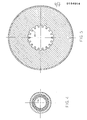
- the interior portion of propellant 64 of the igniter 20 is provided with a plurality of flutes 74 spaced about the centerline of the igniter 20. These flutes desirably increase the surface area over which intense burning can take place at the time of missile launch.
- a plurality of flutes 74 spaced about the centerline of the igniter 20. These flutes desirably increase the surface area over which intense burning can take place at the time of missile launch.
- Fig.5 there is likewise provided the central portion of the main grain 12 with flutes 24, as was mentioned in connection with Fig.2.
- the burn area is desirably increased during the relatively brief igniter burn.
- Fig.6a there is shown to a somewhat larger scale a typical flute of the type utilized in the igniter 20, with this view revealing the progressive burning thereof. It is important to note that the entire illustrated portion of the igniter 20 has been consumed by the time the flute portion of the main grain 12 has burned away. Similarly, in Fig.6b, there is shown to the same time scale, the progressive burning of a typical flute 24 of the main grain 12, with it to be noted that a considerable portion of the propellant of the main grain 12 still remains after the igniter propellant 64 and the flutes 24 of the main grain 12 have burned away.
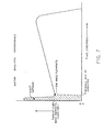
- Fig.7 represents a plot of mass flow rate versus time, with this graph clearly revealing the large initial thrust, followed after burnout of the igniter 20 by a sharp drop to a level representing the thrust provided by main grain 12 burning after burnaway of the flutes 24.
- the sharp drop usually takes place approximately .10 to .12 seconds after ignition.
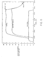
- Fig.8 shows in greater detail, the interrelationship of the burn time of the flutes 24 of the main grain 12, and 0184014 the igniter 20.
- the entire igniter 20 has been consumed by the time the flutes 24 of the main grain 12 have burned away, with these events taking place by the time the missile leaves the launch tube.
- the geometrical design implementation of the invention may be defined as follows:
- the burn surface area (A b ) of the main grain at motor ignition is found to be (Prior to T o of Fig.6b):
- the burn surface area of the igniter grain immediately after igniter propellant burnout is 0.0 IN (T 0 + T 2 of Fig.6a).
- Mass flow rate (w) is essentially proportional to chamber operating pressure, and motor thrust is related to operating chamber pressure via the expression
Landscapes
- Engineering & Computer Science (AREA)
- Chemical & Material Sciences (AREA)
- Combustion & Propulsion (AREA)
- Mechanical Engineering (AREA)
- General Engineering & Computer Science (AREA)
- Aiming, Guidance, Guns With A Light Source, Armor, Camouflage, And Targets (AREA)
- Feeding, Discharge, Calcimining, Fusing, And Gas-Generation Devices (AREA)
- Solid Fuels And Fuel-Associated Substances (AREA)
Applications Claiming Priority (2)
| Application Number | Priority Date | Filing Date | Title |
|---|---|---|---|
| US67893784A | 1984-12-06 | 1984-12-06 | |
| US678937 | 1984-12-06 |
Publications (2)
| Publication Number | Publication Date |
|---|---|
| EP0184014A1 true EP0184014A1 (de) | 1986-06-11 |
| EP0184014B1 EP0184014B1 (de) | 1988-04-27 |
Family
ID=24724945
Family Applications (1)
| Application Number | Title | Priority Date | Filing Date |
|---|---|---|---|
| EP85114120A Expired EP0184014B1 (de) | 1984-12-06 | 1985-11-06 | Treibsatzanordnung für einen Feststoffraketenmotor |
Country Status (7)
| Country | Link |
|---|---|
| EP (1) | EP0184014B1 (de) |
| CA (1) | CA1255509A (de) |
| DE (1) | DE3562408D1 (de) |
| DK (1) | DK157462C (de) |
| ES (1) | ES8703623A1 (de) |
| IL (1) | IL77017A0 (de) |
| NO (1) | NO164195C (de) |
Cited By (9)
| Publication number | Priority date | Publication date | Assignee | Title |
|---|---|---|---|---|
| US5656587A (en) * | 1982-09-24 | 1997-08-12 | The United States Of America As Represented By The Secretary Of The Department Of Health And Human Services | Promotion of cell proliferation by use of transforming growth factor beta (TGF-β) |
| US5705477A (en) * | 1982-09-24 | 1998-01-06 | The United States Of America As Represented By The Department Of Health And Human Services | Compositions of transforming growth factor β(TGF-β) which promotes wound healing and methods for their use |
| RU2145674C1 (ru) * | 1999-06-10 | 2000-02-20 | Пермский завод им.С.М.Кирова | Заряд ракетного твердого топлива |
| RU2145673C1 (ru) * | 1999-05-25 | 2000-02-20 | Пермский завод им.С.М.Кирова | Заряд ракетного твердого топлива |
| DE4018794C2 (de) * | 1989-06-15 | 2000-06-08 | Poudres Et Explosifs Paris Soc | Triebwerk mit einem Propergolblock, der mit einem Mittenkanal mit veränderlichem Querschnitt versehen ist |
| RU2150599C1 (ru) * | 1999-10-14 | 2000-06-10 | Федеральное государственное унитарное предприятие Пермский завод им. С.М. Кирова | Заряд ракетного твердого топлива |
| RU2178092C2 (ru) * | 1999-11-01 | 2002-01-10 | Государственное унитарное предприятие "Научно-исследовательский институт полимерных материалов" | Заряд твердого топлива для ракетного двигателя |
| CN111810318A (zh) * | 2020-06-28 | 2020-10-23 | 北京凌空天行科技有限责任公司 | 一种单室双推力固体火箭发动机及火箭 |
| CN113958424A (zh) * | 2021-08-20 | 2022-01-21 | 西安零壹空间科技有限公司 | 一种内弹道曲线无翘尾现象的火箭助推发动机 |
Families Citing this family (3)
| Publication number | Priority date | Publication date | Assignee | Title |
|---|---|---|---|---|
| DE102015106822A1 (de) | 2015-04-30 | 2016-11-03 | Bayern-Chemie Gesellschaft Für Flugchemische Antriebe Mbh | Motorantrieb mit hohen Boost/Sustain-Schubverhältnissen |
| CN106050476B (zh) * | 2016-07-11 | 2018-06-05 | 湖北三江航天江河化工科技有限公司 | 一种液体火箭发动机点火装置及其点火方法 |
| CN114060168B (zh) * | 2021-11-05 | 2024-01-19 | 江西洪都航空工业集团有限责任公司 | 一种大初始推力端燃装药固体火箭发动机 |
Citations (5)
| Publication number | Priority date | Publication date | Assignee | Title |
|---|---|---|---|---|
| DE1149284B (de) * | 1961-09-28 | 1963-05-22 | Josef Schaberger & Co G M B H | Verfahren und Vorrichtung zum Zuenden von Innenbrenner-Raketentreibladungen |
| US3107487A (en) * | 1960-08-12 | 1963-10-22 | Aerojet General Co | Rocket motor |
| US3951072A (en) * | 1968-09-12 | 1976-04-20 | The United States Of America As Represented By The Secretary Of The Navy | Propellant grain |
| US4015427A (en) * | 1975-11-12 | 1977-04-05 | The United States Of America As Represented By The Secretary Of The Air Force | Fuel grain for spherical boost-sustain rocket motor |
| US4068591A (en) * | 1976-03-10 | 1978-01-17 | The United States Of America As Represented By The Secretary Of The Army | Ignition system used in testing solid propellant compositions for smokelessness |
Family Cites Families (1)
| Publication number | Priority date | Publication date | Assignee | Title |
|---|---|---|---|---|
| FR2500149B1 (fr) * | 1981-02-17 | 1985-12-06 | Poudres & Explosifs Ste Nale | Chargement propulsif biregime a canal en trompette comportant une section en etoile |
-
1985
- 1985-11-06 DE DE8585114120T patent/DE3562408D1/de not_active Expired
- 1985-11-06 EP EP85114120A patent/EP0184014B1/de not_active Expired
- 1985-11-12 IL IL77017A patent/IL77017A0/xx unknown
- 1985-12-02 CA CA000496656A patent/CA1255509A/en not_active Expired
- 1985-12-05 DK DK563985A patent/DK157462C/da not_active IP Right Cessation
- 1985-12-05 NO NO854913A patent/NO164195C/no unknown
- 1985-12-05 ES ES549623A patent/ES8703623A1/es not_active Expired
Patent Citations (5)
| Publication number | Priority date | Publication date | Assignee | Title |
|---|---|---|---|---|
| US3107487A (en) * | 1960-08-12 | 1963-10-22 | Aerojet General Co | Rocket motor |
| DE1149284B (de) * | 1961-09-28 | 1963-05-22 | Josef Schaberger & Co G M B H | Verfahren und Vorrichtung zum Zuenden von Innenbrenner-Raketentreibladungen |
| US3951072A (en) * | 1968-09-12 | 1976-04-20 | The United States Of America As Represented By The Secretary Of The Navy | Propellant grain |
| US4015427A (en) * | 1975-11-12 | 1977-04-05 | The United States Of America As Represented By The Secretary Of The Air Force | Fuel grain for spherical boost-sustain rocket motor |
| US4068591A (en) * | 1976-03-10 | 1978-01-17 | The United States Of America As Represented By The Secretary Of The Army | Ignition system used in testing solid propellant compositions for smokelessness |
Non-Patent Citations (2)
| Title |
|---|
| H. MIELKE: "Raketentechnik, eine Einführung", 1959, pages 77-79, VEB Verlag Technik, Berlin, DE * |
| H.G. MÜNZBERG: "Flugantriebe, Grundlagen, Systematik und Technik der Luft- und Raumfahrtantriebe", 1972, pages 432-433, Springer-Verlag, Berlin, Heidelberg, DE * |
Cited By (10)
| Publication number | Priority date | Publication date | Assignee | Title |
|---|---|---|---|---|
| US5656587A (en) * | 1982-09-24 | 1997-08-12 | The United States Of America As Represented By The Secretary Of The Department Of Health And Human Services | Promotion of cell proliferation by use of transforming growth factor beta (TGF-β) |
| US5705477A (en) * | 1982-09-24 | 1998-01-06 | The United States Of America As Represented By The Department Of Health And Human Services | Compositions of transforming growth factor β(TGF-β) which promotes wound healing and methods for their use |
| DE4018794C2 (de) * | 1989-06-15 | 2000-06-08 | Poudres Et Explosifs Paris Soc | Triebwerk mit einem Propergolblock, der mit einem Mittenkanal mit veränderlichem Querschnitt versehen ist |
| RU2145673C1 (ru) * | 1999-05-25 | 2000-02-20 | Пермский завод им.С.М.Кирова | Заряд ракетного твердого топлива |
| RU2145674C1 (ru) * | 1999-06-10 | 2000-02-20 | Пермский завод им.С.М.Кирова | Заряд ракетного твердого топлива |
| RU2150599C1 (ru) * | 1999-10-14 | 2000-06-10 | Федеральное государственное унитарное предприятие Пермский завод им. С.М. Кирова | Заряд ракетного твердого топлива |
| RU2178092C2 (ru) * | 1999-11-01 | 2002-01-10 | Государственное унитарное предприятие "Научно-исследовательский институт полимерных материалов" | Заряд твердого топлива для ракетного двигателя |
| CN111810318A (zh) * | 2020-06-28 | 2020-10-23 | 北京凌空天行科技有限责任公司 | 一种单室双推力固体火箭发动机及火箭 |
| CN113958424A (zh) * | 2021-08-20 | 2022-01-21 | 西安零壹空间科技有限公司 | 一种内弹道曲线无翘尾现象的火箭助推发动机 |
| CN113958424B (zh) * | 2021-08-20 | 2022-12-06 | 西安零壹空间科技有限公司 | 一种内弹道曲线无翘尾现象的火箭助推发动机 |
Also Published As
| Publication number | Publication date |
|---|---|
| ES549623A0 (es) | 1987-02-16 |
| DK563985A (da) | 1986-06-07 |
| NO164195B (no) | 1990-05-28 |
| ES8703623A1 (es) | 1987-02-16 |
| DK157462C (da) | 1990-06-05 |
| DE3562408D1 (en) | 1988-06-01 |
| CA1255509A (en) | 1989-06-13 |
| DK157462B (da) | 1990-01-08 |
| NO854913L (no) | 1986-06-09 |
| IL77017A0 (en) | 1986-04-29 |
| NO164195C (no) | 1990-09-05 |
| DK563985D0 (da) | 1985-12-05 |
| EP0184014B1 (de) | 1988-04-27 |
Similar Documents
| Publication | Publication Date | Title |
|---|---|---|
| US4738100A (en) | Boost-sustain-boost rocket | |
| EP0184014B1 (de) | Treibsatzanordnung für einen Feststoffraketenmotor | |
| US2624281A (en) | Projectile | |
| US4722261A (en) | Extendable ram cannon | |
| GB669014A (en) | Improvements relating to jet-propelled missiles | |
| US3167016A (en) | Rocket propelled missile | |
| US4972673A (en) | Solid rocket motor with dual interrupted thrust | |
| US3442084A (en) | Multistage solid fuel rocket propulsion unit for the placing of depth charges | |
| US3044255A (en) | Powder propulsive for rockets or other self-propelled projectiles | |
| JPH0347426B2 (de) | ||
| JPH0411800B2 (de) | ||
| US4078495A (en) | Control after burnout for reaction steered missiles | |
| EP0268566A3 (de) | Basis-Ausströmeinheit | |
| FI93576B (fi) | Perävirtauslaitteen järjestely | |
| US2598256A (en) | Recoilless gun | |
| JPS5914720B2 (ja) | 反動推進式ビ−クル用発射組立体 | |
| US5322002A (en) | Tube launched weapon system | |
| US3326128A (en) | Rockets and combinations of rockets and cases | |
| US3903802A (en) | Shell construction sealing washer | |
| US3404532A (en) | Self-sealing through-nozzle transfer system | |
| RU2062343C1 (ru) | Ракетный двигатель твердого топлива | |
| RU2133864C1 (ru) | Ракетный двигатель твердого топлива | |
| US2683415A (en) | Rocket motor | |
| RU2230211C1 (ru) | Пиропатрон для катапультного кресла пилотируемого летательного аппарата | |
| US3185096A (en) | Thrust reversal unit for rocket motor |
Legal Events
| Date | Code | Title | Description |
|---|---|---|---|
| PUAI | Public reference made under article 153(3) epc to a published international application that has entered the european phase |
Free format text: ORIGINAL CODE: 0009012 |
|
| AK | Designated contracting states |
Kind code of ref document: A1 Designated state(s): BE CH DE FR GB IT LI NL SE |
|
| 17P | Request for examination filed |
Effective date: 19860625 |
|
| 17Q | First examination report despatched |
Effective date: 19870416 |
|
| GRAA | (expected) grant |
Free format text: ORIGINAL CODE: 0009210 |
|
| AK | Designated contracting states |
Kind code of ref document: B1 Designated state(s): BE CH DE FR GB IT LI NL SE |
|
| ITF | It: translation for a ep patent filed | ||
| REF | Corresponds to: |
Ref document number: 3562408 Country of ref document: DE Date of ref document: 19880601 |
|
| ET | Fr: translation filed | ||
| PLBE | No opposition filed within time limit |
Free format text: ORIGINAL CODE: 0009261 |
|
| STAA | Information on the status of an ep patent application or granted ep patent |
Free format text: STATUS: NO OPPOSITION FILED WITHIN TIME LIMIT |
|
| 26N | No opposition filed | ||
| PGFP | Annual fee paid to national office [announced via postgrant information from national office to epo] |
Ref country code: BE Payment date: 19911023 Year of fee payment: 7 |
|
| ITTA | It: last paid annual fee | ||
| PG25 | Lapsed in a contracting state [announced via postgrant information from national office to epo] |
Ref country code: BE Effective date: 19921130 |
|
| BERE | Be: lapsed |
Owner name: WERKZEUGMASCHINENFABRIK OERLIKON-BUHRLE A.G. Effective date: 19921130 |
|
| EAL | Se: european patent in force in sweden |
Ref document number: 85114120.0 |
|
| PGFP | Annual fee paid to national office [announced via postgrant information from national office to epo] |
Ref country code: SE Payment date: 19971015 Year of fee payment: 13 Ref country code: FR Payment date: 19971015 Year of fee payment: 13 |
|
| PGFP | Annual fee paid to national office [announced via postgrant information from national office to epo] |
Ref country code: GB Payment date: 19971017 Year of fee payment: 13 |
|
| PGFP | Annual fee paid to national office [announced via postgrant information from national office to epo] |
Ref country code: NL Payment date: 19971021 Year of fee payment: 13 |
|
| PGFP | Annual fee paid to national office [announced via postgrant information from national office to epo] |
Ref country code: DE Payment date: 19971027 Year of fee payment: 13 Ref country code: CH Payment date: 19971027 Year of fee payment: 13 |
|
| PG25 | Lapsed in a contracting state [announced via postgrant information from national office to epo] |
Ref country code: GB Free format text: LAPSE BECAUSE OF NON-PAYMENT OF DUE FEES Effective date: 19981106 |
|
| PG25 | Lapsed in a contracting state [announced via postgrant information from national office to epo] |
Ref country code: SE Free format text: LAPSE BECAUSE OF NON-PAYMENT OF DUE FEES Effective date: 19981107 |
|
| PG25 | Lapsed in a contracting state [announced via postgrant information from national office to epo] |
Ref country code: LI Free format text: LAPSE BECAUSE OF NON-PAYMENT OF DUE FEES Effective date: 19981130 Ref country code: CH Free format text: LAPSE BECAUSE OF NON-PAYMENT OF DUE FEES Effective date: 19981130 |
|
| PG25 | Lapsed in a contracting state [announced via postgrant information from national office to epo] |
Ref country code: NL Free format text: LAPSE BECAUSE OF NON-PAYMENT OF DUE FEES Effective date: 19990601 |
|
| GBPC | Gb: european patent ceased through non-payment of renewal fee |
Effective date: 19981106 |
|
| REG | Reference to a national code |
Ref country code: CH Ref legal event code: PL |
|
| PG25 | Lapsed in a contracting state [announced via postgrant information from national office to epo] |
Ref country code: FR Free format text: LAPSE BECAUSE OF NON-PAYMENT OF DUE FEES Effective date: 19990730 |
|
| EUG | Se: european patent has lapsed |
Ref document number: 85114120.0 |
|
| NLV4 | Nl: lapsed or anulled due to non-payment of the annual fee |
Effective date: 19990601 |
|
| REG | Reference to a national code |
Ref country code: FR Ref legal event code: ST |
|
| PG25 | Lapsed in a contracting state [announced via postgrant information from national office to epo] |
Ref country code: DE Free format text: LAPSE BECAUSE OF NON-PAYMENT OF DUE FEES Effective date: 19990901 |