EP0184037A2 - Dispositif de transport pneumatique pourvu d'un filtre - Google Patents
Dispositif de transport pneumatique pourvu d'un filtre Download PDFInfo
- Publication number
- EP0184037A2 EP0184037A2 EP85114413A EP85114413A EP0184037A2 EP 0184037 A2 EP0184037 A2 EP 0184037A2 EP 85114413 A EP85114413 A EP 85114413A EP 85114413 A EP85114413 A EP 85114413A EP 0184037 A2 EP0184037 A2 EP 0184037A2
- Authority
- EP
- European Patent Office
- Prior art keywords
- filter
- compressed air
- lance
- column
- flushing
- Prior art date
- Legal status (The legal status is an assumption and is not a legal conclusion. Google has not performed a legal analysis and makes no representation as to the accuracy of the status listed.)
- Granted
Links
- 238000011010 flushing procedure Methods 0.000 claims abstract description 58
- 238000004140 cleaning Methods 0.000 claims abstract description 57
- 230000000737 periodic effect Effects 0.000 claims description 2
- 230000002000 scavenging effect Effects 0.000 claims 1
- 230000003313 weakening effect Effects 0.000 abstract description 4
- 230000002950 deficient Effects 0.000 description 2
- 230000002349 favourable effect Effects 0.000 description 2
- 238000000034 method Methods 0.000 description 2
- 230000000284 resting effect Effects 0.000 description 2
- 230000004308 accommodation Effects 0.000 description 1
- 235000013339 cereals Nutrition 0.000 description 1
- 238000010586 diagram Methods 0.000 description 1
- 238000006073 displacement reaction Methods 0.000 description 1
- 238000001914 filtration Methods 0.000 description 1
- 238000010438 heat treatment Methods 0.000 description 1
- 239000000463 material Substances 0.000 description 1
- 238000012544 monitoring process Methods 0.000 description 1
- 238000010926 purge Methods 0.000 description 1
- 230000002787 reinforcement Effects 0.000 description 1
- 239000011265 semifinished product Substances 0.000 description 1
- 238000005406 washing Methods 0.000 description 1
Images

Classifications
-
- B—PERFORMING OPERATIONS; TRANSPORTING
- B01—PHYSICAL OR CHEMICAL PROCESSES OR APPARATUS IN GENERAL
- B01D—SEPARATION
- B01D46/00—Filters or filtering processes specially modified for separating dispersed particles from gases or vapours
- B01D46/02—Particle separators, e.g. dust precipitators, having hollow filters made of flexible material
- B01D46/04—Cleaning filters
-
- B—PERFORMING OPERATIONS; TRANSPORTING
- B01—PHYSICAL OR CHEMICAL PROCESSES OR APPARATUS IN GENERAL
- B01D—SEPARATION
- B01D46/00—Filters or filtering processes specially modified for separating dispersed particles from gases or vapours
- B01D46/42—Auxiliary equipment or operation thereof
- B01D46/4272—Special valve constructions adapted to filters or filter elements
-
- B—PERFORMING OPERATIONS; TRANSPORTING
- B01—PHYSICAL OR CHEMICAL PROCESSES OR APPARATUS IN GENERAL
- B01D—SEPARATION
- B01D46/00—Filters or filtering processes specially modified for separating dispersed particles from gases or vapours
- B01D46/56—Filters or filtering processes specially modified for separating dispersed particles from gases or vapours with multiple filtering elements, characterised by their mutual disposition
- B01D46/58—Filters or filtering processes specially modified for separating dispersed particles from gases or vapours with multiple filtering elements, characterised by their mutual disposition connected in parallel
-
- B—PERFORMING OPERATIONS; TRANSPORTING
- B01—PHYSICAL OR CHEMICAL PROCESSES OR APPARATUS IN GENERAL
- B01D—SEPARATION
- B01D46/00—Filters or filtering processes specially modified for separating dispersed particles from gases or vapours
- B01D46/66—Regeneration of the filtering material or filter elements inside the filter
- B01D46/70—Regeneration of the filtering material or filter elements inside the filter by acting counter-currently on the filtering surface, e.g. by flushing on the non-cake side of the filter
- B01D46/71—Regeneration of the filtering material or filter elements inside the filter by acting counter-currently on the filtering surface, e.g. by flushing on the non-cake side of the filter with pressurised gas, e.g. pulsed air
Definitions
- the invention relates to a pneumatic conveying device such as a suction lifter or the like with a rotatable or non-rotatable column and a filter system accommodated by the latter with at least one filter unit accommodated in the interior of the column, which consists of a plurality of filter elements which are each grouped together from a filter hose and a filter basket consists, and with a cleaning device for each filter unit for periodic cleaning of its filter elements by means of compressed air blows, which consists of a compressed air tank and at least one lance connected to it via a controlled shut-off device and having a flushing pipe for each filter element of the assigned filter element group, the flushing pipes of which with regard to their air outlet openings predetermined distance above the filter elements and are directed to their interior.
- a pneumatic conveying device such as a suction lifter or the like with a rotatable or non-rotatable column and a filter system accommodated by the latter with at least one filter unit accommodated in the interior of the column, which consists of
- Suction lifters with an integrated filter system of the prior art have cleaning devices for their filter units, the compressed air tank of which is attached to the column like a backpack; the lances connected to the compressed air tank are led through corresponding bores in the column wall into the interior of the column via the filter element groups placed here. Since with the usual column diameters practically the entire column cross-section is covered with filter elements, the cleaning device must consequently comprise a large number of lances and a bore must be drilled in the column for each of these lances; this results in a considerable lean weakening of the pillar shell and requires appropriate precautions to compensate for this weakening, z. B. Reinforcement of the cross section.
- the object of the invention is to avoid the lances of the cleaning device (s) of a filter system because of recesses made in the supporting column wall of a suction lifter or other pneumatic conveying device.
- the compressed air tank of the cleaning device of each filter unit is also housed within the column.
- a filter unit is placed in the quadrants of the column cross-section and the compressed air tanks are used for cleaning devices arranged on a longitudinal median plane of the column and with its valve side parallel to this.
- filter elements are also provided according to the invention under the compressed air tanks of each filter unit in the quadrant, and flushing pipes in the area of the compressed air tank from the are used to pressurize these filter elements with compressed air Lances branched off.
- the cleaning device consisting of a compressed air tank and lances with flushing pipes, which is designed as a complete unit in each quadrant of the column cross section, also offers a very favorable option for removing the filter elements upwards without dismantling the lances.
- each cleaning device is designed to be pivotable away from the associated filter unit and is placed with its pivot axis in the longitudinal center plane separating the quadrants from one another and close to the lance plane, so that the filter units lying on either side of the said longitudinal center plane Cleaning device of one filter unit can be folded over the cleaning device of the other filter unit and vice versa.
- the attachment of an additional flushing pipe to each lance in the area of the compressed air tank means that the strength of the compressed air burst, as is required for cleaning the filter bags, in the individual flushing pipes of a lance turns out to be more different than with the lances of the cleaning devices of conventional filter systems, in particular in the - in relation to the inflow direction of the compressed air - the start area and in the end area of the individual lance.
- An important further sub-task which is the basis of the invention, is therefore to equalize the flushing impacts or compressed air forces acting on the assigned filter hoses from the rinsing pipes of a lance of the cleaning device, so that all filter hoses are cleaned to the same extent and optimally.
- This sub-task is solved according to the further invention in that in each lance of a cleaning device at its inflow end in front of or at the branch of the first flushing pipe a flow guide is provided which has a small flow resistance in the inflow direction of the compressed air and a large resistance in the opposite direction , and that the passage cross section of the first flushing pipe is larger than the passage cross section of each of the remaining flushing pipes of the lance.
- the flow guide according to the invention is of course not only advantageous in filter systems for pneumatic conveyors with limited space, but the flow guide can of course also be used advantageously to even out the flushing impacts in cleaning devices of filter systems intended for other fields of application, since all of them work with filter bags Filter systems whose reliable and adequate cleaning during operation is of crucial importance for the filter performance.
- a particularly favorable form of such a flow guide which optimally combines the required properties with one another, is shaped according to the invention as a blade that extends approximately over the entire diameter of the lance, the cross-sectional profile of which is raised on one side (convex) and hollow on the opposite side (concave) and the raised side of which is directed against the compressed air stream flowing into the lance.
- the flow guide preferably has the shape of a diametrically halved hollow cylinder, because it is then immediately commercially available Semi-finished products can be used for this. If one takes a diametrically divided tube for the flow guide and produces it as a unit with the first flushing tube of the associated lance, one obtains a very inexpensive form of training which does not require any separate fastening elements. In the case of filter systems which also have filter elements below the compressed air tank of each cleaning device, this flushing pipe, which is made in one piece with the flow guide means, is arranged on its lance in the region of the compressed air tank.
- one of the two filter element groups located on the outside in the quadrant is divided into two rows of filter elements, the rinsing tubes of which have a common lance, from which the rinsing tubes for one row of filter elements branch vertically and the rinsing tubes for the other row of filter elements branch off laterally, the flow guide this lance is provided with a recess on its edge facing the first branch pipe which branches off laterally.
- this design increases the area used in each quadrant of the column cross-section for the occupation with filter elements and, on the other hand, provides for the optimal flushing intensity through the said recess, also in the flushing pipes branching off to the side of the lance that is assigned to the two-row filter element group.
- a recipient 2 connected to the suction conveyor line and a filter system 3 are arranged one above the other.
- the wall 4 of the rotating column 1 forms the housing both for the recipient 2 and for the filter system 3.
- a bottom 5 separates the recipient 2 from a clean one air chamber 6, which is connected to a vacuum generator in the form of a known suction fan, not shown.
- the recipient 2 opens at the bottom in a rotary feeder, also not shown, as a discharge device for the separated conveyed material, e.g. B. Heavy cereals and their derivatives.
- the filter system 3 comprises four filter units 7, one of which is placed in each quadrant 8a to 8d of the circular cross section of the rotating column 1 (FIG. 2).
- Each of these filter units 7 is formed by five one- or two-row filter element groups 9, each with six or five filter elements 10.
- the one outer filter element group 9 has two rows of filter elements 10 and the other outer and all inner filter element groups 9 each have a row of filter elements 10.
- Each of these filter elements 10 with a circular cross section protrudes through a correspondingly dimensioned recess in the bottom 5 into the recipient 2 and is composed of a filter basket 11 and a filter strip 12 which is slipped over the latter.
- Filter basket 11 and filter hose 12 each have a collar at the upper end, the collar of the filter hose 12 sealingly resting on the bottom 5 and the collar of the filter basket 11 resting on the filter hose collar and being fixed to the bottom 5 by means of an easily releasable locking mechanism.
- a cleaning device 13 is assigned to each of the four filter units 7 of the filter system 3.
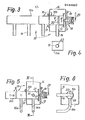
- This cleaning device 13 consists of a compressed air tank 14 and five lances 15, each with a number of flushing tubes 16 formed into an axial row.
- the number of lances 15 corresponds to the number of filter element groups 9 of the assigned filter unit 7, and the number of flushing tubes 16 of each lance 15 corresponds to the number and center distance of the number and the center distance of the filter elements 10 of the associated filter element group 9, so that - as can be seen in FIGS. 1 and 2 - in the working position of the cleaning device 13, each of its rinsing tubes 16 is axially aligned with the associated filter element 10 or its Filter hose 12 is.
- Each lance 15 is designed in two parts for assembly reasons and comprises an outer tubular lance part 15a and an inner tubular lance part 15b.
- the lance part 15a is closed at its outer end and open at its inner end and flanged to the compressed air tank 14 by means of screws 17;
- the lance part 15b of the same diameter is open at both ends and is arranged so that it projects into the compressed air tank 14 and is welded to it so that its opening facing the lance part 15a is congruent with its opening (FIGS. 3, 5).
- the lance 15 assigned to a two-row filter element group 9 located outside in the quadrant 8a to 8d has four vertically branching, straight flush pipes 16 for the first filter element row with four filter elements 10, three of which are connected to the outer lance part 15a and one to the inner lance part 15b, and for the second row of filter elements with two filter elements 10, two laterally branching, curved rinsing tubes 16a, one of which is connected to the lance part 15a and the other to the lance part 15b (FIGS. 2, 5, 6).
- the flushing pipe 16 or 16a of each lance 15 branching off from the lance part 15b within the compressed air tank is in the passage cross-section dimensioned 30% larger than the other rinsing pipes 16 and 16a.
- a control valve 18 of a known type and function is assigned to it, which is inserted into a recess in the compressed air tank 14 and fastened to the latter by screws 19.
- the pneumatically controlled via a compressed air line 20 valve plate 21 of the control valve 18 connects the associated lance 15 to the compressed air tank 14 by being lifted from the lance 15, or it separates the two from one another by being pressed on the end by spring force onto the lance.
- the compressed air tank 14 is connected in a known manner to a compressed air source via a pressure control valve.
- a blade-shaped flow guide means 22 is provided at its inflow end at the branching off of the first flushing pipe 16 or 16a, which extends approximately over the entire diameter of the lance 15 and with its convex side to the inflow end of the lance 15 or to the valve plate 21 (Fig. 4, 5).
- the flow guide means 22 is made in one piece with the first flushing pipe 16 (FIG. 3) or 16a (FIG. 5) branching off from the lance part 15b within the compressed air tank 14, in that this flushing pipe 16, 16a is diametrically divided at the upper end and one half of the pipe is notched along this length (Fig. 3).
- the flow guide means 22 of each lance 15, which is assigned to a two-row filter element group 9, has a circular segment-shaped recess 23 on its edge facing the first side branch pipe 16a branching off, which improves the inflow of compressed air into this flush pipe 16.
- each cleaning device 13 is pivotally mounted and can be folded over the cleaning device 13 opposite it on the longitudinal center plane 24, that is to say - based on FIG. 2 - the cleaning device 13 in the quadrant 8a is via the cleaning device 13 in the quadrant 8b and vice versa foldable, likewise the cleaning device 13 in the quadrant 8c via the cleaning device 13 in the quadrant 8d and vice versa (FIG. 1 - inoperative position in dash-dotted lines).
- the compressed air tank 14 of the individual cleaning device 13 has two swivel arms 25, 26 which are firmly connected to it and are each pivotably mounted on an axis 27, which in turn is received by a bearing block 28 or 29 mounted on the floor 5.
- the cleaning device 13 In the working position, the cleaning device 13 is intercepted by a support 30 fastened to the floor 5, on which it rests with the aid of a support plate 31 fastened to two of its lances 15. If a cleaning device 13 is folded by hand according to double arrow 32 into the inoperative position, it is supported with its two pivot arms 25, 26 on the compressed air tank 14 of the benac r-barten cleaning device 13, over which it is pivoted.
- a control device actuates the control valve 18 of each lance 15 one after the other via the compressed air line 20 at predetermined time intervals and this opens its valve plate 21 for a very short period of time, so that the compressed air under the pressure of 3.5 bar in the compressed air tank 14 abruptly flows to the flow guide means 22 shoots into the interior of the lance 15 and its flushing pipes 16, 16a; the compressed air flow hits the bottom of the Lance 15 and back from here; in this rebound, the flow guide means 22, due to its hollow shape, opposes the compressed air flow with a high resistance and thus prevents a significant amount of compressed air from flowing back into the compressed air tank 14 within the opening time of the valve plate 21.
- the pressure build-up which briefly builds up between the bottom of the lance 15 and its flow guide means 22 ensures that all flushing pipes 16, 16a of the lance 15 are applied approximately uniformly with compressed air and that the compressed air pulse acting on them from the filter hoses 12 of the associated filter elements 10 also in the the first or compressed air inlet side flushing tubes 16, 16a has the same thickness and thus the filter bags 12 loaded from these flushing tubes can be cleaned properly.
- the recess 23 in the flow guide 22 of each lance 15 of an external, two-row filter element group 9 ensures that the flushing burst from its two branching flushing pipes is also of the same intensity.
- the diagram according to FIG. 7 shows the flushing power of two different lances, each with six flushing tubes, plotted over the length of the lance, whereby
- curve b the rinse intensity of a lance with a rinsing tube in the area of the compressed air tank and the same diameter for all rinsing tubes (small illustration B) and curve c a lance designed according to the invention with a flow guide, a rinsing tube in the area of the compressed air tank and with a larger diameter illustrated for the first flushing pipe (small illustration C). From curve b one can see the differences in the flushing impulses in the flushing tubes of lance B, as well as the insufficient strength of the flushing impact from the first flushing tube.
- the progress achieved by the invention essentially consists in that the required filter area and filter capacity will be installed without any weakening of the tra 'constricting S äulenqueritess of the suction lifter, wherein the entire filter unit is protected from the elements enclosed by the column; Further serious advantages are the possibility of replacing the filter elements without dismantling the lances in a simple manner and in the shortest possible time, and furthermore an optimal and approximately the same flushing power for all the washing pipes of each lance of a cleaning device.
Landscapes
- Chemical & Material Sciences (AREA)
- Chemical Kinetics & Catalysis (AREA)
- Filtering Of Dispersed Particles In Gases (AREA)
- Cleaning In General (AREA)
Applications Claiming Priority (2)
| Application Number | Priority Date | Filing Date | Title |
|---|---|---|---|
| DE3443709 | 1984-11-30 | ||
| DE19843443709 DE3443709A1 (de) | 1984-11-30 | 1984-11-30 | Pneumatisches foerdergeraet mit filteranlage |
Publications (3)
| Publication Number | Publication Date |
|---|---|
| EP0184037A2 true EP0184037A2 (fr) | 1986-06-11 |
| EP0184037A3 EP0184037A3 (en) | 1988-10-05 |
| EP0184037B1 EP0184037B1 (fr) | 1992-01-02 |
Family
ID=6251574
Family Applications (1)
| Application Number | Title | Priority Date | Filing Date |
|---|---|---|---|
| EP85114413A Expired - Lifetime EP0184037B1 (fr) | 1984-11-30 | 1985-11-13 | Dispositif de transport pneumatique pourvu d'un filtre |
Country Status (2)
| Country | Link |
|---|---|
| EP (1) | EP0184037B1 (fr) |
| DE (2) | DE3443709A1 (fr) |
Families Citing this family (2)
| Publication number | Priority date | Publication date | Assignee | Title |
|---|---|---|---|---|
| JPS6393318A (ja) * | 1986-10-09 | 1988-04-23 | Tsukasa Kogyo Kk | バツグフイルタ集塵機 |
| CN105692212A (zh) * | 2016-01-28 | 2016-06-22 | 国佑实业(上海)有限公司 | 一种压缩空气的反吹方式及装置 |
Family Cites Families (11)
| Publication number | Priority date | Publication date | Assignee | Title |
|---|---|---|---|---|
| US4019641A (en) * | 1970-12-02 | 1977-04-26 | Schweizerische Aluminium Ag | Elevating and conveying system for unloading vessels or the like |
| DE2253060B2 (de) * | 1972-10-28 | 1978-09-14 | Buehler-Miag Gmbh, 3300 Braunschweig | Saugheber |
| SE391458B (sv) * | 1974-05-02 | 1977-02-21 | Svenska Flaektfabriken Ab | Sett och anordning for att rensa slangfilter med tryckpulser av rensmedium |
| US3932152A (en) * | 1974-05-08 | 1976-01-13 | U.S. Filter Corporation | Multi-stage blow-pipe construction |
| DE7720013U1 (de) * | 1977-06-25 | 1977-11-10 | Hoelter, Heinz, 4390 Gladbeck | Vorrichtung zur reinigung der filterkoerper eines gasfilters |
| US4157899A (en) * | 1977-10-11 | 1979-06-12 | Cea Carter-Day Company | Pulsed backflush air filter |
| DE2906353C3 (de) * | 1979-02-19 | 1983-02-03 | Gebrüder Bühler AG, 9240 Uzwil | Verfahren und Filtersteueranlage zur zyklischen Gegenspülung membranventilbetätigter Filterschläuche |
| DE2917052A1 (de) * | 1979-04-27 | 1980-10-30 | Kocks Gmbh Friedrich | Saugheber |
| SE418457B (sv) * | 1979-10-17 | 1981-06-09 | Bahco Ventilation Ab | Tryckluftsrensning av kring ett centrum grupperade separata filterceller |
| US4362442A (en) * | 1980-04-14 | 1982-12-07 | Dundee Cement Company | Venturi barge unloading system |
| DE3214255C2 (de) * | 1982-04-17 | 1986-01-02 | ESB Elektrostatische Sprüh- und Beschichtungsanlagen G.F. Vöhringer GmbH, 7758 Meersburg | Vorrichtung zum Abreinigen von Hohlfiltern für Pulverbeschichtungsanlagen |
-
1984
- 1984-11-30 DE DE19843443709 patent/DE3443709A1/de not_active Ceased
-
1985
- 1985-11-13 DE DE8585114413T patent/DE3585082D1/de not_active Expired - Fee Related
- 1985-11-13 EP EP85114413A patent/EP0184037B1/fr not_active Expired - Lifetime
Also Published As
| Publication number | Publication date |
|---|---|
| EP0184037B1 (fr) | 1992-01-02 |
| DE3443709A1 (de) | 1986-06-05 |
| EP0184037A3 (en) | 1988-10-05 |
| DE3585082D1 (de) | 1992-02-13 |
Similar Documents
| Publication | Publication Date | Title |
|---|---|---|
| EP0261469B1 (fr) | Appareil pour le nettoyage d'objets qui ont été en contact avec des peintures | |
| EP1122338B1 (fr) | Appareil pour projeter des liquides de décapage ou de rinçage sur des objets métalliques | |
| DE2605384C3 (de) | Flüssigkeitsfilter | |
| DE2803224C2 (de) | Selbstreinigende Filtervorrichtung | |
| DE3730438C2 (fr) | ||
| DE102005015156A1 (de) | Transportgeschirrspülmaschine und Sprührohr dafür | |
| DE2923659A1 (de) | Vorrichtung zum abzweigen von reinigungskoerpern | |
| DE4308286C2 (de) | Verfahren und Vorrichtung zum Abreinigen von mit staubförmigen Partikeln zugesetzten Filterpatronen einer Filteranlage | |
| DE69703010T2 (de) | Verfahren und Vorrichtung zur Behandlung von mit teilchenförmigem Material bestreuten, synthetischen Spielflächen | |
| EP0184037A2 (fr) | Dispositif de transport pneumatique pourvu d'un filtre | |
| DE102021104429A1 (de) | Reinigungsvorrichtung für ein industrielles Staubfilter | |
| DE102020134621A1 (de) | Reinigungsvorrichtung und Verfahren zum Betrieb einer Reinigungsvorrichtung | |
| WO2005040501A1 (fr) | Reservoir de drainage a tuyau de rinçage | |
| EP1039053B1 (fr) | Ensemble comprenant un réservoir de liquides et un dispositif pour la maintenance de la propreté du réservoir | |
| AT376582B (de) | Trommelfilter | |
| EP0552454A2 (fr) | Installation pour nettoyer les éléments filtrants d'un filtre | |
| DE19703183C2 (de) | Verteiler für Gülle | |
| DE3939645C2 (fr) | ||
| DE3300352C2 (de) | Vorrichtung zum Abziehen von Filtergranulat | |
| DE8900977U1 (de) | Vorrichtung zum Reinigen von Unterflurhydranten | |
| DE202005016872U1 (de) | Auslaufeinrichtung | |
| DE102019129605B4 (de) | Transportgeschirrspülmaschine | |
| DE102021006330A1 (de) | Reiniger | |
| EP3735322B1 (fr) | Centrifugeuse racleuse | |
| DE69700460T2 (de) | Druckluft-Filterreinigungsvorrichtung |
Legal Events
| Date | Code | Title | Description |
|---|---|---|---|
| PUAI | Public reference made under article 153(3) epc to a published international application that has entered the european phase |
Free format text: ORIGINAL CODE: 0009012 |
|
| AK | Designated contracting states |
Kind code of ref document: A2 Designated state(s): CH DE FR GB IT LI NL SE |
|
| 17P | Request for examination filed |
Effective date: 19880610 |
|
| PUAL | Search report despatched |
Free format text: ORIGINAL CODE: 0009013 |
|
| AK | Designated contracting states |
Kind code of ref document: A3 Designated state(s): CH DE FR GB IT LI NL SE |
|
| 17Q | First examination report despatched |
Effective date: 19890706 |
|
| RAP1 | Party data changed (applicant data changed or rights of an application transferred) |
Owner name: BUEHLER GMBH |
|
| ITF | It: translation for a ep patent filed | ||
| GRAA | (expected) grant |
Free format text: ORIGINAL CODE: 0009210 |
|
| AK | Designated contracting states |
Kind code of ref document: B1 Designated state(s): CH DE FR GB IT LI NL SE |
|
| GBT | Gb: translation of ep patent filed (gb section 77(6)(a)/1977) | ||
| REF | Corresponds to: |
Ref document number: 3585082 Country of ref document: DE Date of ref document: 19920213 |
|
| ET | Fr: translation filed | ||
| PLBE | No opposition filed within time limit |
Free format text: ORIGINAL CODE: 0009261 |
|
| STAA | Information on the status of an ep patent application or granted ep patent |
Free format text: STATUS: NO OPPOSITION FILED WITHIN TIME LIMIT |
|
| 26N | No opposition filed | ||
| EAL | Se: european patent in force in sweden |
Ref document number: 85114413.9 |
|
| PGFP | Annual fee paid to national office [announced via postgrant information from national office to epo] |
Ref country code: CH Payment date: 19951130 Year of fee payment: 11 |
|
| PGFP | Annual fee paid to national office [announced via postgrant information from national office to epo] |
Ref country code: GB Payment date: 19961014 Year of fee payment: 12 |
|
| PGFP | Annual fee paid to national office [announced via postgrant information from national office to epo] |
Ref country code: FR Payment date: 19961022 Year of fee payment: 12 |
|
| PGFP | Annual fee paid to national office [announced via postgrant information from national office to epo] |
Ref country code: SE Payment date: 19961024 Year of fee payment: 12 Ref country code: NL Payment date: 19961024 Year of fee payment: 12 Ref country code: DE Payment date: 19961024 Year of fee payment: 12 |
|
| PG25 | Lapsed in a contracting state [announced via postgrant information from national office to epo] |
Ref country code: LI Effective date: 19961130 Ref country code: CH Effective date: 19961130 |
|
| REG | Reference to a national code |
Ref country code: CH Ref legal event code: PL |
|
| PG25 | Lapsed in a contracting state [announced via postgrant information from national office to epo] |
Ref country code: GB Free format text: LAPSE BECAUSE OF NON-PAYMENT OF DUE FEES Effective date: 19971113 |
|
| PG25 | Lapsed in a contracting state [announced via postgrant information from national office to epo] |
Ref country code: SE Free format text: LAPSE BECAUSE OF NON-PAYMENT OF DUE FEES Effective date: 19971114 |
|
| PG25 | Lapsed in a contracting state [announced via postgrant information from national office to epo] |
Ref country code: FR Free format text: THE PATENT HAS BEEN ANNULLED BY A DECISION OF A NATIONAL AUTHORITY Effective date: 19971130 |
|
| PG25 | Lapsed in a contracting state [announced via postgrant information from national office to epo] |
Ref country code: NL Free format text: LAPSE BECAUSE OF NON-PAYMENT OF DUE FEES Effective date: 19980601 |
|
| GBPC | Gb: european patent ceased through non-payment of renewal fee |
Effective date: 19971113 |
|
| PG25 | Lapsed in a contracting state [announced via postgrant information from national office to epo] |
Ref country code: DE Free format text: LAPSE BECAUSE OF NON-PAYMENT OF DUE FEES Effective date: 19980801 |
|
| EUG | Se: european patent has lapsed |
Ref document number: 85114413.9 |
|
| NLV4 | Nl: lapsed or anulled due to non-payment of the annual fee |
Effective date: 19980601 |
|
| REG | Reference to a national code |
Ref country code: FR Ref legal event code: ST |