EP0184070A2 - Stöpselrohr für den Kryostaten eines Kernresonanzmagneten - Google Patents
Stöpselrohr für den Kryostaten eines Kernresonanzmagneten Download PDFInfo
- Publication number
- EP0184070A2 EP0184070A2 EP85114728A EP85114728A EP0184070A2 EP 0184070 A2 EP0184070 A2 EP 0184070A2 EP 85114728 A EP85114728 A EP 85114728A EP 85114728 A EP85114728 A EP 85114728A EP 0184070 A2 EP0184070 A2 EP 0184070A2
- Authority
- EP
- European Patent Office
- Prior art keywords
- plug tube
- cryostat
- tube
- springs
- ring
- Prior art date
- Legal status (The legal status is an assumption and is not a legal conclusion. Google has not performed a legal analysis and makes no representation as to the accuracy of the status listed.)
- Withdrawn
Links
- 230000035515 penetration Effects 0.000 claims abstract description 34
- 230000013011 mating Effects 0.000 claims abstract description 3
- 238000005304 joining Methods 0.000 claims description 18
- 239000000463 material Substances 0.000 claims description 17
- 238000005219 brazing Methods 0.000 claims description 4
- 229910000906 Bronze Inorganic materials 0.000 claims description 2
- RYGMFSIKBFXOCR-UHFFFAOYSA-N Copper Chemical compound [Cu] RYGMFSIKBFXOCR-UHFFFAOYSA-N 0.000 claims description 2
- OAICVXFJPJFONN-UHFFFAOYSA-N Phosphorus Chemical compound [P] OAICVXFJPJFONN-UHFFFAOYSA-N 0.000 claims description 2
- DMFGNRRURHSENX-UHFFFAOYSA-N beryllium copper Chemical compound [Be].[Cu] DMFGNRRURHSENX-UHFFFAOYSA-N 0.000 claims description 2
- 239000010974 bronze Substances 0.000 claims description 2
- 239000002131 composite material Substances 0.000 claims description 2
- 229910052802 copper Inorganic materials 0.000 claims description 2
- 239000010949 copper Substances 0.000 claims description 2
- KUNSUQLRTQLHQQ-UHFFFAOYSA-N copper tin Chemical compound [Cu].[Sn] KUNSUQLRTQLHQQ-UHFFFAOYSA-N 0.000 claims description 2
- 239000003365 glass fiber Substances 0.000 claims description 2
- 229910001220 stainless steel Inorganic materials 0.000 claims description 2
- 239000010935 stainless steel Substances 0.000 claims description 2
- 238000012546 transfer Methods 0.000 abstract description 14
- 239000002826 coolant Substances 0.000 abstract description 10
- 238000005057 refrigeration Methods 0.000 abstract description 4
- 238000010348 incorporation Methods 0.000 abstract description 2
- 238000002059 diagnostic imaging Methods 0.000 abstract 1
- 239000001307 helium Substances 0.000 description 13
- 229910052734 helium Inorganic materials 0.000 description 13
- SWQJXJOGLNCZEY-UHFFFAOYSA-N helium atom Chemical compound [He] SWQJXJOGLNCZEY-UHFFFAOYSA-N 0.000 description 13
- 238000003780 insertion Methods 0.000 description 7
- 230000037431 insertion Effects 0.000 description 7
- 238000005481 NMR spectroscopy Methods 0.000 description 6
- 238000010276 construction Methods 0.000 description 5
- 239000007788 liquid Substances 0.000 description 4
- 239000007789 gas Substances 0.000 description 3
- 238000013023 gasketing Methods 0.000 description 3
- 238000003384 imaging method Methods 0.000 description 3
- 238000000034 method Methods 0.000 description 3
- 230000004323 axial length Effects 0.000 description 2
- 238000013461 design Methods 0.000 description 2
- 238000004519 manufacturing process Methods 0.000 description 2
- 238000012986 modification Methods 0.000 description 2
- 230000004048 modification Effects 0.000 description 2
- 238000005476 soldering Methods 0.000 description 2
- 239000004593 Epoxy Substances 0.000 description 1
- 239000000853 adhesive Substances 0.000 description 1
- 230000001070 adhesive effect Effects 0.000 description 1
- 230000002411 adverse Effects 0.000 description 1
- 238000004458 analytical method Methods 0.000 description 1
- 238000000137 annealing Methods 0.000 description 1
- 230000003416 augmentation Effects 0.000 description 1
- 238000012937 correction Methods 0.000 description 1
- 238000005336 cracking Methods 0.000 description 1
- 230000003247 decreasing effect Effects 0.000 description 1
- 230000001747 exhibiting effect Effects 0.000 description 1
- 238000009413 insulation Methods 0.000 description 1
- 230000002452 interceptive effect Effects 0.000 description 1
- 230000007246 mechanism Effects 0.000 description 1
- 229910052751 metal Inorganic materials 0.000 description 1
- 239000002184 metal Substances 0.000 description 1
- 230000008520 organization Effects 0.000 description 1
- 230000000135 prohibitive effect Effects 0.000 description 1
- 230000009467 reduction Effects 0.000 description 1
- 238000007789 sealing Methods 0.000 description 1
- 239000007787 solid Substances 0.000 description 1
- 238000003466 welding Methods 0.000 description 1
Images

Classifications
-
- F—MECHANICAL ENGINEERING; LIGHTING; HEATING; WEAPONS; BLASTING
- F25—REFRIGERATION OR COOLING; COMBINED HEATING AND REFRIGERATION SYSTEMS; HEAT PUMP SYSTEMS; MANUFACTURE OR STORAGE OF ICE; LIQUEFACTION SOLIDIFICATION OF GASES
- F25D—REFRIGERATORS; COLD ROOMS; ICE-BOXES; COOLING OR FREEZING APPARATUS NOT OTHERWISE PROVIDED FOR
- F25D19/00—Arrangement or mounting of refrigeration units with respect to devices or objects to be refrigerated, e.g. infrared detectors
- F25D19/006—Thermal coupling structure or interface
-
- F—MECHANICAL ENGINEERING; LIGHTING; HEATING; WEAPONS; BLASTING
- F17—STORING OR DISTRIBUTING GASES OR LIQUIDS
- F17C—VESSELS FOR CONTAINING OR STORING COMPRESSED, LIQUEFIED OR SOLIDIFIED GASES; FIXED-CAPACITY GAS-HOLDERS; FILLING VESSELS WITH, OR DISCHARGING FROM VESSELS, COMPRESSED, LIQUEFIED, OR SOLIDIFIED GASES
- F17C3/00—Vessels not under pressure
- F17C3/02—Vessels not under pressure with provision for thermal insulation
- F17C3/08—Vessels not under pressure with provision for thermal insulation by vacuum spaces, e.g. Dewar flask
- F17C3/085—Cryostats
-
- F—MECHANICAL ENGINEERING; LIGHTING; HEATING; WEAPONS; BLASTING
- F17—STORING OR DISTRIBUTING GASES OR LIQUIDS
- F17C—VESSELS FOR CONTAINING OR STORING COMPRESSED, LIQUEFIED OR SOLIDIFIED GASES; FIXED-CAPACITY GAS-HOLDERS; FILLING VESSELS WITH, OR DISCHARGING FROM VESSELS, COMPRESSED, LIQUEFIED, OR SOLIDIFIED GASES
- F17C2203/00—Vessel construction, in particular walls or details thereof
- F17C2203/06—Materials for walls or layers thereof; Properties or structures of walls or their materials
- F17C2203/068—Special properties of materials for vessel walls
- F17C2203/0687—Special properties of materials for vessel walls superconducting
-
- F—MECHANICAL ENGINEERING; LIGHTING; HEATING; WEAPONS; BLASTING
- F17—STORING OR DISTRIBUTING GASES OR LIQUIDS
- F17C—VESSELS FOR CONTAINING OR STORING COMPRESSED, LIQUEFIED OR SOLIDIFIED GASES; FIXED-CAPACITY GAS-HOLDERS; FILLING VESSELS WITH, OR DISCHARGING FROM VESSELS, COMPRESSED, LIQUEFIED, OR SOLIDIFIED GASES
- F17C2221/00—Handled fluid, in particular type of fluid
- F17C2221/01—Pure fluids
- F17C2221/016—Noble gases (Ar, Kr, Xe)
- F17C2221/017—Helium
-
- F—MECHANICAL ENGINEERING; LIGHTING; HEATING; WEAPONS; BLASTING
- F17—STORING OR DISTRIBUTING GASES OR LIQUIDS
- F17C—VESSELS FOR CONTAINING OR STORING COMPRESSED, LIQUEFIED OR SOLIDIFIED GASES; FIXED-CAPACITY GAS-HOLDERS; FILLING VESSELS WITH, OR DISCHARGING FROM VESSELS, COMPRESSED, LIQUEFIED, OR SOLIDIFIED GASES
- F17C2270/00—Applications
- F17C2270/05—Applications for industrial use
- F17C2270/0527—Superconductors
- F17C2270/0536—Magnetic resonance imaging
-
- G—PHYSICS
- G01—MEASURING; TESTING
- G01R—MEASURING ELECTRIC VARIABLES; MEASURING MAGNETIC VARIABLES
- G01R33/00—Arrangements or instruments for measuring magnetic variables
- G01R33/20—Arrangements or instruments for measuring magnetic variables involving magnetic resonance
- G01R33/28—Details of apparatus provided for in groups G01R33/44 - G01R33/64
- G01R33/38—Systems for generation, homogenisation or stabilisation of the main or gradient magnetic field
- G01R33/3804—Additional hardware for cooling or heating of the magnet assembly, for housing a cooled or heated part of the magnet assembly or for temperature control of the magnet assembly
-
- H—ELECTRICITY
- H01—ELECTRIC ELEMENTS
- H01F—MAGNETS; INDUCTANCES; TRANSFORMERS; SELECTION OF MATERIALS FOR THEIR MAGNETIC PROPERTIES
- H01F6/00—Superconducting magnets; Superconducting coils
- H01F6/04—Cooling
Definitions
- the present invention is generally directed to horizontal penetrations extending between the inner and outer walls of a cryostat, particularly a cryostat employing liquid helium as a coolant material. More particularly the present invention is directed to a plug tube employing heat transfer contacts to provide a refrigeration interface for a nuclear magnetic resonance (NMR) magnet cryostat.
- NMR nuclear magnetic resonance
- cryostat In the generation of medical diagnostic images in NMR imaging, it is necessary to provide a temporally stable and spacially homogeneous magnetic field.
- the use of superconductive electrical materials maintained at cryogenic temperatures provides advantageous means to produce such a field.
- a cryostat is employed.
- a cryostat contains an innermost chamber in which liquid helium, for example, is employed to cool the superconductive magnet materials.
- the cryostat itself, typically comprises a toroidal structure with other nested toroidal structures inside the exterior vessel to provide the desired vacuum conditions and thermal shielding. Since it is necessary to provide electrical energy to the main magnet coil, to various correction coils and to various gradient coils employed in NMR imaging, it is necessary that there be at least one penetration through the cryostat vessel walls.
- Typical prior art penetrations have been vertical. While the apparatus of the present invention is particularly directed to non-vertical penetrations, it is also applicable to vertical ones. However, vertical penetrations have produced undesirable problems of alignment and assembly from a manufacturing viewpoint. Horizontal cryostat penetrations have, however, not been employed for reasons of thermal efficiency. In particular, it is seen that for a coolant such as liquid helium, there is a large dependency of gaseous or vapor density upon temperature. Accordingly, helium vapor found within a vertical penetration is naturally disposed in a layered configuration as a result of the density variation from the bottom to the top of the penetration. This layering provides a natural form of thermal insulation along the length of a vertical penetration.
- a coolant such as liquid helium
- the temperature profile is substantially constant.
- any layering that would exist would not be in the direction of the long axis of the cryostat penetration, that'is, in the direction of the temperature gradient.
- the temperature gradient along the penetration would tend to set up free convection currents in the vapor within the penetration. This would result in a much more rapid loss of coolant than is desired. Since the cost of helium is relatively high, it is seen that this loss of coolant is undesirable.
- cryostat plugs for horizontal penetrations have been designed so as to include special plug tubes with spiral grooves. These spiral grooves have been provided in a thin walled removable plug tube structure which is inserted into the cryostat penetration. Gasket material is disposed in the grooves so that a helical helium vapor path is provided along the axial length of the penetration with helium vapor flowing in the annular space defined between the plug tube and the cryostat penetration wall.
- This annular space must be closely controlled since the speed of helium vapor within the space determines in part the rate of heat loss from the cryostat. This annular space is typically about 1/100 of an inch wide.
- the spiral gas path for vaporized helium counteracts the natural convection currents that would otherwise be established in the annular volume.
- thermal energy from certain cryostat vessel walls to the exterior environment. This is desired both for refrigerating various cryostat shields and also in those situations in which an exterior helium liquefier is provided to recycle helium vapor which is boiled off from the interior cryostat vessel or vessels. For example, it is desired to transfer between about 1 and 2 watts of thermal energy at an intermediate shield location which is maintained at a temperature of between about 10°K and about 50°K. Additionally, it is desirable to be able to transfer between about 5 and about 10 watts of thermal energy at a more exterior shield which is maintained at a temperature of between about 50°K and about 100°K.
- the annular gap represents too large a thermal resistance for effective heat transfer.
- the size of this gap and the relatively thin walled nature of the plug tube provides stringent limitations upon the size, strength and construction of any device that might be employed to improve local heat transfer conditions at the shield locations without adversely affecting either the size of the gap, strength of the tube or other thermal conditions.
- the spiral gasketing material in the plug tube prevents any heat transfer augmentation device to be placed on a penetration tube wall where it would interfere with insertion of the plug.
- air must be prevented from entering a penetration tube since there would be a tendency to form liquid or solid air condensate.
- a retractable disk or cylinder which slides in and out of a penetration tube is added to prevent entry of air after plug retraction.
- the retractable disk or cylinder generally requires a constant cross section tube in all practical construction designs.
- a means is to be provided for localized thermal transfer across a high thermal resistance gap, typically filled with coolant vapors such as helium.
- the thermal transfer is to be localized at specific shield locations and cannot interfere with the insertion or removal of a plug tube partially defining the gap nor with the spiral flow of coolant vapor in the gap.
- the desired thermal transfer structure must not interfere with the spiral gasketing material and must not interfere with the insertion and removal of the plug tube.
- the thermal transfer means desired is to be employed in an extremely thin walled structure (15 to 25 mils) having significant length (approximately 14 inches) with respect to its diameter (approximately 3.5" in practice).
- a plug tube for a crycstat comprises at least two thin walled cylindrical conduit sections joined together by at least one ring disposed on the interior of the conduits so as to provide at least one circumferential groove for the disposition of a plurality of substantially U-shaped springs disposed within the grooves so that a long side of each spring is in thermal contact with the ring.
- This structure provides a mechanism which provides an adequate groove depth for the disposition of the thermal contact springs. This depth cannot be provided in the thin walled vent tube itself because of its thin walled nature. Additionally, the thermal contact springs must exhibit a certain width to prevent fracture and cracking at a small radius bend which would otherwise be required.
- the thermal contact springs are preferably provided in the form of a single strip of finger-like springs which are disposed directly in the groove formed by the conduit sections and the joining ring.
- the circumferential groove may be made wide enough for a plurality of spring strips. Additionally, in general, circumferential grooves and spring strips are provided wherever thermal contact is needed between the plug tube body and a corresponding cryostat location.
- FIG 1 illustrates a preferred embodiment of the present invention.
- plug tube 10 with spiral grooves 15 and a pair of thermal contact springs 20 and 30 disposed within a circumferential groove.
- Plug tube 10 is disposed within plenum cap 13.
- Plenum cap 13 includes a channel with 0-ring 12 for sealing against a mating cryostat portion.
- vapor gap 11 which exists between plug tube 10 and the visible portion of cap 13.
- plug tube 10 is affixed to the interior bottom portion of plenum cap 13. Coolant vapor flows in a helical path around the circumference of plug tube 10 in paths that are defined by gasketing material (not shown) employed in grooves 15, between plug tube 10 and the inner wall of cryostat penetration tube 40 (see Figure 3).
- Coolant vapor passes through gap 11 into plenum cap 13 and eventually exits from plenum aperture 14. In one embodiment of the present invention this vapor may be reliquefied and reintroduced into the cryostat. In this situation, the vent tube of the present invention provides an appropriate interface between the cryostat and external refrigeration and/or liquefaction equipment. It is also observed in Figure 1 that the pitch of the spiral grooves varies along the tube axis. This pitch variation assists in preserving the desired axial temperature gradients along the plug tube.
- Figure 1 illustrates the presence of thermal spring contact sets 20 and 30. These spring sets are disposed in circumferential grooves in vent tube 10. However, because of the extremely thin walled nature of plug tube 10 (approximately 20 mils in thickness) and because of the depth requirements for the spring material, the grooves in which the thermal contacts are disposed actually extend entirely through plug tube 10 so that plug tube 10 actually subsists in a plurality of coaxially disposed, cylindrical conduit sections. The sections of conduit are therefore actually held together by means of at least one underlying ring which supports the conduit sections and one or more spring strips.
- Figure 2 provides a detailed view of this structure which is shown in even more detail in Figure 3. In particular, in Figure 2, spring contact set 30 is seen to be disposed in thermal contact with underlying joining ring 33.
- Figure 3 also illustrates an alternate embodiment of the present invention in which a pair of spring strips is disposed in the same circumferential groove.
- single spring strips have been found to be preferred because of their simpler structure.
- plug tube 10 is first provided with a set of spirally disposed grooves 15 extending approximately half way through the tube material. Such grooves do not significantly weaken the strength of plug tube 10.
- a circumferential groove in plug tube 10 of the desired.depth would extend most if not all of the way through the vent tube itself.
- plug tube 10 is provided with a coaxially disposed joining ring 33 which is affixed to the inside of plug tube 10 at the desired location for the circumferential groove or grooves.
- Joining ring 33 is then affixed to plug tube 10 by any convenient means such as by brazing, welding, or the use of adhesive materials.
- Joining ring 33 With joining ring 33 in place a circumferential groove of appropriate depth is machined into plug tube 10, and also preferably at least partially into joining ring 33.
- Spring strips 20 and 30 are then disposed in their respective circumferential grooves and their ends attached so as to hold the strips in place.
- This joining is typically accomplished by soldering the common portion of the spring strip within the channel. Soldering is preferred so as to avoid annealing the spring strip material as a result of the high temperatures of brazing.
- Figure 3 illustrates joining ring 33 connecting a lower section of plug tube 10 to an upper section of plug tube 10. Brazed joints, added after the construction described above, are illustrated. Plug tube 10 is also seen disposed in its operative position within the cryostat and in particular within cryostat penetration tube 40. Spiral groove 15 is also visible in this view. Also visible are spring strips 30a and 30b. Each of these spring strips possesses common portion 32 which is in thermal contact with joining ring 33. Additicnally, U-shaped spring members 31 are disposed so as to be in thermal contact with wall 40, which is in turn in thermal contact with internal cryostat shields 50.
- shield 50 may be disposed at a temperature of between about 50°K and 100°K. Accordingly, the desired thermal contact is provided across a gap which otherwise exhibits a high degree of thermal resistance, both because of its size and because of the vapor flowing therein. Additionally, it is seen that the thermal contact springs of the present invention do not in any way interfere with the flow of helium vapor along the defined helical path. It is also seen that the springs preferably possess bend 34 which facilitates their insertion and removal from the cryostat penetration.
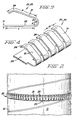
- FIG. 4 provides a detailed illustration of a portion of a spring set employable in the present invention.
- a set of U-shaped springs in an integral strip structure wherein one side of the U-shaped springs comprises an integral structure 32.
- Individual spring elements 31, each having a width W of between approximately 25 and 50 mils, are also seen to include a slight bend to facilitate insertion and removal of the penetration assembly.
- the thickness H of the strip material is typically between approximately 6 and 12 mils.
- the strip extends for a distance L along the joining ring. L is between about typically 1/8 and 1/4 inches.
- the length of the other side of the U-shaped spring contact is labeled D and is typically approximately the same length as L.
- R represents the radius of the U-bend and 6 represents the angle subtended by the bend. In general R is between approximately 15 and 25 mils and 8 is between approximately 165° and 170°.
- tube or conduit 10 preferably comprises a material such as stainless steel.
- Joining ring 33 typically comprises a thermally conductive metal such as copper.
- the springs themselves preferably comprise a material such as beryllium copper or phosphor bronze. In general, joining ring 33 is affixed to the conduit sections by brazing. The springs deflect upon insertion to provide desired normal contact forces between tube 10 and wall 40. Since multiple prong type springs are preferred in the present invention to accommodate the curvature of the cryostat penetration wall, only a fraction of the total contact area is available. However, the gaps in the spring sets provide the required path for the continuation of the spiral gas flow.
- the plug tube of the present invention provides a desirable solution to the problems encountered.
- excellent thermal contact is maintained without any interruption in the spiral flow path.
- Means are provided, principally through the incorporation of a joining ring to meet the requirements dictated by the small thickness of the plug tube itself.
- plug tube plugs may be manufactured with the desired circumferential gap in various selected positions depending upon the cryostat geometry, and in particular upon the location of internal cryostat shield structures.
- the plug tube of the present invention is therefore seen to facilitate the interfacing of the internal cryostat environment with external refrigeration and liquefaction equipment as desired.
- the apparatus of the present invention is seen to meet all of the constraints imposed by the small size of the annular gap, limitations imposed by the material constraints and limitations imposed by the thermodynamics of cryostat design.
Landscapes
- Engineering & Computer Science (AREA)
- Physics & Mathematics (AREA)
- Thermal Sciences (AREA)
- Mechanical Engineering (AREA)
- General Engineering & Computer Science (AREA)
- Chemical & Material Sciences (AREA)
- Combustion & Propulsion (AREA)
- Magnetic Resonance Imaging Apparatus (AREA)
- Containers, Films, And Cooling For Superconductive Devices (AREA)
Applications Claiming Priority (2)
| Application Number | Priority Date | Filing Date | Title |
|---|---|---|---|
| US06/676,368 US4562703A (en) | 1984-11-29 | 1984-11-29 | Plug tube for NMR magnet cryostat |
| US676368 | 2003-09-30 |
Publications (2)
| Publication Number | Publication Date |
|---|---|
| EP0184070A2 true EP0184070A2 (de) | 1986-06-11 |
| EP0184070A3 EP0184070A3 (de) | 1986-10-01 |
Family
ID=24714224
Family Applications (1)
| Application Number | Title | Priority Date | Filing Date |
|---|---|---|---|
| EP19850114728 Withdrawn EP0184070A3 (de) | 1984-11-29 | 1985-11-19 | Stöpselrohr für den Kryostaten eines Kernresonanzmagneten |
Country Status (5)
| Country | Link |
|---|---|
| US (1) | US4562703A (de) |
| EP (1) | EP0184070A3 (de) |
| JP (1) | JPS61153553A (de) |
| CA (1) | CA1271987A (de) |
| IL (1) | IL76811A0 (de) |
Cited By (1)
| Publication number | Priority date | Publication date | Assignee | Title |
|---|---|---|---|---|
| FR2613046A1 (fr) * | 1987-03-23 | 1988-09-30 | Abg Semca | Refroidisseur cryogenique |
Families Citing this family (12)
| Publication number | Priority date | Publication date | Assignee | Title |
|---|---|---|---|---|
| US4635451A (en) * | 1986-02-04 | 1987-01-13 | General Electric Company | Spring loaded valve for adding cryogenic liquid to a cryostat |
| US4633682A (en) * | 1986-02-04 | 1987-01-06 | General Electric Company | Horizontal cryostat insert with a vertical service stack |
| US4635450A (en) * | 1986-02-04 | 1987-01-13 | General Electric Company | Compact retractable cryogenic leads |
| US4667487A (en) * | 1986-05-05 | 1987-05-26 | General Electric Company | Refrigerated penetration insert for cryostat with rotating thermal disconnect |
| US4667486A (en) * | 1986-05-05 | 1987-05-26 | General Electric Company | Refrigerated penetration insert for cryostat with axial thermal disconnect |
| DE3907528A1 (de) * | 1989-03-08 | 1990-09-20 | Siemens Ag | Einrichtung zur verbindung zweier aneinanderfuegbarer teile mit unterschiedlichem dehnungsverhalten |
| DE3908842A1 (de) * | 1989-03-17 | 1990-09-20 | Siemens Ag | Einrichtung mit einer thermisch loesbaren verbindung zwischen zwei teilen mit unterschiedlichem dehnungsverhalten |
| US5657634A (en) * | 1995-12-29 | 1997-08-19 | General Electric Company | Convection cooling of bellows convolutions using sleeve penetration tube |
| US6804965B2 (en) * | 2003-02-12 | 2004-10-19 | Applied Integrated Systems, Inc. | Heat exchanger for high purity and corrosive fluids |
| JP5746626B2 (ja) * | 2008-09-09 | 2015-07-08 | コーニンクレッカ フィリップス エヌ ヴェ | 極低温再液化冷凍機用の水平フィンによる熱交換器 |
| FR3005040A1 (fr) * | 2013-04-30 | 2014-10-31 | Inguran Llc Dba Sexing Technologies | Dispositif de transport et/ou de stockage comprenant une ampoule isolante a double paroi |
| US11774187B2 (en) * | 2018-04-19 | 2023-10-03 | Kyungdong Navien Co., Ltd. | Heat transfer fin of fin-tube type heat exchanger |
Family Cites Families (12)
| Publication number | Priority date | Publication date | Assignee | Title |
|---|---|---|---|---|
| US3187082A (en) * | 1961-02-01 | 1965-06-01 | Cool Fin Electronics Corp | Heat dissipating electrical shield |
| US3193610A (en) * | 1962-08-10 | 1965-07-06 | Atlee Corp | Shields for vacuum tubes and the like |
| US3377813A (en) * | 1965-10-22 | 1968-04-16 | Cryogenic Eng Co | Storage container |
| US3483709A (en) * | 1967-07-21 | 1969-12-16 | Princeton Gamma Tech Inc | Low temperature system |
| US3894403A (en) * | 1973-06-08 | 1975-07-15 | Air Prod & Chem | Vibration-free refrigeration transfer |
| FR2345658A1 (fr) * | 1976-03-25 | 1977-10-21 | Air Liquide | Reservoir pour liquide cryogenique |
| DE2806787A1 (de) * | 1978-02-17 | 1979-08-23 | Linde Ag | Behaelter fuer tiefkalte verfluessigte gase |
| US4223540A (en) * | 1979-03-02 | 1980-09-23 | Air Products And Chemicals, Inc. | Dewar and removable refrigerator for maintaining liquefied gas inventory |
| US4279127A (en) * | 1979-03-02 | 1981-07-21 | Air Products And Chemicals, Inc. | Removable refrigerator for maintaining liquefied gas inventory |
| US4277949A (en) * | 1979-06-22 | 1981-07-14 | Air Products And Chemicals, Inc. | Cryostat with serviceable refrigerator |
| US4344302A (en) * | 1981-06-08 | 1982-08-17 | Hughes Aircraft Company | Thermal coupling structure for cryogenic refrigeration |
| US4535596A (en) * | 1984-03-30 | 1985-08-20 | General Electric Company | Plug for horizontal cryostat penetration |
-
1984
- 1984-11-29 US US06/676,368 patent/US4562703A/en not_active Expired - Fee Related
-
1985
- 1985-10-24 IL IL76811A patent/IL76811A0/xx unknown
- 1985-11-19 EP EP19850114728 patent/EP0184070A3/de not_active Withdrawn
- 1985-11-28 JP JP60266297A patent/JPS61153553A/ja active Pending
- 1985-11-29 CA CA000496575A patent/CA1271987A/en not_active Expired
Cited By (2)
| Publication number | Priority date | Publication date | Assignee | Title |
|---|---|---|---|---|
| FR2613046A1 (fr) * | 1987-03-23 | 1988-09-30 | Abg Semca | Refroidisseur cryogenique |
| EP0285491A1 (de) * | 1987-03-23 | 1988-10-05 | Abg Semca S.A. | Tiefsttemperaturkälteanlage |
Also Published As
| Publication number | Publication date |
|---|---|
| JPS61153553A (ja) | 1986-07-12 |
| US4562703A (en) | 1986-01-07 |
| CA1271987A (en) | 1990-07-24 |
| IL76811A0 (en) | 1986-02-28 |
| EP0184070A3 (de) | 1986-10-01 |
Similar Documents
| Publication | Publication Date | Title |
|---|---|---|
| US4562703A (en) | Plug tube for NMR magnet cryostat | |
| EP0773565B1 (de) | Offener kryogengekühlter supraleitender Magnet für die Bilderzeugung durch magnetische Resonanz | |
| US4516404A (en) | Foam filled insert for horizontal cryostat penetrations | |
| US5782095A (en) | Cryogen recondensing superconducting magnet | |
| US4535596A (en) | Plug for horizontal cryostat penetration | |
| US6995562B2 (en) | Conduction cooled passively-shielded MRI magnet | |
| EP0350262B1 (de) | Stützvorrichtung einer Strahlungsabschirmung in einem Magnetresonanz-Magneten | |
| US8228147B2 (en) | Supported superconducting magnet | |
| US7287387B2 (en) | Cooling apparatus | |
| EP0781956B1 (de) | Konvektionskühlung von Balgkonvolutionen unter Verwendung von einem Durchdringungsrohr mit Muffe | |
| US4522034A (en) | Horizontal cryostat penetration insert and assembly | |
| US20150332830A1 (en) | Apparatus for thermal shielding of a superconducting magnet | |
| US5381122A (en) | Open MRI magnet having a support structure | |
| EP0135185A2 (de) | Kryostat für die magnetische Kernresonanz | |
| US7131276B2 (en) | Pulse tube refrigerator | |
| US5568104A (en) | Open MRI superconductive magnet with cryogenic-fluid cooling | |
| US5225782A (en) | Eddy current free MRI magnet with integrated gradient coils | |
| CN102809239A (zh) | 用于减小低温恒温器热负荷的穿透管组件 | |
| US3781733A (en) | Low heat conductant temperature stabilized structural support | |
| US4622824A (en) | Cryostat suspension system | |
| US4633682A (en) | Horizontal cryostat insert with a vertical service stack | |
| GB2491464A (en) | Penetration tube assemblies for reducing cryostat heat load | |
| US20080271467A1 (en) | Refrigerator Interface for Cryostat | |
| EP0150562B1 (de) | Distanzbüchsensystem für Kryostatgefässwände | |
| JPH08321418A (ja) | Mriシステムで使用するための超電導電磁石 |
Legal Events
| Date | Code | Title | Description |
|---|---|---|---|
| PUAI | Public reference made under article 153(3) epc to a published international application that has entered the european phase |
Free format text: ORIGINAL CODE: 0009012 |
|
| AK | Designated contracting states |
Kind code of ref document: A2 Designated state(s): CH DE FR GB IT LI NL SE |
|
| PUAL | Search report despatched |
Free format text: ORIGINAL CODE: 0009013 |
|
| AK | Designated contracting states |
Kind code of ref document: A3 Designated state(s): CH DE FR GB IT LI NL SE |
|
| 17P | Request for examination filed |
Effective date: 19870319 |
|
| STAA | Information on the status of an ep patent application or granted ep patent |
Free format text: STATUS: THE APPLICATION HAS BEEN WITHDRAWN |
|
| 18W | Application withdrawn |
Withdrawal date: 19870505 |
|
| RIN1 | Information on inventor provided before grant (corrected) |
Inventor name: PRICE, THOMAS EARLEST Inventor name: MILLER, RUSSEL SCOTT |