EP0184088A2 - Expertsystem - Google Patents
Expertsystem Download PDFInfo
- Publication number
- EP0184088A2 EP0184088A2 EP85114860A EP85114860A EP0184088A2 EP 0184088 A2 EP0184088 A2 EP 0184088A2 EP 85114860 A EP85114860 A EP 85114860A EP 85114860 A EP85114860 A EP 85114860A EP 0184088 A2 EP0184088 A2 EP 0184088A2
- Authority
- EP
- European Patent Office
- Prior art keywords
- query
- rules
- subject matter
- expert system
- rule
- Prior art date
- Legal status (The legal status is an assumption and is not a legal conclusion. Google has not performed a legal analysis and makes no representation as to the accuracy of the status listed.)
- Withdrawn
Links
Images


Classifications
-
- G—PHYSICS
- G06—COMPUTING OR CALCULATING; COUNTING
- G06F—ELECTRIC DIGITAL DATA PROCESSING
- G06F11/00—Error detection; Error correction; Monitoring
- G06F11/22—Detection or location of defective computer hardware by testing during standby operation or during idle time, e.g. start-up testing
- G06F11/2257—Detection or location of defective computer hardware by testing during standby operation or during idle time, e.g. start-up testing using expert systems
-
- G—PHYSICS
- G06—COMPUTING OR CALCULATING; COUNTING
- G06N—COMPUTING ARRANGEMENTS BASED ON SPECIFIC COMPUTATIONAL MODELS
- G06N5/00—Computing arrangements using knowledge-based models
- G06N5/04—Inference or reasoning models
Definitions
- the present invention relates to expert systems and particularly to a method and apparatus for providing trouble shooting assistance.
- Expert systems as heretofore available have employed a technique known as knowledge engineering to formulate groups of rules for the solution of problems.
- the rules may be presented to the user by means of a series of questions which require observation by the user and the input by the user of answers to the questions.
- the expert system will thereupon supply the user with a conclusion or conclusions in accordance with the set of rules.
- Expert systems have heretofore been employed in fields such as medical diagnosis for logically indicating a patient's status in accordance with a large number of observations.
- the rules comprising the expert system are typically constructed by so- called knowledge engineers who interview experts in the field in order to derive the body of rules which captures the required expertise.
- An advantageous application for an expert system would be for trouble shooting and repair of apparatus such as electronic circuitry wherein a set of rules, answered properly, could diagnose a particular problem or failure encountered.
- apparatus such as electronic circuitry
- a set of rules, answered properly could diagnose a particular problem or failure encountered.
- the expert system should be able to guide the technician easily through a diagnostic and repair procedure even though the technician is only marginally familiar with the equipment and the manner in which it really operates. The expert system would then replace or minimize constant supervision by more knowledgeable technical personnel.
- a method and apparatus for providing expert information consecutively presents rules including queries to the user, wherein the queries are directed toward parts or portions of the particular subject matter with respect to which a problem has been encountered.
- the user is also provided with a visual representation comprising a diagram or drawing of the subject matter, with graphic identification of the part or portion to which the query is directed.
- the query directs measurement of a voltage between a pair of points
- probe icons are displayed on the diagram at the points where the measurement is to be taken.
- the associated query may ask the technician to make the measurement on the real apparatus and indicate whether the voltage is greater than or less than a predetermined value.
- the technician then inputs the answer, causing the expert system to either reach a conclusion or present a further query or rule in logical sequence. If a conclusion is reached that a particular part or component is faulty, then such component or part is graphically identified on the drawing so as to guide the technician in corrective measures to be taken.
- the expert system is implemented on an artificial intelligence system or work station such as a Tektronix 4404AI or a Xerox 1100 or 1132 workstation.
- an artificial intelligence system or work station such as a Tektronix 4404AI or a Xerox 1100 or 1132 workstation.
- Such a system is illustrated enerally in FIG. 1 and includes a programmed processor 10 having associated therewith a memory 12 accessible by the processor and a display means or monitor 14 including a cathode ray tube. Also provided are a keyboard 11 and a mouse 13.
- a typical display generated on the display means is illustrated
- FIG. 2 In the present example of the expert system, a troubleshooting assistant for a Tektronix type FG 502 function generator is disclosed, but it is understood the expert system according to the present invention comprehends a trouble shooting assistant for any type of apparatus, or alternatively an assistant for solving problems with respect to other subject matter for which a set of rules may be formulated. Rule formulation is more particularly described in a subsequent portion of this application.
- the expert system is provided with a bitmapped display, i.e. the memory 12 includes bit maps capable of supplying a diagrammatic representation of particular subject matter on display means 14.
- the diagrammatic representation comprises schematic and circuit board diagrams of the aforementioned FG 502 function generator (triangle generator section).
- the bitmapped display supplies a drawing 16 of the circuit board, a corresponding circuit schematic diagram 18, and is further provided with three windows 20, 22 and 24. Each component and significant node in a diagram is stored as an "object" programmed in SMALLTALK.
- Each SMALLTALK object contains as part of the data structure the coordinates of a bounding box in the diagram including the object of interest, or in the case of a node, of the point representing that node in the diagram.
- a collection of icons for example probe icons 26 and 28 in FIG. 2, are stored as SMALLTALK objects of the type "icon instance".
- SMALLTALK objects of the form "icon instance” can accept a message which causes the icons to be displayed at a particular location on the diagrams.
- SMALLTALK objects of the form "icon instance” may also accept a message which causes the icon to be visibly moved across the screen from one known location to another.
- a rule processor part of the expert system program processes rules which request individual actions of the type display or translate, and dispatches the request to whichever icon is appropriate.
- a display icon representing a probe may be displayed at the location where a measurement is to be performed.
- the diagram display region containing the object to be removed may be blanked out and a moveable icon may also be constructed from the blanked out area.
- the last mentioned icon may be moved across the screen and deposited in a separate screen area.
- An icon representing a new part to be inserted can be moved across the screen to the diagram location where a substitution is to take place. The latter icon is then merged with the diagram to form an appropriate picture of the appearance of the new configuration.
- the illustrated embodiment as hereinafter more fully described mainly implements icons of the probe type, i.e. where the icon represents a measuring probe such as oscilloscope probe, digital multimeter probe, high voltage probe, or the like.
- the system according to the present invention suitably employs schematic-to-board cross referencing such that the user may utilize a mouse or other pointing means to identify a component part on the schematic 18.
- a corresponding part on the circuit board diagram 16 will be automatically identified.
- the part pointed to on schematic 18 employing the mouse may be caused to reverse its color and the corresponding component on the circuit board representation 16 will also reverse color.
- the user will then not have to trace through part numbers in a technical manual to locate the particular component on the circuit board preparatory to making a test or measuring a voltage with respect to a component on the corresponding real world circuit board.
- the particular component may be simultaneously identified using alphanumeric characters in window 20 in FIG. 2. This cross referencing of corresponding parts is implemented in a manner known to those skilled in the art.
- the system memory may store a plurality of waveform representations in bit-map form depicting the correct signals which should appear at given circuit nodes.
- the user may select a given node and open another window (not shown) within which the correct waveform is displayed. This type of information retrieval is also implemented in a known manner.
- a plurality of rules are consecutively presented to the user wherein the rules include conditions involving queries about measurements the user can make in the corresponding real world circuit.
- the locations where the measurements are to be made are consecutively identified utilizing probe icons 26 and 28 in the schematic and circuit board representations 18 and 16.
- further conditions and/or rules are presented to the user which will eventually result in an action set or trouble shooting advice for indicating to the user the action which is needed in order to repair the circuit board.
- an action sequence may illustrate the removal of the faulty component from the board and replacement with a substitute component.
- a query is presented in window 30 relative to the voltage at node 19 (identified by the probe icon 26 incorporating the numeral 19 as part of the probe).
- the user is able to identify the location where the measurement is to be taken in the real world circuit for answering the query because of the positions of the probes 26 and 28, incorporating the node identification 19, on the display.
- a mouse or other pointer may be employed by the user, in menu fashion relative to window 30, to select either the YES or the NO answer.
- the technician also views windows 22 and 24 in FIG. 2, with trouble shooting advice being given in window 22 while the rule currently being examined is displayed in window 24.
- the trouble shooting advice in window 22 will ordinarily indicate the next step to be taken.
- the answers given by the user will eventually identify the faulty component which can then be highlighted and/or moved relative to the schematic and circuit board representations.
- the system thus uses icons to demonstrate to the technician the action that must be taken at any point of time in the diagnosis. This is done by displaying icons at appropriate test locations, and/or in graphically representing a sequence of actions that must be performed.
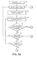
- the program in accordance with the present invention is illustrated in general flow chart fashion in FIG. 3.
- the system operates in accordance with a set of rules, as hereinafter more fully described, and these rules are stored in a dictionary (in memory) in the order that they are to be examined.
- Each rule is taken from the dictionary and asked to evaluate itself.
- a rule evaluates itself by examining one or more conditions that govern the applicability of the rule and these conditions are examined one by one in order.,
- the rule set is opened in block 32 and a first rule (or the next rule in sequence) is selected in block 34.
- a condition set is extracted for the particular rule under consideration, while the next (or first) condition in the condition set is selected in accordance with block 38.
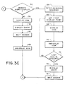
- decision block 40 it is ascertained whether the condition contains a query/display sequence and if the answer is yes, the program proceeds to decision block 54 in FIG. 3C where the question is asked whether the query includes an animation sequence, i. e. the moving portion of the circuit or a component thereof from one location to another. If the answer to this question is no, then the query is understood to call for displaying an icon or icons (such as illustrated at 26 and 28 in FIG.
- the icon is displayed per block 56.
- the query (or other comment) is displayed in window 30 in FIG. 2 in accordance with block 58 of the flow chart.
- An answer is awaited in block 60, i. e. a selection by the technician of either a yes or no answer in window 30, in answer to the query posted in window 30. After the technician indicates the answer, the icon is "undisplayed" in block 62.
- the pointing sequence operates as follows.
- the query/display has an address for the pointing location.
- the proper icon is sent a message to display itself at the appropriate location, and in displaying itself, the icon also stores a picture of the background that it is occluding.
- the query is generated in window 30 and the answer is awaited. Once the answer to the query is received, the icon is undisplayed by redisplaying the occluded background previously stored.
- the animation sequence operates in a similar. fashion.
- the principal difference is that there is a series of display actions at a sequence of points which are calculated from the path between the start and finish locations of the animation sequence.
- an animation sequence is fetched when the decision from block 54 is that an animation sequence is desired.
- the first display point is set in block 66 followed by the display of an icon in block 68.
- the icon in this case may comprise a portion, part or node of the circuit diagram rather than a probe icon or the like.
- An icon or icons are displayed at successive points to indicate movement in accordance with display actions at the series of points.
- the first icon is undisplayed in block 70, and in decision block 72 it is determined whether the last displayed icon is the last icon in the sequence.
- decision block 42 is entered and it is determined whether the particular condition is satisfied, i. e. whether the user has given an answer which will lead to the next condition in a diagnostic sequence or if the last condition has been satisfied such that some conclusion can be made. If the condition is not satisfied, return is made to block 34 and a next rule is tried. If the condition is satisfied, decision block 44 is entered and it is determined whether the condition is the last condition for the particular rule under consideration. If it is not, return is made to block 38 and a next condition associated with the rule is fetched. If it is the last condition, then block 46 in FIG. 3B is entered to acquire an "action set".
- the action set involves some kind of conclusion or possibly an animated movement for graphically demonstrating to the technician the particular curative action which is to be taken.
- An individual "action" is selected in block 48, and decision block 50 is entered where it is determined whether information is to be displayed. If it is, the sequence of FIG. 3C is again entered via decision block 54. If no animation sequence is directed, the path on the left side of the drawing is selected, and an icon, if any, is displayed in block 56 and/or a particular part or component, e.g. a faulty part or component, is highlighted.
- a conclusion in the nature of troubleshooting advice is directed for window 22 in FIG. 2. No-answer is awaited in block 60. The icon, if any, is again undisplayed in block 62, and return is made, in this instance, to decision block 52 in FIG. 3B.
- the animation sequence is fetched in block 64 and the first display point is selected in block 66.
- the icon displayed according to block 68, may comprise a part or portion of the circuit rather than a probe icon, and this part or portion, of the circuit, for example indicating a faulty component, may be moved across the display to a "work bench area" or the like.
- the icon may then be undisplayed in block 70 and a determination is made according to block 72 whether there is another icon in the sequence.
- the program includes three major components: a diagram manager, a rule processor, and a communications manager.
- the diagram manager can support several diagrams relating to the task at hand and manages the pointing relationships, e.g. by probe icons and the like, among these diagrams and between the diagrams and the rule processor.
- the rule processor interprets diagnostic rules to suggest troubleshooting operations to the technician.
- the rule processor decides which rules to process, i. e. which tests to perform next, and then sends off a request to the diagram manager to highlight or point with an icon to whatever parts or circuit points are relevant to that test.
- the communications manager consists of routines to handle miscellaneous display requirements such as English rule text and question-answer dialogues in the windows. This communication manager generates the questions, e.g. in window 30 in FIG. 2, and accepts answers via the same window.
- a separate rule acquisition subsystem is employed whereby the rules can be formulated and entered.
- the rule acquisition subsystem is not useful solely to the repair or troubleshooting of some particular apparatus such as the FG 502 Tektronix Function Generator employed as an example herein, but rather this rule acquisition system can be utilized for generating rules in a number of related environments for solving related problems. Problems of this type may be referred to as expert family problems. Perhaps the most natural examples occur in automatic troubleshooters for a variety of similar devices such as electronic instruments.
- the rule acquisition system is effective for generating rules for a family of problems employing a common task model.
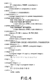
- GLIB General Language for Instrument Behavior
- FIG. 4 A simple subset of GLIB is shown in FIG. 4. " The subset illustrated is concerned solely with the acquisition of simple diagnostic rules and is not intended to represent the complete acquisition language. In the subset illustrated in FIG. 4, observations are limited to a single relationship between a measured value and a constant or other measured value. Conclusions are limited to the observations that a device is either functioning correctly or is failing.
- a structured interface language such as GLIB
- GLIB structured interface language
- menu-based acquisition is a technique wherein the expert does not generate or complete rules on . his own, but rather a menu displays alternative choices for each word in the rule as it is being selected.
- a single menu is employed consisting of only terminal tokens to choose from at any point in time.
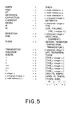
- the GLIB rules are processed to produce an expectation table utilized to determine which words are syntactically admissible at any point in a sentence, so that the correct menu can be constructed.
- An example of an expectation table, based only upon the previous word, is illustrated in FIG. 5.
- the next choice to be made is whether the VOLTAGE is of a single point (with respect to ground) or between two points.
- a node in the schematic may be referenced by either pointing to it or typing in the name. Our user chooses the latter.
- THEN is filled in automatically. Now a device must be specified as working or broken.
- the reference is made explicitly by typing the device number. In this case, the user points directly at the schematic employing a mouse or the like.
- Menu-based acquisition is not the only way to present a structured interface language.
- a more general structured interface language processor supports acquisition via typing or graphic selection or a mixture of the two.
- the pointing paradigm can be successfully used to enhance the cognitive transparency wherein each act of pointing is viewed as a linguistic act, namely a reference to the object being pointed at. Whenever it is appropriate to refer to an object in the GLIB sentence, the expert may instead point to an element in the diagram. The mechanism for referencing elements in a diagram is described hereinabove.
- a more generalized and sophisticated structured interface language processor is illustrated by means of the flow charts of FIGS. 6 and 7.
- the processor operates on an artificial intelligence system or workstation as hereinbefore disclosed.
- the knowledge engineer is not required to cast expert knowledge into a specific form for rules or rule compenents (which may be referred to as task ontology), but rather the rule acquisition process is more automated.
- the present invention involves capture of the ontology as well, and defines a complete grammar for acceptable utterances which can be converted into rules.
- the grammar and ontology can be completely defined for a whole class or family of problems for which it is necessary to build expert systems.
- a grammar appropriate for the present example is given in Appendix E and an ontology is given in Appendix F.
- the mechanism for acquisition of the expert knowledge consists of two parts: a parser for GLIB which allows the user to generate a statement in GLIB as illustrated in Fig. 6, and a rule generator depicted in FIG. 7.
- the GLIB parser is coded in SMALLTALK
- the rule generator is coded in SMALLTALK and generates rules coded in PROLOG..
- the parser assist.s or guides the expert.
- operation begins by the insertion of a grammar and dictionary of the GLIB language indicated at block 80 in FIG. 6.
- the grammar and dictionary are preprocessed to generate appropriate data structures for operation.
- initial expectations (similar to the expectation table of FIG. 5) are generated.
- controller 82 which senses mouse activity 84 and keyboard activity 86, collecting characters and tokens in buffer 88. Characters are placed in the.buffer as indicated by block 87..When a word appears in the buffer 88 it is compared with the expectations generated from the preprocessed grammar and dictionary. In the event of mouse activity, a "dummy fail" is placed in the buffer as indicated at 106 so that mouse activity can direct further selection as further noted in blocks 84a and 88a to which reference is made hereinbelow. If there is a match with expectations, a parse tree is updated and next expectations are generated. If there are no expectations, the statement is completed, and the parse tree is passed to the rule generation component.
- the comparison with expectations is indicated in block 90 and if the comparison is favorable, the parse tree is updated in block 92. Next expectations are then generated in block 94 with a return to block 90 for comparison. If there are no further expectations, the statement is completed, and the parse tree is passed to the rule generation component of the system as indicated at 96.
- a series of steps are taken to correct the input to match one of the expectations.
- a spelling corrector is invoked as indicated at block 98. If a match can occur with the spelling corrected, the procedure continues as before. If not, a phrase completion is attempted in block 100. If phrase completion is successful in generating a match, the procedure continues as before, with the tail of the phrase being stored as indicated in block 102. Finally if neither spelling correction or phrase completion is successful, the controller at 82a provides a menu which is displayed to the user as indicated in block 104. If the user selects a menu item, i. e. from possible expectations, the procedure continues with the selected item as specified by mouse activity at 84a and it is placed in the buffer as indicated at 88a.
- the processing goes back to compare with an expectation by return to block 90.
- the mouse also implements the pointing paradigm for rule acquisition as hereinbefore mentioned.
- the GLIB parser as illustrated in FIG. 6 is employed for the purpose of compiling results into forms dictated by rule construction grammar.
- the parser provides a parse tree which creates a structure that represents the meaning of the terminology.
- the parse tree shows the grouping and the relationship of words in a sentence, rather than just listing a series of words.
- associations are captured in the parse tree and these associations are used to provide an internal representation of the rules as well as an understandable representation thereof.
- the parse tree establishes the proper "bracketing" of an input sentence such that the burden of establishing this bracketing for association is not required of the expert user.
- a second part of the mechanism for rule generation receives parse tree information from the GLIB parser and uses the same to generate rules coded in PROLOG.
- the rule generator examines the nodes generated in the parse tree. Redundant nodes will be removed in block 112. The resultant data structure will be used to construct equations which functionally describe the statement, as noted in block 114.
- the semantics of the system may be checked. Semantics are optionally checked in blocks 116, 118 and 120. Processing continues if the semantics are acceptable, or if no semantic checking is performed.
- the GLIB acquisition grammar has the form of a semantic grammar where grammatical categories are based not on the theory of syntax, but instead on semantically meaningful units in the structures being acquired. For instance, sample semantic categories are ⁇ rule>, ⁇ observation>, ⁇ conclusion>, etc.
- rule generation grammar to parallel the rule acquisition grammar, for each projection of the form:
- the parser permits sentences to be created by selecting successive words or phrases from menus or by typing.
- the parser is able to check each word as it is entered by using an incremental, breadth-first parsing algorithm on the semantic grammar (GLIB).
- "Breadth-first” refers to the processing of all nodes at one parse tree level before proceeding to another level.
- the algorithm simultaneously considers all possible parses for the partial sentence so far entered.
- the semantic grammar (GLIB) combines syntactic and semantic information so that both the form and the meaning of a sentence are checked together.
- the use of a semantic grammar permits real time processing of both syntax and semantics. If a particular word does not match any of the current partial parses, the parser provides feedback to the expert operator, i.e. it builds a menu from all possible next steps in the parses and presents this menu to the operator for him to select a legal continuation.
- the parser builds an internal data structure which represents the syntactic structure of the completed GLIB statement.
- This syntactic representation comprises a parse tree.
- the parser parses incrementally from left to right and performs all checking on each word as it is entered.
- the parser follows the left-corner algorithm (see “On the Relative Efficiencies of Context-Free Grammar Recognizers” by Griffiths and Petrick, Communications of the ACM, May, 1965) modified to a parallel format so that it can follow all parses simultaneously.
- This algorithm builds phrases bottom-up from the left corner, i. e., rules are selected by the first symbol of their right-hand-sides. For example, given a phrase initial category c, a rule of the form X->c...
- the remaining rule segments of the right-hand side are predictions about the structure of the remainder of the phrase and are processed left-to-right. Subsequent inputs will directly match successive rule segments if the latter are terminal symbols of the grammar.
- a subparse is initiated.
- the subparse is also constructed bottom-up from the left corner, following the rule selection.
- the phrase formed may have the structure of the non-terminal category that originated the subparse and so complete the subparse. If there is no match, it will become the left-corner of a phrase that will eventually match the orignating category.
- the parser includes a reach- ability matrix (see Griffiths and Petrick supra) to provide top-down filtering of rule selection.
- the parser assigns a rule to an object instance of class "constituent" that attempts to match the rule against input as described above.
- object-oriented parsing can be found in "An Object-oriented Parser for Text Understanding” in "The Proceedings of the Eighth International Joint Conference on Artificial Intelligence", Düsseldorf, West Germany, 1982, pages 690-692, published by William Kaufmann, Inc., Los Altos, California.
- Parsing is driven by a "lookahead dictionary", a refinement of the expectation table mentioned on page 16. This associates constituent instances with the words that will advance their state. Through this dictionary those constituents that accept the current input are found and their state advanced according to the parsing algorithm. A new lookahead dictionary is then formed by interrogating the updated instances for their next rule segments. These segments are translated into words using a reverse dictionary. If no matches for the input are found, the lookahead dictionary's keys are used to form the aforementioned menu used for operator selection. It is seen that the program can guide an expert technician through sentence creation to keep him within GLIB. Assistance is only invoked when the technician deviates from GLIB.
- the parser creates a parse tree.
- the parser were given the following simple semantic grammar:
- This parse tree is next processed to convert it from a syntatic representation into a semantic representation.
- the parse tree which is actually produced is slightly different from the one shown.
- the parser accepts a lexical-functional grammar (which also describes GLIB) and produces a parse tree which includes functional equations for each constituent. These functional equations describe the semantic relationships of a constituent to its neighboring constituents. Going back to our example, a lexical functional form of the grammar would be:
- W e interpret this as saying that a rule has a condition part, COND, and a conclusion part, CNCL, and is printed in clausal-form as "rule (COND, C NCL)."
- the up-arrows (t) and down-arrows (t) are meta-symbols which refer to parent node (t) or to the node to which the equation belongs (+).
- a parse tree with attached functional equations is referred to as a constituent-structure, or c-structure. C-structures are actually produced by the parser instead of simply a parse tree. This is more efficient than building a parse tree and then attaching the functional equations at a later time.
- C-structures are converted to functional- structures, or f-structures, in the second phase or rule generation phase of the program.
- functional equations may be solved by instantiating the meta-symbols with actual nodes and assigning properties and values to the nodes according to the functional equations.
- the f-structure for our example is:
- the final phase of the program interprets the f-structures to produce PROLOG clauses. Most of the information required to produce the clauses is contained in the "form" property, as in the example. However, certain ordering is accomplished by the program. If the program were given the example used above we would find that it produces the PROLOG clause:
Landscapes
- Engineering & Computer Science (AREA)
- Theoretical Computer Science (AREA)
- General Engineering & Computer Science (AREA)
- Physics & Mathematics (AREA)
- General Physics & Mathematics (AREA)
- Evolutionary Computation (AREA)
- Computing Systems (AREA)
- Data Mining & Analysis (AREA)
- Computational Linguistics (AREA)
- Mathematical Physics (AREA)
- Software Systems (AREA)
- Artificial Intelligence (AREA)
- Computer Hardware Design (AREA)
- Quality & Reliability (AREA)
- Digital Computer Display Output (AREA)
- Devices For Executing Special Programs (AREA)
- Management, Administration, Business Operations System, And Electronic Commerce (AREA)
- Testing Or Calibration Of Command Recording Devices (AREA)
Applications Claiming Priority (2)
| Application Number | Priority Date | Filing Date | Title |
|---|---|---|---|
| US67819484A | 1984-12-04 | 1984-12-04 | |
| US678194 | 1984-12-04 |
Publications (2)
| Publication Number | Publication Date |
|---|---|
| EP0184088A2 true EP0184088A2 (de) | 1986-06-11 |
| EP0184088A3 EP0184088A3 (de) | 1988-04-20 |
Family
ID=24721784
Family Applications (1)
| Application Number | Title | Priority Date | Filing Date |
|---|---|---|---|
| EP85114860A Withdrawn EP0184088A3 (de) | 1984-12-04 | 1985-11-22 | Expertsystem |
Country Status (3)
| Country | Link |
|---|---|
| EP (1) | EP0184088A3 (de) |
| JP (1) | JPS61133468A (de) |
| CA (1) | CA1258136A (de) |
Cited By (4)
| Publication number | Priority date | Publication date | Assignee | Title |
|---|---|---|---|---|
| GB2197513A (en) * | 1986-11-14 | 1988-05-18 | Victoria State | Data processing system |
| GB2208950A (en) * | 1987-08-20 | 1989-04-19 | Fuji Heavy Ind Ltd | Motor vehicle fault diagnosis |
| EP0258553A3 (de) * | 1986-06-20 | 1990-06-13 | Mitsubishi Denki Kabushiki Kaisha | Kenntnisgegründetes Gerät zur Störungsbeseitigung unter Verwendung von Bildern zur Benutzung in einer Fabrik |
| US4975865A (en) * | 1989-05-31 | 1990-12-04 | Mitech Corporation | Method and apparatus for real-time control |
-
1985
- 1985-11-22 EP EP85114860A patent/EP0184088A3/de not_active Withdrawn
- 1985-11-26 CA CA000496256A patent/CA1258136A/en not_active Expired
- 1985-12-03 JP JP60272352A patent/JPS61133468A/ja active Pending
Non-Patent Citations (6)
| Title |
|---|
| ADVANCES IN INSTRUMENTATION, PROCEEDINGS OF THE ISA INTERNATIONAL CONFERENCE AND EXHIBIT, Houston, Texas, 22th - 25th October 1984, vol. 39, parts 1,2; pages 1081-1094, ISA, Pittsburgh, US; R.L. MOORE et al.: "Expert systems applications in industry" * |
| AUTOTESCON'83, INTERNATIONAL AUTOMATIC TESTING CONFERENCE, Fort Worth, Texas, 1st-3rd November 1983, pages 312-317, IEEE, New York, US; J.L. KUNERT: "Intelligent test generator" * |
| AUTOTESTCON'82, IEEE INTERNATIONAL AUTOMATIC TESTING CONFERENCE, Dayton, Ohio, 12th - 14th October 1982, pages 474-477, IEEE; M.F. BATTAGLIA et al.: "Innovative maintenance utilizing videodisc" * |
| AUTOTESTCON'83, INTERNATIONAL AUTOMATIC TESTING CONFERENCE, 1st-3rd November 1983, Fort Worth, Texas, pages 322-323, IEEE, New York, US; T.L. WILLIAMS: "A knowledge-based maintenance aid for diagnosing faults in electronic equipment" * |
| FGCS'84, PROCEEDINGS OF THE INTERNATIONAL CONFERENCE ON FIFTH GENERATION COMPUTER SYSTEMS, Tokyo, JP, 6th-9th November 1984, pages 582-588, ICOT, Tokyo, JP; H. MOTODA et al.: "A knowledge based system for plant diagnosis" * |
| W.B. RAUCH-HINDIN: "ARTIFICIAL INTELLIGENCE IN BUSINESS SCIENCE AND INDUSTRY", vol. 2, 1985, pages 194-207, Prentice-Hall, Inc., Englewood Cliffs, New Jersey, US * |
Cited By (4)
| Publication number | Priority date | Publication date | Assignee | Title |
|---|---|---|---|---|
| EP0258553A3 (de) * | 1986-06-20 | 1990-06-13 | Mitsubishi Denki Kabushiki Kaisha | Kenntnisgegründetes Gerät zur Störungsbeseitigung unter Verwendung von Bildern zur Benutzung in einer Fabrik |
| GB2197513A (en) * | 1986-11-14 | 1988-05-18 | Victoria State | Data processing system |
| GB2208950A (en) * | 1987-08-20 | 1989-04-19 | Fuji Heavy Ind Ltd | Motor vehicle fault diagnosis |
| US4975865A (en) * | 1989-05-31 | 1990-12-04 | Mitech Corporation | Method and apparatus for real-time control |
Also Published As
| Publication number | Publication date |
|---|---|
| CA1258136A (en) | 1989-08-01 |
| JPS61133468A (ja) | 1986-06-20 |
| EP0184088A3 (de) | 1988-04-20 |
Similar Documents
| Publication | Publication Date | Title |
|---|---|---|
| EP0184087B1 (de) | Regelerfassung für Expertsysteme | |
| Brusilovskiy | The construction and application of student models in intelligent tutoring systems | |
| Van Melle et al. | EMYCIN: A knowledge engineer’s tool for constructing rule-based expert systems | |
| EP0436459A1 (de) | Verfahren zur intelligenten Erläuterung von Hilfe in Übereinstimmung mit der Aktivität des Rechnerbenützers | |
| Lakin | Spatial parsing for visual languages | |
| Suzuki et al. | Tracediff: Debugging unexpected code behavior using trace divergences | |
| JPS61221873A (ja) | 自然言語による質問応答方式 | |
| Paul et al. | Further developments in the use of artificial intelligence techniques which formulate simulation problems | |
| EP0184088A2 (de) | Expertsystem | |
| Moore et al. | Discourse generation for instructional applications: Identifying and exploiting relevant prior explanations | |
| Schaeffer et al. | A minimal cognitive model for translating and post-editing | |
| Jacobson | ASTEK: a multi-paradigm knowledge aquisition tool for complex structured knowledge | |
| Li et al. | Visualizing Program Behavior: A Study of Enhanced Program Diagrams Using LLM | |
| Woodyard et al. | A natural language interface to a clinical data base management system | |
| Zengaffinen et al. | Can LLMs Model Incorrect Student Reasoning? A Case Study on Distractor Generation | |
| Ariav et al. | Designing conceptual models of dialog: A case for dialog charts | |
| Phillips et al. | An eclectic approach to building natural language interfaces | |
| Di Piazza et al. | Laps: Cases to models to complete expert systems | |
| Paul et al. | Artificial Intelligence aids in discrete-event digital simulation modelling | |
| JP3485202B2 (ja) | 故障診断装置 | |
| Liebowitz | Expert systems and telecommunications | |
| Nagao et al. | Evaluation of Learning Support System for Agent-Based C Programming | |
| Halewood et al. | A uniform graphical view of the program construction process: GRIPSE | |
| JPH0415828A (ja) | 推論方法及びシステム | |
| Rösner et al. | TECHDOC: Multilingual generation of online and offline instructional text |
Legal Events
| Date | Code | Title | Description |
|---|---|---|---|
| PUAI | Public reference made under article 153(3) epc to a published international application that has entered the european phase |
Free format text: ORIGINAL CODE: 0009012 |
|
| AK | Designated contracting states |
Kind code of ref document: A2 Designated state(s): DE FR GB NL |
|
| PUAL | Search report despatched |
Free format text: ORIGINAL CODE: 0009013 |
|
| AK | Designated contracting states |
Kind code of ref document: A3 Designated state(s): DE FR GB NL |
|
| 17P | Request for examination filed |
Effective date: 19880408 |
|
| 17Q | First examination report despatched |
Effective date: 19891113 |
|
| STAA | Information on the status of an ep patent application or granted ep patent |
Free format text: STATUS: THE APPLICATION HAS BEEN WITHDRAWN |
|
| 18W | Application withdrawn |
Withdrawal date: 19900503 |
|
| R18W | Application withdrawn (corrected) |
Effective date: 19900503 |
|
| RIN1 | Information on inventor provided before grant (corrected) |
Inventor name: ALEXANDER, JAMES H. Inventor name: FREILING, MICHAEL J. |