EP0184147A2 - Appareil à bande magnétique pour l'enregistrement de données - Google Patents
Appareil à bande magnétique pour l'enregistrement de données Download PDFInfo
- Publication number
- EP0184147A2 EP0184147A2 EP85115131A EP85115131A EP0184147A2 EP 0184147 A2 EP0184147 A2 EP 0184147A2 EP 85115131 A EP85115131 A EP 85115131A EP 85115131 A EP85115131 A EP 85115131A EP 0184147 A2 EP0184147 A2 EP 0184147A2
- Authority
- EP
- European Patent Office
- Prior art keywords
- tape
- magnetic tape
- guides
- magnetic
- movable
- Prior art date
- Legal status (The legal status is an assumption and is not a legal conclusion. Google has not performed a legal analysis and makes no representation as to the accuracy of the status listed.)
- Granted
Links
Images



Classifications
-
- G—PHYSICS
- G11—INFORMATION STORAGE
- G11B—INFORMATION STORAGE BASED ON RELATIVE MOVEMENT BETWEEN RECORD CARRIER AND TRANSDUCER
- G11B15/00—Driving, starting or stopping record carriers of filamentary or web form; Driving both such record carriers and heads; Guiding such record carriers or containers therefor; Control thereof; Control of operating function
- G11B15/18—Driving; Starting; Stopping; Arrangements for control or regulation thereof
- G11B15/1808—Driving of both record carrier and head
- G11B15/1875—Driving of both record carrier and head adaptations for special effects or editing
-
- G—PHYSICS
- G11—INFORMATION STORAGE
- G11B—INFORMATION STORAGE BASED ON RELATIVE MOVEMENT BETWEEN RECORD CARRIER AND TRANSDUCER
- G11B15/00—Driving, starting or stopping record carriers of filamentary or web form; Driving both such record carriers and heads; Guiding such record carriers or containers therefor; Control thereof; Control of operating function
- G11B15/56—Driving, starting or stopping record carriers of filamentary or web form; Driving both such record carriers and heads; Guiding such record carriers or containers therefor; Control thereof; Control of operating function the record carrier having reserve loop, e.g. to minimise inertia during acceleration measuring or control in connection therewith
-
- G—PHYSICS
- G11—INFORMATION STORAGE
- G11B—INFORMATION STORAGE BASED ON RELATIVE MOVEMENT BETWEEN RECORD CARRIER AND TRANSDUCER
- G11B15/00—Driving, starting or stopping record carriers of filamentary or web form; Driving both such record carriers and heads; Guiding such record carriers or containers therefor; Control thereof; Control of operating function
- G11B15/60—Guiding record carrier
- G11B15/602—Guiding record carrier for track selection, acquisition or following
-
- G—PHYSICS
- G11—INFORMATION STORAGE
- G11B—INFORMATION STORAGE BASED ON RELATIVE MOVEMENT BETWEEN RECORD CARRIER AND TRANSDUCER
- G11B15/00—Driving, starting or stopping record carriers of filamentary or web form; Driving both such record carriers and heads; Guiding such record carriers or containers therefor; Control thereof; Control of operating function
- G11B15/60—Guiding record carrier
- G11B15/61—Guiding record carrier on drum, e.g. drum containing rotating heads
- G11B15/615—Guiding record carrier on drum, e.g. drum containing rotating heads inside container
-
- G—PHYSICS
- G11—INFORMATION STORAGE
- G11B—INFORMATION STORAGE BASED ON RELATIVE MOVEMENT BETWEEN RECORD CARRIER AND TRANSDUCER
- G11B23/00—Record carriers not specific to the method of recording or reproducing; Accessories, e.g. containers, specially adapted for co-operation with the recording or reproducing apparatus ; Intermediate mediums; Apparatus or processes specially adapted for their manufacture
- G11B23/02—Containers; Storing means both adapted to cooperate with the recording or reproducing means
- G11B23/04—Magazines; Cassettes for webs or filaments
- G11B23/08—Magazines; Cassettes for webs or filaments for housing webs or filaments having two distinct ends
- G11B23/087—Magazines; Cassettes for webs or filaments for housing webs or filaments having two distinct ends using two different reels or cores
Definitions
- the invention relates to a magnetic tape device according to the preamble of claim 1.
- a magnetic tape device for data recording is known in which the magnetic tape can be moved back and forth between two separately stored coils, both coils being drivable via winding mandrels.
- Such magnetic tape devices are used for longitudinal recording, helical track recording or for cross track recording.
- the coils are usually in cassettes.
- the magnetic tape remains inside the cassette and the recording or scanning magnetic head is pressed from the outside against the tape located in the cassette between two tape guides.
- the magnetic tape is pulled out of the cassette and wrapped around a head drum before recording or scanning.
- the magnetic tape can also remain in the cassette during cross-track recording.
- the tape that can be moved back and forth at the scanning point is arched transversely to its direction of travel around a head drum wheel whose axis of rotation is parallel to the direction of tape travel, the tracks of which are thus written onto the tape essentially or almost perpendicular to the direction of tape travel.
- the magnetic tape device with cross-track recording it has also been proposed to shift the head wheel used for recording and / or scanning in the axial direction for still picture reproduction or for track control.
- the invention has for its object to provide a magnetic tape g et up instrument in which a tracking control and / or a still image without or with reduced head displacement is achieved.
- This object is achieved in a magnetic tape device according to the preamble of claim 1 by the features described in the characterizing part of claim 1. Developments of the invention are described in the subclaims.
- the object is achieved in that the magnetic tape stretched, moved or unmoved between the tape guides can be moved relative to a reference point without using the primary tape drive.
- FIG. 1 shows a magnetic tape device with two spools or reels 2 and 3 arranged in a cassette 1, between which a magnetic tape 4 can be moved back and forth.
- the magnetic tape 4 is brought out in the longitudinal end face 5 of the cassette 1, for example by means of a nose 6 and in the area of the scanning point for transverse track recording adapted to the shape of a head wheel 7.
- This is done, for example, by means of two pieces of felt 8 and 9, which are arranged on both sides of the scanning point and leave a groove-like depression 10 between them.
- the felt pieces 8, 9 are fastened on a flexible base 11, which is fixed in position in the cassette 1 and allow a flexible adaptation of the felt pieces 8, 9 to the outer diameter of the head drum 7.
- the band 4 is nestled over the felt pieces E, 9 on the head wheel 7 and tensioned so that optimum scanning properties of the band 4 in the area of the heads 7a of the head wheel 7 result (band-head contact).
- the Koptrod 7 is as a head drum or Band guide cylinder formed or inserted into a head drum.
- the curvature of the belt 4 is dimensioned such that the wrap angle of the belt area is between 40 and 70 °, depending on the head wheel or head drum diameter.
- a tape guide 12a or 12b is provided in the area of the nose or exit point 6 from the cassette 1 before the entry to the scanning point or in the area of the entry point 6b into the cassette behind the scanning point.
- the boundary lines of the longitudinal section of these guides 12a, 12b are essentially biconcave. It is thereby achieved that the band 4 is bulged in front of the entry point for scanning.
- Fig. 2 shows a partial sectional view of the drive system for the head wheel 7 in the working position together with an inserted magnetic tape cassette 1, in which a magnetic tape 4 is driven.
- the magnetic tape 4 lies between the head wheel 7 or a tape guide cylinder 27 containing the head wheel 7 and the pressure felts 8, 9.
- the tape guide cylinder 27 is fixed in this example, but does not rotate.
- the magnetic tape 4 is arched in the effective area of the magnetic heads 7a arranged on the head wheel 7 in such a way that its surface is adapted to the circle described by the magnetic heads 7a. This exact adjustment enables good head-to-head contact.
- the head wheel 7 is provided with 2n heads 7a, the gaps of which alternately have different azimuth angles.
- the supply or removal of the signal voltages to and from the magnetic heads 7a is done by means of two rotary transformers 24.
- the magnetic heads 7a are electrically connected to the same azimuth angle, each with a rotary transformer 24. This can be done by connecting the magnetic head coils in series or in parallel.
- the head wheel 7 is driven by the drive motor 21, which is arranged on a common axis 23 with the head wheel 7 and an electromechanical transducer 25 used for readjustment.
- the electromechanical converter 25 consists of a coil 26 into which a soft iron core 22 and thus the axis carrying it is pulled against a spring 28 when a control voltage is applied.
- the converter 25 is preferably part of the drive motor 21, so that the rotor of the motor 21 is displaced in the axial direction when the control voltage is applied.
- a flexible base 11 would be used for the pieces of felt 8.9, a film made of copper beryllium. With non-magnetic properties, this film has sufficient elasticity and fatigue strength.
- the pad 11 can itself be flat in the case of shaped pieces of felt 8, 9.
- the pad 11 can also be adapted itself to the head wheel diameter and be provided with felt pieces 8.9 of a uniformly flat construction.
- Fig. 3 a modification of the cassette 1 is shown, in which the tape reels 2 and 3 are no longer driven directly, but are rotatably supported in the cassette 1 without their own direct drive.
- the actual drive is carried out by a separate roller 19 which is inserted into the cassette 1 from the outside and drives the tape 4 itself in the area between the tape reels 2, 3.
- a cassette with such a drive is described, for example, in German patents P 11 87 028 and 22 30 281.
- the cassette is designed in such a way that the band guides or rollers 12a, 12b, which are biconcavely shaped for arching the band, are arranged near the edges of the cassette 1, which delimit the longitudinal end face 5 facing the head wheel 7.
- the head wheel 7 is arranged such that the scanning point is close to the roller 7 and the motor 21 driving the head wheel 1 is outside the area of the cassette 2. This may keep magnetic stray fields of the motor 21 away from the cassette 1 and the tape 4. Possibly. Magnetic fields that are still disruptive can be kept away from the tape by shielding in the device and / or the cassette.
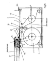
- FIG. 4 shows a development according to the invention of the cassette 1 shown in FIG. 1, which enables a function similar to the converter 25.
- the band 4 is not led directly from the band guides 12a, 12b to the band windings 2, 3, but is guided around one or two further band guides 36, 37 to form one or two band loops 40.
- the tape guides 12a, 12b can be moved essentially parallel to the tape running direction in the scanning area.
- two levers 30, 31 are provided which can be pivoted together about one axis 34, 35 by slides 32, 33.
- the shift takes place as a function of control signals for setting the track and / or for generating tracks corresponding to an exact image or partial images. In this way, the track position relative to the heads 7a can be corrected and / or still images can be written.
- FIG. 5 shows a modification of the arrangement shown in FIG. 4, corresponding to FIG. 3.
- the band guides 12a, 12b can be displaced, as in FIG. 4, by swivel levers or by electrically coupled or mechanically coupled means.
- Fig. 6 shows an embodiment with a molded body 41, which enables simultaneous displacement of the two band guides 12a, 12b.
- the two band guides 12a, 12b are rotatably fastened on the molded body 41 in FIG. 6.
- the molded body 41 is slidably mounted in the cassette 1.
- An approach 42 is accessible from the outside and can be moved by an electromechanical transducer, not shown, which can be set by control signals with an accuracy required for the correction or displacement of the track bearing.
- Fi g. 7 shows a path-time diagram with a movement sequence that can be achieved with the invention for fast forward.
- the ordinate s shows the paths, the abscissa t the time.
- the tape is moved at the scanning point 10 at a continuous, steady speed, as is customary for reading and writing the tracks.
- the signal for Figure 1 is read into a memory and also displayed on a screen.
- a component of motion is superimposed on the belt 4 by shifting the belt 4 in the direction of the belt running by shifting the molded body 41. This results in an initially accelerated, then fast and finally braked movement in t2, which leads the head 7a to the beginning of the 7th image, for example.
- the first image from the memory is repeated during the advance.
- image 7 is read and simultaneously reproduced.
- fast rewind is also possible.
- Fig. 8 shows a modification in which the axes 43 of the tape guide rollers 12a, 12b protrude from the cassette and engage in actuating means such as the controlled approach 42.
- the approach 42 can be controlled by electromechanical transducers. However, it is also possible to provide profile control for certain applications.
Landscapes
- Engineering & Computer Science (AREA)
- Signal Processing (AREA)
- Adjustment Of The Magnetic Head Position Track Following On Tapes (AREA)
- Registering, Tensioning, Guiding Webs, And Rollers Therefor (AREA)
- Signal Processing For Digital Recording And Reproducing (AREA)
- Recording Or Reproducing By Magnetic Means (AREA)
Priority Applications (1)
| Application Number | Priority Date | Filing Date | Title |
|---|---|---|---|
| AT85115131T ATE70655T1 (de) | 1984-12-01 | 1985-11-28 | Magnetbandgeraet fuer datenaufzeichnung. |
Applications Claiming Priority (2)
| Application Number | Priority Date | Filing Date | Title |
|---|---|---|---|
| DE3443879 | 1984-12-01 | ||
| DE19843443879 DE3443879A1 (de) | 1984-12-01 | 1984-12-01 | Magnetbandgeraet fuer datenaufzeichnung |
Publications (3)
| Publication Number | Publication Date |
|---|---|
| EP0184147A2 true EP0184147A2 (fr) | 1986-06-11 |
| EP0184147A3 EP0184147A3 (en) | 1987-09-09 |
| EP0184147B1 EP0184147B1 (fr) | 1991-12-18 |
Family
ID=6251657
Family Applications (1)
| Application Number | Title | Priority Date | Filing Date |
|---|---|---|---|
| EP85115131A Expired - Lifetime EP0184147B1 (fr) | 1984-12-01 | 1985-11-28 | Appareil à bande magnétique pour l'enregistrement de données |
Country Status (5)
| Country | Link |
|---|---|
| US (1) | US4769726A (fr) |
| EP (1) | EP0184147B1 (fr) |
| JP (1) | JPS61180953A (fr) |
| AT (1) | ATE70655T1 (fr) |
| DE (2) | DE3443879A1 (fr) |
Cited By (2)
| Publication number | Priority date | Publication date | Assignee | Title |
|---|---|---|---|---|
| EP0336504A1 (fr) * | 1988-04-05 | 1989-10-11 | Koninklijke Philips Electronics N.V. | Appareil à bande magnétique muni d'une unité de réglage pour commander des longueurs tampon de bande, la tension de bande et le défilement de la bande |
| US4975792A (en) * | 1988-04-05 | 1990-12-04 | U.S. Philips Corporation | Magnetic-tape apparatus comprising a threading mechanism for the displacement of a magnetic tape and a belt so as to form tape buffers |
Families Citing this family (2)
| Publication number | Priority date | Publication date | Assignee | Title |
|---|---|---|---|---|
| JPS63273127A (ja) * | 1987-04-30 | 1988-11-10 | Nec Home Electronics Ltd | 印字デ−タ表示装置 |
| JP2586576B2 (ja) * | 1988-05-26 | 1997-03-05 | キヤノン株式会社 | 磁気記録再生装置 |
Family Cites Families (11)
| Publication number | Priority date | Publication date | Assignee | Title |
|---|---|---|---|---|
| US2963555A (en) * | 1955-02-21 | 1960-12-06 | Cons Electrodynamics Corp | Speed controls for reproduction of tape recordings |
| US3005056A (en) * | 1956-02-02 | 1961-10-17 | Columbia Broadcasting Syst Inc | Recording reproducing system |
| US2979557A (en) * | 1957-10-01 | 1961-04-11 | Rca Corp | Recording and reproducing system |
| US2979558A (en) * | 1957-10-02 | 1961-04-11 | Rca Corp | Recording and reproducing system |
| US3050594A (en) * | 1957-10-30 | 1962-08-21 | Rca Corp | Position control system |
| US3213204A (en) * | 1961-03-21 | 1965-10-19 | Nippon Electric Co | Magnetic tape recorder |
| US3141065A (en) * | 1962-03-27 | 1964-07-14 | Rca Corp | Servo system |
| US3692255A (en) * | 1971-06-17 | 1972-09-19 | Minnesota Mining & Mfg | Belt driven tape cartridge |
| JPS5056204A (fr) * | 1973-09-14 | 1975-05-16 | ||
| NL7500730A (nl) * | 1975-01-22 | 1976-07-26 | Philips Nv | Machine voor het magnetisch opnemen of weerge- ven van signalen met grote bandbreedte, zoals video-signalen op magneetband. |
| US4167023A (en) * | 1976-06-09 | 1979-09-04 | Rca Corporation | Rotating head recorder with different recording and playback speeds |
-
1984
- 1984-12-01 DE DE19843443879 patent/DE3443879A1/de not_active Withdrawn
-
1985
- 1985-11-28 DE DE8585115131T patent/DE3584952D1/de not_active Expired - Lifetime
- 1985-11-28 EP EP85115131A patent/EP0184147B1/fr not_active Expired - Lifetime
- 1985-11-28 AT AT85115131T patent/ATE70655T1/de not_active IP Right Cessation
- 1985-12-02 US US06/803,807 patent/US4769726A/en not_active Expired - Fee Related
- 1985-12-02 JP JP60269566A patent/JPS61180953A/ja active Pending
Cited By (3)
| Publication number | Priority date | Publication date | Assignee | Title |
|---|---|---|---|---|
| EP0336504A1 (fr) * | 1988-04-05 | 1989-10-11 | Koninklijke Philips Electronics N.V. | Appareil à bande magnétique muni d'une unité de réglage pour commander des longueurs tampon de bande, la tension de bande et le défilement de la bande |
| US4970612A (en) * | 1988-04-05 | 1990-11-13 | U.S. Philips Corporation | Magnetic tape apparatus comprising a control unit for controlling tape buffers, the tape tension and the tape-transport |
| US4975792A (en) * | 1988-04-05 | 1990-12-04 | U.S. Philips Corporation | Magnetic-tape apparatus comprising a threading mechanism for the displacement of a magnetic tape and a belt so as to form tape buffers |
Also Published As
| Publication number | Publication date |
|---|---|
| EP0184147B1 (fr) | 1991-12-18 |
| DE3443879A1 (de) | 1986-06-05 |
| US4769726A (en) | 1988-09-06 |
| EP0184147A3 (en) | 1987-09-09 |
| ATE70655T1 (de) | 1992-01-15 |
| JPS61180953A (ja) | 1986-08-13 |
| DE3584952D1 (de) | 1992-01-30 |
Similar Documents
| Publication | Publication Date | Title |
|---|---|---|
| DE2904983A1 (de) | Magnetaufzeichnungs- und wiedergabevorrichtung | |
| DE2807856A1 (de) | Positioniervorrichtung | |
| DE2535780C3 (de) | Magnetbandlaufwerk für Videobandgeräte mit Längsspuraufzeichnung | |
| DE1127942B (de) | Magnetbandgeraet zur Aufzeichnung und/oder Wiedergabe von breitbandigen Signalen | |
| DE1144324B (de) | Vorrichtung zur magnetischen Aufzeichnung von Fernsehbild- und -tonsignalen | |
| EP0132883A2 (fr) | Moteur linéaire pour effectuer un mouvement rapide de va-et-vient d'une pièce d'un induit glissant affectée d'une masse | |
| EP0184147B1 (fr) | Appareil à bande magnétique pour l'enregistrement de données | |
| DE1175726B (de) | Einrichtung zur Fuehrung eines Magnetbandes bei einem der Aufzeichnung und Wiedergabe breit-bandiger Signale dienenden Magnetbandgeraet | |
| DE69019743T2 (de) | Magnetische aufzeichnung und wiedergabevorrichtung. | |
| WO1984002797A1 (fr) | Mecanisme d'entrainement pour magnetoscope | |
| DE1774608C3 (de) | Verfahren zum Kopieren von Magnetbändern und Einrichtung zur Durchführung des Verfahrens | |
| DE2313007A1 (de) | Kassettenrekorder | |
| DE3415595C2 (de) | Magnetbandgerät | |
| CH658330A5 (en) | Method of transporting a recording tape to be wound in a cassette and cassette for carrying out the method | |
| DE2420743C3 (fr) | ||
| EP0197333A2 (fr) | Procédé d'enregistrement d'un signal sur un support d'enregistrement en forme de bande | |
| DE68917705T2 (de) | Riemenangetriebenes Bandlaufwerk mit Rückschlagschutz. | |
| DE3005328C2 (de) | Gerät zum Aufzeichnen oder Wiedergeben elektrischer Signale | |
| EP0182901B1 (fr) | Appareil a bande magnetique | |
| DE2112029C3 (de) | Einrichtung zum bidirektionalen Antrieb und Spannen eines Aufzeichnungsbandes | |
| DE2522899C2 (de) | Abtasteinrichtung für ein Magnetbandgerät | |
| DE3025536A1 (de) | Magnetbandkassette und magnetbandgeraet zum abspielen dieser kassette | |
| DE2554028C3 (de) | Video-Magnetkopfeinheit | |
| EP0423883A2 (fr) | Appareil à bande et disposition à galet presseur pour cet appareil | |
| DE2858044C2 (fr) |
Legal Events
| Date | Code | Title | Description |
|---|---|---|---|
| PUAI | Public reference made under article 153(3) epc to a published international application that has entered the european phase |
Free format text: ORIGINAL CODE: 0009012 |
|
| AK | Designated contracting states |
Kind code of ref document: A2 Designated state(s): AT BE CH DE FR GB IT LI LU NL SE |
|
| PUAL | Search report despatched |
Free format text: ORIGINAL CODE: 0009013 |
|
| AK | Designated contracting states |
Kind code of ref document: A3 Designated state(s): AT BE CH DE FR GB IT LI LU NL SE |
|
| RHK1 | Main classification (correction) |
Ipc: G11B 15/60 |
|
| 17P | Request for examination filed |
Effective date: 19880212 |
|
| 17Q | First examination report despatched |
Effective date: 19890728 |
|
| GRAA | (expected) grant |
Free format text: ORIGINAL CODE: 0009210 |
|
| AK | Designated contracting states |
Kind code of ref document: B1 Designated state(s): AT BE CH DE FR GB IT LI LU NL SE |
|
| REF | Corresponds to: |
Ref document number: 70655 Country of ref document: AT Date of ref document: 19920115 Kind code of ref document: T |
|
| REF | Corresponds to: |
Ref document number: 3584952 Country of ref document: DE Date of ref document: 19920130 |
|
| ITF | It: translation for a ep patent filed | ||
| ET | Fr: translation filed | ||
| GBT | Gb: translation of ep patent filed (gb section 77(6)(a)/1977) | ||
| PLBE | No opposition filed within time limit |
Free format text: ORIGINAL CODE: 0009261 |
|
| STAA | Information on the status of an ep patent application or granted ep patent |
Free format text: STATUS: NO OPPOSITION FILED WITHIN TIME LIMIT |
|
| PGFP | Annual fee paid to national office [announced via postgrant information from national office to epo] |
Ref country code: LU Payment date: 19921029 Year of fee payment: 8 Ref country code: AT Payment date: 19921029 Year of fee payment: 8 |
|
| PGFP | Annual fee paid to national office [announced via postgrant information from national office to epo] |
Ref country code: BE Payment date: 19921118 Year of fee payment: 8 |
|
| PGFP | Annual fee paid to national office [announced via postgrant information from national office to epo] |
Ref country code: GB Payment date: 19921119 Year of fee payment: 8 |
|
| PGFP | Annual fee paid to national office [announced via postgrant information from national office to epo] |
Ref country code: FR Payment date: 19921120 Year of fee payment: 8 |
|
| PGFP | Annual fee paid to national office [announced via postgrant information from national office to epo] |
Ref country code: SE Payment date: 19921123 Year of fee payment: 8 |
|
| PGFP | Annual fee paid to national office [announced via postgrant information from national office to epo] |
Ref country code: NL Payment date: 19921130 Year of fee payment: 8 Ref country code: CH Payment date: 19921130 Year of fee payment: 8 |
|
| 26N | No opposition filed | ||
| PGFP | Annual fee paid to national office [announced via postgrant information from national office to epo] |
Ref country code: DE Payment date: 19921224 Year of fee payment: 8 |
|
| EPTA | Lu: last paid annual fee | ||
| PG25 | Lapsed in a contracting state [announced via postgrant information from national office to epo] |
Ref country code: LU Free format text: LAPSE BECAUSE OF NON-PAYMENT OF DUE FEES Effective date: 19931128 Ref country code: GB Effective date: 19931128 Ref country code: AT Effective date: 19931128 |
|
| PG25 | Lapsed in a contracting state [announced via postgrant information from national office to epo] |
Ref country code: SE Effective date: 19931129 |
|
| PG25 | Lapsed in a contracting state [announced via postgrant information from national office to epo] |
Ref country code: LI Effective date: 19931130 Ref country code: CH Effective date: 19931130 Ref country code: BE Effective date: 19931130 |
|
| BERE | Be: lapsed |
Owner name: TELEFUNKEN FERNSEH UND RUNDFUNK G.M.B.H. Effective date: 19931130 |
|
| PG25 | Lapsed in a contracting state [announced via postgrant information from national office to epo] |
Ref country code: NL Effective date: 19940601 |
|
| NLV4 | Nl: lapsed or anulled due to non-payment of the annual fee | ||
| GBPC | Gb: european patent ceased through non-payment of renewal fee |
Effective date: 19931128 |
|
| PG25 | Lapsed in a contracting state [announced via postgrant information from national office to epo] |
Ref country code: FR Effective date: 19940729 |
|
| REG | Reference to a national code |
Ref country code: CH Ref legal event code: PL |
|
| PG25 | Lapsed in a contracting state [announced via postgrant information from national office to epo] |
Ref country code: DE Effective date: 19940802 |
|
| REG | Reference to a national code |
Ref country code: FR Ref legal event code: ST |
|
| EUG | Se: european patent has lapsed |
Ref document number: 85115131.6 Effective date: 19940610 |