EP0184176A2 - Antriebs- und Lenkvorrichtung - Google Patents
Antriebs- und Lenkvorrichtung Download PDFInfo
- Publication number
- EP0184176A2 EP0184176A2 EP85115273A EP85115273A EP0184176A2 EP 0184176 A2 EP0184176 A2 EP 0184176A2 EP 85115273 A EP85115273 A EP 85115273A EP 85115273 A EP85115273 A EP 85115273A EP 0184176 A2 EP0184176 A2 EP 0184176A2
- Authority
- EP
- European Patent Office
- Prior art keywords
- drive
- wheel
- front wheel
- frame
- motor
- Prior art date
- Legal status (The legal status is an assumption and is not a legal conclusion. Google has not performed a legal analysis and makes no representation as to the accuracy of the status listed.)
- Ceased
Links
Images


Classifications
-
- B—PERFORMING OPERATIONS; TRANSPORTING
- B62—LAND VEHICLES FOR TRAVELLING OTHERWISE THAN ON RAILS
- B62K—CYCLES; CYCLE FRAMES; CYCLE STEERING DEVICES; RIDER-OPERATED TERMINAL CONTROLS SPECIALLY ADAPTED FOR CYCLES; CYCLE AXLE SUSPENSIONS; CYCLE SIDECARS, FORECARS, OR THE LIKE
- B62K5/00—Cycles with handlebars, equipped with three or more main road wheels
- B62K5/02—Tricycles
- B62K5/023—Tricycles specially adapted for disabled riders, e.g. personal mobility type vehicles with three wheels
- B62K5/025—Tricycles specially adapted for disabled riders, e.g. personal mobility type vehicles with three wheels power-driven
-
- B—PERFORMING OPERATIONS; TRANSPORTING
- B62—LAND VEHICLES FOR TRAVELLING OTHERWISE THAN ON RAILS
- B62M—RIDER PROPULSION OF WHEELED VEHICLES OR SLEDGES; POWERED PROPULSION OF SLEDGES OR SINGLE-TRACK CYCLES; TRANSMISSIONS SPECIALLY ADAPTED FOR SUCH VEHICLES
- B62M7/00—Motorcycles characterised by position of motor or engine
- B62M7/10—Motorcycles characterised by position of motor or engine with the engine over the front wheel
-
- B—PERFORMING OPERATIONS; TRANSPORTING
- B62—LAND VEHICLES FOR TRAVELLING OTHERWISE THAN ON RAILS
- B62K—CYCLES; CYCLE FRAMES; CYCLE STEERING DEVICES; RIDER-OPERATED TERMINAL CONTROLS SPECIALLY ADAPTED FOR CYCLES; CYCLE AXLE SUSPENSIONS; CYCLE SIDECARS, FORECARS, OR THE LIKE
- B62K5/00—Cycles with handlebars, equipped with three or more main road wheels
- B62K2005/001—Suspension details for cycles with three or more main road wheels
Definitions
- the invention relates generally to a tricycle vehicle and in particular to a drive and steering device for a battery-operated tricycle vehicle with at least one drive motor for the front wheel and / or the two rear wheels.
- the object of the invention is to provide a device for the steering mechanism, the front wheel suspension and the drive as a structural unit for an electric vehicle of the type outlined at the outset, so that the vehicle can be produced economically and is not technically complex and is maintenance-free because all components are easily accessible and can be repaired and / or replaced with a minimum of effort if required.
- a carrier with a spaced from it but connected to it steering mechanism and with a sleeve receiving the cross member of a frame and the frame is attached to an electric motor and transmission comprising drive and rotatably supports at least one drive wheel coupled to the motor.
- the main advantage of this design according to the invention of an arrangement comprising the steering mechanism, the front wheel suspension and the drive is that a vehicle equipped therewith has extremely stable driving behavior. Overall, there is an extremely compact drive unit with extremely low losses, which also improves the traction of the front wheel due to its own weight, especially since the center of gravity of the engine is essentially on the axis of the front wheel.
- the arrangement is partially disassembled and comes with very few movable parts, so that the overall life is increased.
- the angle of the steering column can be fixed variably depending on the type. The entire device is arranged protected within the overhanging plastic / metal body.
- the steering mechanism 2 comprises a sprocket 8 which is connected to the head of a frame 4.
- a profile part 12 is attached to the side of the frame and carries the receptacle 11 for a steering tube of a steering wheel 13.
- a sprocket wheel 10 is seated on the steering tube, a cam chain being guided around the two unequal gear wheels 8 and 10.
- a deflection roller 14 ensures at least one curve chain angle compensation.
- the arrangement is such that a carrier 1, to which the profile part 12 is welded, is provided with a cylindrical sleeve for receiving a cross member 3, 10.
- Device according to one of the preceding claims characterized in that protective brackets are provided on the frame (4) in front of and behind the front wheel, which in turn is protected by the high-impact-resistant body.
- a support plate of the electric motor is fastened by means of screws and nuts and slidably against the upper frame plate of the frame 4.
- two side rails extend obliquely downwards from the frame in the direction of travel.
- At least one side rail 18 has at its lower free end a receptacle for a sprocket Z2, which is seated on an axis of rotation 19 and is non-rotatably connected to a further sprocket Z3.
- a swing arm 17 (FIG. 3) is articulated, which extends: to a component seated on the front wheel axle, a spring strut 16, the upper region of which is fastened to the frame 4, being arranged on the axle .
- FIG. 3 there is thus the possibility of damping and shingling any vibrations that occur, the spring travel of the strut 17 being marked with X in FIG.
- a drive chain 21 extends around the pinion Z1 of the electric motor 6 and the associated larger sprocket Z2, so that the drive from the electric motor 6 directly to the front wheel 7 is transmitted.
- the gear ratio of the sprockets Z1, Z2, Z3 and Z4 to each other can be determined according to the respective application, ie depending on the desired torque and speed.
- the electric motor is arranged on the plate of the frame 4 in such a way that its drive axis, viewed in the direction of travel, lies essentially in the same plane as the axis of the front wheel hub 25.
- the electric motor can be adjusted with its carrier plate, so that the drive chain 21 can also be retensioned.
- the motor arranged in the center of gravity drives the front wheel directly via the two chains 21, 22.
- the front wheel rocker shown in FIG. 1 can preferably have elements for the purpose of damping and springing at the pivot point. Excellent damping and suspension is provided by the shock absorber shown in FIG. 3, and there is also the possibility of providing a shock absorber on both sides of the front wheel. An additional advantage is that the damping and suspension is variable by changing the mounting positions of the strut.
- the frame 4 with its plate supporting the motor is a unitary welded construction.
- the entire system shown in FIGS. 1 and 4 is largely maintenance-free. If there should be any malfunctions, there is an optimal access dependence in the L enk-, if front wheel and drive region of the device.
- the hand parking brake which is provided in the front wheel drum and can be actuated via a cable is not shown. The handbrake is locked using a hand lever on the dashboard with the simplest type of locking and unlocking lever.
Landscapes
- Engineering & Computer Science (AREA)
- Chemical & Material Sciences (AREA)
- Combustion & Propulsion (AREA)
- Mechanical Engineering (AREA)
- Transportation (AREA)
- Automatic Cycles, And Cycles In General (AREA)
- Power Steering Mechanism (AREA)
- Steering-Linkage Mechanisms And Four-Wheel Steering (AREA)
- Arrangement Or Mounting Of Propulsion Units For Vehicles (AREA)
- Steering Devices For Bicycles And Motorcycles (AREA)
Abstract
Description
- Die Erfindung betrifft allgemein ein Dreiradfahrzeug und insbesondere eine Antrieb- und Lenkvorrichtung für ein batteriebetriebenes Dreiradfahrzeug mit wenigstens einem Antriebsmotor für das Vorderrad und/oder die beiden Hinterräder.
- Bisher bekannte batteriebetriebene Fahrzeuge weisen hinsichtlich ihrer Fahrleistung, Wendigkeit und Einsatzmöglichkeit erhebliche Nachteile auf, weil sie für ihren Antrieb und Lenkung erheblichen Platz und Gewicht beanspruchen und kostenaufwendig in der Fertigung sind.
- Die der Erfindung zugrundeliegende Aufgabe besteht darin, für ein Elektrofahrzeug der eingangs umrissenen Art eine die Lenkmechanik, die Vorderradaufhängung und den Antrieb umfassende Vorrichtung als Baueinheit zu schaffen, so daß das Fahrzeug wirtschaftlich herzustellen ist und technisch nicht aufwendig konstruiert sowie wartungsfrei ist, weil alle Bauteile leicht zugänglich sind und bei Bedarf mit einem Minimum an Aufwand repariert und/oder ausgetauscht werden können.
- Diese Aufgabe wird erfindungsgemäß dadurch gelöst, daß am vorderen Abschnitt einer die Hinterräder lagernden integrierten Metall/Kunststoff-Karosserie ein Träger mit von ihm beabstandeter jedoch mit ihm verbundener Lenkmechanik und mit einer die Traverse eines Rahmens aufnehmenden Hülse befestigt ist, und daß der Rahmen einen Elektromotor und Getriebe umfassenden Antrieb trägt und mindestens ein mit dem Motor gekuppeltes Antriebsrad drehbar lagert.
- Zweckmäßige weitere Ausgestaltungen der erfindungsgemäßen Vorrichtung ergeben sich aus den Unteransprüchen.
- Der wesentliche Vorteil dieser erfindungsgemäßen Ausbildung einer die Lenkmechanik, die Vorderradaufhängung und den Antrieb umfassende Anordnung besteht darin, daß ein damit ausgerüstetes Fahrzeug ein äußerst stabiles Fahrverhalten aufweist. Insgesamt ergibt sich ein außerordentlich kompaktes Antriebsaggregat mit extrem geringen Verlusten, das zudem auch durch sein Eigengewicht die Bodenhaftung des Vorderrades verbessert, zumal der Schwerpunkt des Motors im wesentlichen auf der Achse des Vorderrades liegt. Die Anordnung ist teilweise auseinandernehmbar und kommt mit sehr wenig bewegbaren Teilen aus, so daß die Lebensdauer insgesamt erhöht ist. Die Winkelstellung der Lenksäule ist je nach Type variabel fixierbar. Die gesamte Vorrichtung ist innerhalb der überhängenden Kunststoff/Metallkarosserie geschützt angeordnet.
- Die Erfindung wird nachfolgend an einem Λusführungsbeispiel anhand der beigefügten Zeichnung näher erläutert.
- In der Zeichnung zeigen:
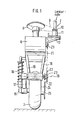
- Fig. 1 eine Vorderansicht der Anordnung mit der Vorderradaufhängung und einseitigem Antrieb,
- Fig. 2 eine der Anordnung nach Fig. 1 ähnliche Konstruktion mit beidseitiger Halterung,
- Fig. 3 eine schematische Seitenansicht der erfindungsgemäßen Vorrichtung,
- Fig. 4 eine Seitenansicht der Lenkmechanik.
- Wie in Fig. 1 und 4 gezeigt ist, umfaßt die Lenkmechanik 2 ein Kettenzahnrad 8, das mit dem Kopf eines Rahmens 4 verbunden ist. Seitlich vom Rahmen ist ein Profilteil 12 befestigt welches die Aufnahme 11 für ein Lenkrohr eines Lenkrades 13 trägt. Auf dem Lenkrohr sitzt ein Kettenzahnrad 10, wobei eine Kurvenkette um die beiden ungleichen Zahnräder 8 und 10 geführt ist. Für wenigstens einen Kurvenkettenwinkelausgleich sorgt hierbei eine Umlenkrolle 14. Dabei ist die Anordnung so getroffen, daß ein Träger 1, an welchem das Profilteil 12 verschweißt ist, mit einer zylindrischen Hülse zur Aufnahme einer Traverse 3 versehen ist, 10. Vorrichtung nach einem der vorhergehenden Ansprüche, dadurch gekennzeichnet , daß vor und hinter dem Vorderrad Schutzbügel am Rahmen (4) vorgesehen sind, die ihrerseits von der hochschlagfesten Karosserie geschützt ist.
- ist, aufgrund der übersichtlichen Konstruktion sind sie leicht zugänglich, so daß hohe Reparaturkosten entfallen.
- Am Rahmen 4 ist eine Trägerplatte des Elektromotors mittels Schrauben und Muttern und verschiebbar gegen die obere Rahmenplatte des Rahmens 4 befestigt. Seitlich erstrecken sich vom Rahmen zwei Seitenholme in Fahrtrichtung schräg abwärts. Wenigstens ein Seitenholm 18 weist an seinem unteren freien Ende eine Aufnahme für ein Kettenzahnrad Z2 auf, welches auf einer Drehachse 19 sitzt und drehfest mit einem weiteren Kettenzahnrad Z3 verbunden ist. An dem freien Ende in der Drehachse 19 ist ein Schwingarm 17 (Fig. 3) angelenkt, welcher sicr: zu einem auf der Vorderradachse sitzenden Bauteil erstreckt, wobei auf der Achse weiterhin ein Federbein 16 angeordnet ist, dessen oberer Bereich am Rahmen 4 befestigt ist. Wie sich hier deutlich aus Fig. 3 ergibt, besteht somit die Mögrichkeit, etwaig auftretende Schwingungen zu dämpfen und shzufedern, wobei der Federweg des Federbeines 17 in Fig. mit X gekennzeichnet ist.
- An der Vorderradnabe 25 des Vorderrades 7 ist ein Kettenzahnrad Z4 befestigt, welches größer als das gegenüberliegende Kettenzannrad Z3 ist, wobei beide Kettenzahnräder von einer Antriebskette 22 umlaufen werden. Ähnlich erstreckt sich eine Antriebskette 21 um das Ritzel Z1 des Elektromotors 6 und dem zugeordneten, größeren Kettenzahnrad Z2, so daß der Antrieb vom Elektromotor 6 direkt auf das Vorderrad 7 übertragen wird. Das Übersetzungsverhältnis der Ketten- zahnräder Z1, Z2, Z3 und Z4 zueinander läßt sich entsprechend dem jeweiligen Einsatzzweck, d.h. je nach gewünschtem Drehmoment und gewünschter Geschwindigkeit bestimmen.
- Der Elektromotor ist auf der Platte des Rahmens 4 so angeordnet, daß er mit seiner Antriebsachse in Fahrtrichtung gesehen im wesentlichen in der gleichen Ebene wie die Achse der Vorderradnabe 25 liegt. Dabei läßt sich der Elektromotor mit seiner Trägerplatte einstellen, so daß hierdurch auch die Antriebskette 21 nachgespannt werden kann.
- Der im Lenkschwerpunkt angeordnete Motor treibt das Vorderrad über die beiden Ketten 21, 22 direkt an. Die in Fig. 1 gezeigte Vorderradschwinge kann vorzugsweise im Drehpunkt Elemente zum Zwecke des Dämpfens und des Federns aufweisen. Eine vorzügliche Dämpfung und Federung erfolgt durch das in Fig. 3 gezeigte Federbein, wobei auch die Möglichkeit besteht, auf beiden Seiten des Vorderrades je ein Federbein vorzusehen. Ein zusätzlicher Vorteil besteht noch darin, daß die Dämpfung und Federung durch Änderung der Befestigungspositionen des Federbeines variabel ist. Bei der gezeigten Ausführungsform ist der Rahmen 4 mit seiner den Motor tragenden Platte eine einheitliche Schweißkonstruktion. Das gesamte in Fig. 1 und 4 gezeigte System ist weitgehend wartungsfrei ausgebildet. Falls es indessen zu Funktionsstörungen kommen sollte, ist eine optimale Zugängigkeit im Lenk-, Vorderrad- und Antriebsbereich der Vorrichtung gegeben. Nicht dargestellt ist die in der Vorderradtrommel vorgesehene, über einen Seilzug betätigbare Handfeststellbremse. Die Feststellung der Handbremse erfolgt über einen am Armaturenbrett vorgesehenen Handhebel mit Rast- und Entrasthebel einfachster Bauart.
Claims (10)
Applications Claiming Priority (2)
| Application Number | Priority Date | Filing Date | Title |
|---|---|---|---|
| DE3444378 | 1984-12-05 | ||
| DE19843444378 DE3444378A1 (de) | 1984-12-05 | 1984-12-05 | Antriebs- und lenkvorrichtung |
Publications (2)
| Publication Number | Publication Date |
|---|---|
| EP0184176A2 true EP0184176A2 (de) | 1986-06-11 |
| EP0184176A3 EP0184176A3 (de) | 1987-06-03 |
Family
ID=6251972
Family Applications (1)
| Application Number | Title | Priority Date | Filing Date |
|---|---|---|---|
| EP85115273A Ceased EP0184176A3 (de) | 1984-12-05 | 1985-12-02 | Antriebs- und Lenkvorrichtung |
Country Status (15)
| Country | Link |
|---|---|
| EP (1) | EP0184176A3 (de) |
| JP (1) | JPS61135877A (de) |
| CN (1) | CN85108815A (de) |
| AU (1) | AU5073185A (de) |
| BR (1) | BR8506279A (de) |
| DD (1) | DD241573A5 (de) |
| DE (1) | DE3444378A1 (de) |
| DK (1) | DK562085A (de) |
| ES (1) | ES8609099A1 (de) |
| IL (1) | IL77183A0 (de) |
| IN (1) | IN163460B (de) |
| NO (1) | NO854857L (de) |
| OA (1) | OA08146A (de) |
| PL (1) | PL256635A1 (de) |
| ZA (1) | ZA859281B (de) |
Cited By (1)
| Publication number | Priority date | Publication date | Assignee | Title |
|---|---|---|---|---|
| GB2349621A (en) * | 1999-05-07 | 2000-11-08 | Christopher Powell Wilkins | Electrically-powered vehicle |
Families Citing this family (1)
| Publication number | Priority date | Publication date | Assignee | Title |
|---|---|---|---|---|
| JP4644056B2 (ja) * | 2005-07-05 | 2011-03-02 | 本田技研工業株式会社 | 三輪管理機 |
Family Cites Families (9)
| Publication number | Priority date | Publication date | Assignee | Title |
|---|---|---|---|---|
| FR467304A (fr) * | 1914-04-15 | 1915-07-27 | Albert Prepognot | Auto-fauteuil de malade |
| US1853738A (en) * | 1930-01-25 | 1932-04-12 | Dodgem Corp | Steering wheel drive mechanism for amusement cars |
| FR857529A (fr) * | 1939-03-30 | 1940-09-17 | Perfectionnements aux cycles dans lesquels le cycliste est allongé | |
| DE889407C (de) * | 1951-08-12 | 1953-09-10 | Georg Murr | Lenkung eines Dreirad-Kleinautos mit Vorderrad-Antrieb |
| US2913063A (en) * | 1954-09-20 | 1959-11-17 | Raymond Corp | Steering and driving mechanism for material handling trucks |
| GB967305A (en) * | 1963-04-19 | 1964-08-19 | Kysor Industrial Corp | Electrically propelled vehicle |
| US4146245A (en) * | 1977-08-17 | 1979-03-27 | Ben Zwie Yitzchak | Self-propelled vehicles |
| US4325565A (en) * | 1980-03-03 | 1982-04-20 | General Motors Corporation | Cambering vehicle |
| DE8233714U1 (de) * | 1982-12-01 | 1983-04-07 | ELO-MA-HG, Peter Kurs Ing. VDI GmbH & Co, 7541 Straubenhardt | Elektrofahrzeug |
-
1984
- 1984-12-05 DE DE19843444378 patent/DE3444378A1/de not_active Ceased
-
1985
- 1985-11-29 IL IL77183A patent/IL77183A0/xx unknown
- 1985-12-02 EP EP85115273A patent/EP0184176A3/de not_active Ceased
- 1985-12-02 ES ES549489A patent/ES8609099A1/es not_active Expired
- 1985-12-03 AU AU50731/85A patent/AU5073185A/en not_active Abandoned
- 1985-12-03 NO NO854857A patent/NO854857L/no unknown
- 1985-12-04 ZA ZA859281A patent/ZA859281B/xx unknown
- 1985-12-04 JP JP60273163A patent/JPS61135877A/ja active Pending
- 1985-12-04 DK DK562085A patent/DK562085A/da not_active Application Discontinuation
- 1985-12-04 DD DD85283727A patent/DD241573A5/de unknown
- 1985-12-04 CN CN198585108815A patent/CN85108815A/zh active Pending
- 1985-12-05 PL PL25663585A patent/PL256635A1/xx unknown
- 1985-12-05 IN IN875/CAL/85A patent/IN163460B/en unknown
- 1985-12-05 BR BR8506279A patent/BR8506279A/pt unknown
- 1985-12-05 OA OA58743A patent/OA08146A/xx unknown
Cited By (2)
| Publication number | Priority date | Publication date | Assignee | Title |
|---|---|---|---|---|
| GB2349621A (en) * | 1999-05-07 | 2000-11-08 | Christopher Powell Wilkins | Electrically-powered vehicle |
| GB2349621B (en) * | 1999-05-07 | 2001-10-17 | Christopher Powell Wilkins | Electrically powered vehicle |
Also Published As
| Publication number | Publication date |
|---|---|
| ES549489A0 (es) | 1986-07-16 |
| IN163460B (de) | 1988-09-24 |
| NO854857L (no) | 1986-06-06 |
| DD241573A5 (de) | 1986-12-17 |
| JPS61135877A (ja) | 1986-06-23 |
| OA08146A (en) | 1987-03-31 |
| EP0184176A3 (de) | 1987-06-03 |
| AU5073185A (en) | 1986-06-12 |
| IL77183A0 (en) | 1986-04-29 |
| ZA859281B (en) | 1986-08-27 |
| DE3444378A1 (de) | 1986-07-10 |
| PL256635A1 (en) | 1986-09-23 |
| BR8506279A (pt) | 1986-08-26 |
| CN85108815A (zh) | 1986-09-03 |
| ES8609099A1 (es) | 1986-07-16 |
| DK562085A (da) | 1986-06-06 |
| DK562085D0 (da) | 1985-12-04 |
Similar Documents
| Publication | Publication Date | Title |
|---|---|---|
| DE19857891A1 (de) | Raupenfahrzeug | |
| DE4209911C2 (de) | Montagestruktur für eine Kraftfahrzeugtriebwerkseinheit | |
| DE2820882A1 (de) | Motorisiertes fahrzeug | |
| EP0507137B1 (de) | Lenkbarer Radantrieb | |
| EP2138386A1 (de) | Haltevorrichtung für eine Rangiervorrichtung | |
| DE898850C (de) | Antriebsanordnung fuer Kraftfahrzeuge | |
| EP2004444B1 (de) | Einzelradgetriebe | |
| DE4418480A1 (de) | Vertikalaufzug | |
| EP1205425A1 (de) | Flurförderzeug mit einer Einzelradaufhängung | |
| EP0184176A2 (de) | Antriebs- und Lenkvorrichtung | |
| EP3380393B1 (de) | Mehrspuriges fahrrad | |
| DE3843049A1 (de) | Halterung fuer ein hinterrad-lenksystem | |
| DE2853439C2 (de) | Lenkübertragungs- und Übersetzungseinrichtung an selbstfahrenden heckgelenkten Flurförderzeugen | |
| EP0619788B1 (de) | Fahrwerksholm | |
| DE202013005727U1 (de) | Kinderfahrzeug | |
| EP0028417B1 (de) | Vorrichtung zum Spannen einer Gleiskette | |
| DE251657C (de) | ||
| DE2840950A1 (de) | Radlageranordnung | |
| DE102013010645B3 (de) | Kinderfahrzeug | |
| EP0809587A1 (de) | Umbausatz für einen zweiradroller | |
| DE1780234C3 (de) | Fahrwerk für Raupenschlepper | |
| WO2025223974A1 (de) | Achsanordnung und strassengängiger fahrzeuganhänger | |
| DE1655213C (de) | Radaufhängung für Kraftfahrzeuge | |
| DE9215744U1 (de) | Federungseinrichtung für ein Zweirad | |
| DE4443942A1 (de) | Motorfahrzeug mit veränderbarer Bodenfreiheit |
Legal Events
| Date | Code | Title | Description |
|---|---|---|---|
| PUAI | Public reference made under article 153(3) epc to a published international application that has entered the european phase |
Free format text: ORIGINAL CODE: 0009012 |
|
| 17P | Request for examination filed |
Effective date: 19851202 |
|
| AK | Designated contracting states |
Kind code of ref document: A2 Designated state(s): AT BE CH FR GB IT LI LU NL SE |
|
| PUAL | Search report despatched |
Free format text: ORIGINAL CODE: 0009013 |
|
| RHK1 | Main classification (correction) |
Ipc: B62K 21/18 |
|
| AK | Designated contracting states |
Kind code of ref document: A3 Designated state(s): AT BE CH FR GB IT LI LU NL SE |
|
| 17Q | First examination report despatched |
Effective date: 19871015 |
|
| STAA | Information on the status of an ep patent application or granted ep patent |
Free format text: STATUS: THE APPLICATION HAS BEEN REFUSED |
|
| 18R | Application refused |
Effective date: 19880821 |