EP0184209A1 - Baggerzahn-Anordnung - Google Patents
Baggerzahn-Anordnung Download PDFInfo
- Publication number
- EP0184209A1 EP0184209A1 EP85115478A EP85115478A EP0184209A1 EP 0184209 A1 EP0184209 A1 EP 0184209A1 EP 85115478 A EP85115478 A EP 85115478A EP 85115478 A EP85115478 A EP 85115478A EP 0184209 A1 EP0184209 A1 EP 0184209A1
- Authority
- EP
- European Patent Office
- Prior art keywords
- tooth
- excavator
- bucket
- teeth
- wedge
- Prior art date
- Legal status (The legal status is an assumption and is not a legal conclusion. Google has not performed a legal analysis and makes no representation as to the accuracy of the status listed.)
- Granted
Links
- 210000003464 cuspid Anatomy 0.000 claims abstract description 13
- 210000000779 thoracic wall Anatomy 0.000 claims description 9
- 239000011324 bead Substances 0.000 claims description 5
- 230000001788 irregular Effects 0.000 claims description 3
- 238000005520 cutting process Methods 0.000 description 6
- 238000013461 design Methods 0.000 description 5
- 238000012423 maintenance Methods 0.000 description 3
- 241000282465 Canis Species 0.000 description 2
- 238000003466 welding Methods 0.000 description 2
- 241000209035 Ilex Species 0.000 description 1
- 238000005299 abrasion Methods 0.000 description 1
- 230000015556 catabolic process Effects 0.000 description 1
- 238000010276 construction Methods 0.000 description 1
- 238000011109 contamination Methods 0.000 description 1
- 238000006731 degradation reaction Methods 0.000 description 1
- 238000002474 experimental method Methods 0.000 description 1
- 238000000605 extraction Methods 0.000 description 1
- 238000009434 installation Methods 0.000 description 1
- 238000004519 manufacturing process Methods 0.000 description 1
- 239000000463 material Substances 0.000 description 1
- 239000011435 rock Substances 0.000 description 1
- 238000012549 training Methods 0.000 description 1
- 230000003313 weakening effect Effects 0.000 description 1
Images




Classifications
-
- E—FIXED CONSTRUCTIONS
- E02—HYDRAULIC ENGINEERING; FOUNDATIONS; SOIL SHIFTING
- E02F—DREDGING; SOIL-SHIFTING
- E02F9/00—Component parts of dredgers or soil-shifting machines, not restricted to one of the kinds covered by groups E02F3/00 - E02F7/00
- E02F9/28—Small metalwork for digging elements, e.g. teeth scraper bits
- E02F9/2866—Small metalwork for digging elements, e.g. teeth scraper bits for rotating digging elements
-
- E—FIXED CONSTRUCTIONS
- E02—HYDRAULIC ENGINEERING; FOUNDATIONS; SOIL SHIFTING
- E02F—DREDGING; SOIL-SHIFTING
- E02F9/00—Component parts of dredgers or soil-shifting machines, not restricted to one of the kinds covered by groups E02F3/00 - E02F7/00
- E02F9/28—Small metalwork for digging elements, e.g. teeth scraper bits
- E02F9/2808—Teeth
- E02F9/2858—Teeth characterised by shape
Definitions
- the invention relates to a Bag g ore-tooth arrangement for a replaceable middle teeth, canines and side teeth carrying bucket wheel bucket of a bucket wheel excavator.
- Bucket wheel excavators are known to dig the mountains with the help of buckets which are arranged on a rotating bucket wheel which is guided along an arc of a circle, these buckets, when used in heavy mountains and in wet dredging, must be equipped with excavator teeth which are adapted to the cutting process in their arrangement and design, to always "cut” the paddle wheel. Accordingly, the central teeth, canines and posterior teeth are designed differently in their tooth shape and in their dimensions; see. "The bucket wheel excavators as extraction g et up instrument", 1st ed., 1973, TRANS. TECH. PUBLICA-TIONS, page 121.
- the invention has for its object a new Agger dental excavator tooth arrangement for the bucket of a bucket wheel excavator and a purpose particularly suitable new B to create, through the design and arrangement of the bucket digging in heavy Mountains and the dredging is better than before with greater durability and shorter installation times and maintenance times feasible.
- the central teeth, canine teeth and posterior teeth are excavator teeth of the same tooth shape and the same tooth dimensions, that the central axes of the one or more, the bucket centrically or
- the central teeth, which are arranged at equally spaced vertical planes, are perpendicular to the upper edge of the bucket, so that the central axis of the canines, which are arranged in the plane containing the chest wall of the bucket, include the same, but oppositely directed inclination angles with the upper edge of the bucket, and that the central axes of the in the the side walls of the bucket including the level of the posterior teeth which are aligned with the top edge of the bucket but have different inclination angles.
- the size of the angle of inclination of the canine teeth is 10 ° to 20 °, preferably 15 °, the angle of inclination of the posterior teeth increasing by 5 ° in each case within a range of 5 ° to 20 °, preferably at 5 °, 10 ° and 15 °.
- the excavator teeth releasably connected to the chest wall of the bucket preferably have an angle of attack a (alpha) in the range from 30 ° to 50 °, preferably from 43 °, and a clearance angle Y (gamma) in a range from 20 ° to 28 °, preferably from 23 °, while the excavator teeth detachably connected to the side walls of the bucket have an angle of attack a (alpha) in the range from 30 ° to 50 °, preferably of 48 °, and have a clearance angle Y (gamma) in a range of 20 ° to 28 °, preferably of 18 °.
- the excavator teeth are advantageously detachably fastened in sleeves welded to the outer wall of the bucket, the inner walls of which correspond to the outer surfaces of the tooth shaft of the excavator tooth to be received.
- the one-piece excavator tooth which consists of a toothed wedge and a toothed shaft, between which a bead serving as a stop is arranged, has a toothed wedge underside which, based on a flat contact surface of the toothed shaft, has an increase of 1 ° to 3 °, preferably of 2 °, while the tooth wedge top, based on the abutment surface, has a depression of 20 ° to 25 °, preferably of 23 °, and wherein the wedge angle of the tooth wedge 19 ° to 22 °, preferably 21 ° , is.
- the tooth shaft is formed as an irregular hexagon-shaped truncated pyramid with two flat, mutually opposing surfaces, one of which forms the contact surface perpendicular to the base of the truncated pyramid, and the other surfaces of the truncated pyramid, which are opposite each other in pairs Include an angle of approximately 168 °, the tooth wedge in the region below the wedge tip being of approximately double-T shape in cross section such that the recesses are located between the legs of the double T on the tooth wedge top and the tooth wedge bottom.
- the contact surface of the excavator tooth a FIXING g S-cam which is comprised of a securing tab formed by the facing away from the excavating tooth end of the sleeve projects with a bolt and there carries a cap, which can be braced against the facing end of the sleeve by means of a screw.
- an excavator tooth arrangement is possible which uses the same excavator teeth for the central teeth, canine teeth and posterior teeth, the different cutting tasks due to the different angular position of the excavator teeth with respect to the upper edge of the bucket and the Inclination of the sleeves receiving the excavator teeth is taken into account.
- a conventional bucket wheel excavator has about fifteen buckets, each with nine digging teeth, it can be seen immediately that the use of identically designed digging teeth can achieve a significant simplification in manufacture, assembly and maintenance. Since the sleeves supporting the excavator teeth are firmly welded to the bucket, confusion when exchanging worn excavator teeth can no longer occur.
- a bucket wheel bucket 1 (FIG. 1) of a bucket wheel (not shown here) of a bucket wheel excavator
- nine digger teeth B 1 ) to B 9 are interchangeably arranged in the present exemplary embodiment, of which three digger teeth each have two side walls 2 and 3 and three digger teeth are assigned to the chest wall 4 of the bucket.
- sleeves H 1 welded flush with the outer edge of the bucket to the upper edge K serve in cross-section to H 9 , whose inner walls 5, 6 and 7 correspond to the outer surfaces of the tooth shaft of the excavator tooth to be described in more detail below; see. also Figure 8.
- the sleeves H are welded to the outer walls of the bucket in such a way that they each have different angles of inclination ⁇ 1 to ⁇ 9 (eta l to eta 9 ) with respect to the verticals S 1 to S 9 . exhibit. Accordingly, the excavator teeth 9 to be inserted into the sleeves H 1 to H B 1 to B 9 to have different angles of inclination ⁇ (eta). If, with reference to FIG.
- the excavator teeth B 4 and B 6 assigned to the side walls 2 and 3 are referred to as canine teeth and the excavator teeth B 5 as central tooth, then it applies that the central axes M of the one or more, the bucket 1 centrically or arranged at equal intervals perpendicularly intersecting planes, central teeth B 5 are perpendicular to the upper edge of the bucket, that the central axis M of the canine teeth B 4 and B 6 arranged in the plane containing the chest wall 4 of the bucket 1 is of the same size but oppositely directed with the upper edge of the bucket Incline angles ⁇ 4 and ⁇ 6 (eta 4 and eta 6 ), and that the central axes M of the side teeth B 1 to B 3 and B 7 to B 9 arranged in the plane including the side walls 2 and 3 of the bucket 1 with the upper edge K of bucket 1 include rectified but different angles of inclination ⁇ 1 to ⁇ 3 and ⁇ 7 to ⁇ 9 (eta 1 to eta 3 and eta
- the inclination angles ⁇ 4 and ⁇ 6 (eta 4 and eta 6 ) of the canines B 4 and B 6 are 10 ° to 20 °, but preferably 15 °, while the inclination angles ⁇ 1 to ⁇ 3 (eta 1 to eta 3 ) and ⁇ 9 to ⁇ 7 (eta 9 to eta 7 ) of the posterior teeth B 1 to B 3 and B 9 to B 7 from the inside, that is to say from the paddle wheel (not shown), i.e. starting from the left in relation to FIG.
- the side walls and chest walls 2 to 4 of the bucket 1 have contact surfaces.
- the excavator tooth B which is of identical design regardless of its use as a posterior tooth, canine tooth or central tooth, will now be described with reference to FIGS.
- the one-piece, preferably drop-forged excavator tooth has a toothed wedge 10 and a toothed shaft 11, between which there is a broad bulge 12 which, as soon as the excavator tooth is inserted into the associated sleeve H, forms a cover for the sleeve.
- the tooth shaft is a cross section of an irregular hexagon truncated pyramid with two flat, opposing surfaces 14, 15, one surface 14 of which forms the vertical contact surface 14 with respect to the base 36 of the truncated pyramid, and the other, each in pairs opposite one another
- Surfaces 16, 17 and 18, 19 of the truncated pyramid enclose an angle k of approximately 168 °.
- the surface 15 has an angle of inclination 6 (delta) of 10 ° to 14 c , in particular of 12 °.
- the pyramid-shaped tooth wedge 10 has a tooth wedge underside 20 and a tooth wedge top 21; see. In particular, FIG. 5.
- the tooth wedge underside 20 has an elevation c (sigma) of 1 ° to 3 °, preferably of 2 °, with respect to the contact surface 14 of the excavator tooth, while the tooth wedge top 21, with respect to this contact surface 14, has a lowering T (tau) from 20 ° to 25 °, preferably from 23 °.
- the main one right-angled tooth wedge surfaces, as shown in particular in FIG. 4, are slightly concave.
- the wedge angle ⁇ (beta) of the tooth wedge 10 is 19 ° to 22 °, preferably 21 °.
- toothed wedge 10 is approximately double T-shaped in cross section in the region below its wedge tip 24, cf. Figure 7, so that there are recesses 26 and 27 on the tooth wedge top and the tooth wedge bottom 21 and 20, which are so-called self-sharpening surfaces.
- the contact surface 14 of the excavator tooth B located on the toothed shaft 11 has a cam 30 located in the lower region, which is surrounded by a securing tab 31 which projects with a screw bolt 32 through the end of the sleeve H facing away from the excavator tooth B and there a cap 34 carries, which can be braced by means of a nut 35 with respect to the facing sleeve end 37; see. Figures 1 and 8.
- the excavator tooth B inserted into the sleeve H can thus be fixed in a simple manner, as is also shown in FIGS. 1 and 3, the tensioning elements lying approximately in the central axis M.
- each excavator tooth B 4 to B 6 has an angle of attack a (alpha ) in the range from 30 ° to 50 °, preferably from 43 °, and a clearance angle Y (gamma) in a range from 20 ° to 28 °, preferably from 23 °, while the excavator teeth detachably connected to the side wall 2, 3 B 1 to B3 and B 7 and B 9 a pitch angle ⁇ (alpha) in the range from 30 ° to 50 °, preferably 48 °, and a clearance angle Y (gamma) in a range from 20 ° to 28 ° preferably of 18 °; see. Figure 1.
- a pitch angle ⁇ (alpha) in the range from 30 ° to 50 °, preferably 48 °
- a clearance angle Y (gamma) in a range from 20 ° to 28 ° preferably of 18 °; see. Figure 1.
- FIG. 9 shows the construction of the excavator tooth B described above as a pointed tooth. Accordingly, with otherwise the same design, in particular the tooth shaft 11 and the bead 12, the toothed wedge 10 is designed as a known pointed wedge, which ends in a point 24 'instead of the cutting edge 24.
Landscapes
- Engineering & Computer Science (AREA)
- Mining & Mineral Resources (AREA)
- Civil Engineering (AREA)
- General Engineering & Computer Science (AREA)
- Structural Engineering (AREA)
- Component Parts Of Construction Machinery (AREA)
- Earth Drilling (AREA)
Abstract
Description
- Die Erfindung betrifft eine Baggerzahn-Anordnung für einen auswechselbare Mittelzähne, Eckzähne und Seitenzähne tragenden Schaufelradeimer eines Schaufelradbaggers.
- Schaufelradbagger graben bekanntlich das Gebirge mit Hilfe von Eimern, die an einem sich drehenden und längs eines Kreisbogens geführten Schaufelrad angeordnet sind, wobei diese Eimer beim Einsatz in schwerem Gebirge und bei der Naßbaggerung mit in ihrer Anordnung und Ausbildung dem Schneidvorgang angepaßten Baggerzähnen bestückt sein müssen, um das Schaufelrad immer "freischneiden" zu können. Demgemäß sind die Mittelzähne, Eckzähne und Seitenzähne in ihrer Zahnform und in ihren Abmessungen unterschiedlich ausgebildet; vgl. "Der Schaufelradbagger als Gewinnungsgerät", 1. Aufl., 1973, TRANS. TECH. PUBLICA-TIONS, Seite 121.
- Eine solche Baggerzahn-Anordnung ist teuer in der Lagerhaltung und erschwert die Wartung. Ein weiterer Nachteil ist deren Verschraubung in der Wandung des Eimers, da hierdurch neben der Schwächung des Materials das Auswechseln der Baggerzähne erschwert wird. Die Befestigungs- schrauben liegen nämlich unmittelbar im Bereich des abzubauenden Gebirges.
- Der Erfindung liegt die Aufgabe zugrunde, eine neue Baggerzahn-Anordnung für die Eimer eines Schaufelradbaggers sowie einen hierfür besonders geeigneten neuen Baggerzahn zu schaffen, durch dessen Ausbildung und Anordnung am Eimer das Graben im schweren Gebirge und das Naßbaggern besser als bisher mit größeren Standzeiten und kürzeren Montagezeiten sowie Wartungszeiten durchführbar ist.
- Ausgehend von einer Baggerzahn-Anordnung der eingangs genannten Art ist diese Aufgabe gemäß der Erfindung dadurch gelöst, daß die Mittelzähne, Eckzähne und Seitenzähne Baggerzähne von gleicher Zahnform und gleichen Zahnabmessungen sind, daß die Mittelachsen des oder der in einer oder mehreren, den Eimer zentrisch oder in gleichen Abständen senkrecht schneidenden Ebenen angeordneten Mittelzähne senkrecht zur Oberkante des Eimers stehen, daß die Mittelachse der in der die Brustwandung des Eimers enthaltenden Ebene angeordneten Eckzähne mit der Oberkante des Eimers gleich große, aber entgegengesetzt gerichtete Neigungswinkel einschließen, und daß die Mittelachsen der in der die Seitenwandungen des Eimers einschliessenden Ebene angeordneten Seitenzähne mit der Oberkante des Eimers gleichgerichtete, aber unterschiedliche Neigungswinkel einschließen.
- Nach dem weiteren Merkmal der Erfindung beträgt die Größe der Neigungswinkel der Eckzähne 10° bis 20°, vorzugsweise 15°, wobei die Neigungswinkel der Seitenzähne um jeweils 5° zunehmend innerhalb eines Bereiches von 5° bis 20°, vorzugsweise bei 5°, 10° und 15°, liegen.
- Vorzugsweise weisen die mit der Brustwandung des Eimers lösbar verbundenen Baggerzähne einen Anstellwinkel a (alpha) im Bereich von 30° bis 50°, vorzugsweise von 43°, und einen Freiwinkel Y (gamma)in einem Bereich von 20° bis 28°, vorzugsweise von 23°, auf, während die mit den Seitenwandungen des Eimers lösbar verbundenen Baggerzähne einen Anstellwinkel a (alpha) im Bereich von 30° bis 50°, vorzugsweise von 48°, und einen Freiwinkel Y (gamma) in einem Bereich von 20° bis 28°, vorzugsweise von 18°, aufweisen.
- Vorteilhafterweise sind die Baggerzähne in an der Außenwandung des Eimers verschweißten Hülsen lösbar befestigt, deren Innenwandungen mit den Außenflächen des Zahnschaftes des aufzunehmenden Baggerzahns korrespondieren.
- Nach einem weiteren Merkmal der Erfindung weist der einstückige Baggerzahn, der aus einem Zahnkeil und einem Zahnschaft besteht, zwischen denen eine als Anschlag dienende Wulst angeordnet ist, eine Zahnkeilunterseite auf, die, bezogen auf eine ebene Anlagefläche des Zahnschaftes, eine Anhebung von 1° bis 3°, vorzugsweise von 2°, aufweist, während die Zahnkeiloberseite, bezogen auf die Anschlagfläche, eine Absenkung von 20° bis 25°, vorzugsweise von 23°, aufweist, und wobei der Keilwinkel des Zahnkeiles 19° bis 22°, vorzugsweise 21°, beträgt.
- Hierbei ist der Zahnschaft als im Querschnitt ein unregelmäßiges Sechseck bildender Pyramidenstumpf mit zwei ebenen, einander gegenüberliegenden Flächen ausgebildet, von denen die eine Fläche die in bezug auf die Basis des Pyramidenstumpfes senkrechte Anlagefläche bildet, und die weiteren, jeweils paarweise einander gegenüberliegenden Flächen des Pyramidenstumpfes einen Winkel von etwa 168° einschließen, wobei der Zahnkeil im Bereich unterhalb der Keilspitze im Querschnitt etwa doppel-T-förmig derart ausgebildet ist, daß sich die Aussparungen zwischen den Schenkeln des Doppel-T auf der Zahnkeiloberseite und der Zahnkeilunterseite befinden.
- Zum Zwecke der lösbaren Befestigung am Baggereimer weist die Anlagefläche des Baggerzahnes einen Befestigungs-nocken auf, der von einer Sicherungslasche umfaßt ist, die mit einem Schraubbolzen durch das dem Baggerzahn abgewandte Ende der Hülse ragt und dort eine Kappe trägt, welche mittels einer Schraube gegenüber dem zugewandten Hulsenende verspannbar ist.
- Für bestimmte Anwendungszwecke ist es vorteilhaft, den Zahnkeil des erfindungsgemäßen Baggerzahnes als im Querschnitt kreuzförmigen Spitzzahn auszubilden.
- Durch die erfindungsgemäße Ausbildung und Wahl der einzelnen Winkel des Baggerzahnes ist eine Baggerzahn-Anordnung möglich, die für die Mittelzähne, Eckzähne und Seitenzähne jeweils gleiche Baggerzähne verwendet, wobei den unterschiedlichen Schneidaufgaben durch die unterschiedliche Winkellage der Baggerzähne in bezug auf die Oberkante des Eimers und die Neigung der die Baggerzähne aufnehmenden Hülsen Rechnung getragen wird. Da ein üblicher Schaufelradbagger etwa fünfzehn Eimer mit jeweils neun Baggerzähnen aufweist, ist sofort ersichtlich, daß durch die Anwendung gleich ausgebildeter Baggerzähne eine wesentliche Vereinfachung in der Herstellung, Montage und Wartung erzielbar ist. Da die die Baggerzähne lagernden Hülsen mit dem Eimer fest verschweißt sind, können Verwechslungen beim Austausch abgenutzter Baggerzähne nicht mehr auftreten. Das richtige Anschweißen der Hülsen wird durch an den Wandungen des Eimers vorgesehene Anlageflächen erleichtert. Die neue Wulst überdeckt die Oberkante der Hülse völlig, so daß diese gegen Abrieb und Verschmutzungen gesichert ist. Da die Spannorgane auf der dem Zahnkeil des Baggerzahnes abgewandt liegenden Seite der Hülse angeordnet sind, können diese ebenfalls vom abzutragenden Gebirge nicht mehr beschädigt werden, so daß das Lösen der Verbindung leichter als bisher möglich ist, Schließlich wird durch die Wahl der Spanschnittwinkel und Freischnittwinkel ein einwandfreies "Freischneiden" des Schaufelrades auch bei schwierigen Abbauver- hältnissen und damit ein hoher Abbaugrad erreicht.
- Die Erfindung ist nachfolgend anhand eines in der Zeichnung dargestellten Ausführungsbeispiels beschrieben.
- Es zeigen:
- Figur 1 eine Seitenansicht eines Schaufelradeimers mit der erfindungsgemäßen Bestückung mit Baggerzähnen nach der Erfindung,
- Figur 2 eine Draufsicht auf den Schaufelradeimer nach Figur 1 ohne Baggerzähne,
- Figur 3 eine Ansicht auf die Brustwandung des Schaufelradeimers nach Figur 1,
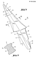
- Figur 4 eine Draufsicht auf einen Baggerzahn nach der Erfindung,
- Figur 5 eine Seitenansicht auf den Baggerzahn nach Figur 4,
- Figur 6 einen Schnitt gemäß der Linie VI-VI in Figur 4,
- Figur 7 einen Schnitt gemäß der Linie VII-VII in Figur 5,
- Figur 8 eine perspektivische Draufsicht auf die aus Sicherungslasche, Hülse, Kappe und Schraube bestehenden Befestigungsmittel für einen Baggerzahn nach Figur 4 und
- Figur 9 einen Baggerzahn gemäß der Erfindung in der Ausbildung als Spitzzahn.
- An den leicht nach innen geneigten Außenwandungen eines Schaufelradeimers 1 (Figur 1) eines hier nicht dargestellten Schaufelrades eines Schaufelradbaggers sind in vorliegendem Ausführungsbeispiel neun Baggerzähne B1 ) bis B9 auswechselbar angeordnet, von denen je drei Baggerzähne den zwei Seitenwandungen 2 und 3 und drei Baggerzähne der Brustwandung 4 des Eimers zugeordnet sind. Hierzu dienen mit den Außenwandungen des Eimers zur Oberkante K bündig verschweißte, im Querschnitt U-förmige Hülsen H1 bis H9, deren Innenwandungen 5, 6 und 7 mit den Außenflächen des Zahnschaftes des noch näher zu beschreibenden Baggerzahnes korrespondieren; vgl. auch Figur 8.
- Die Hülsen H sind, wie insbesondere die Figuren 1 und 3 zeigen, derart mit den Außenwandungen des Eimers verschweißt, daß sie, bezogen auf die Senkrechten S1 bis S9, jeweils unterschiedliche Neigungswinkel η 1 bis η 9 (etal bis eta9) aufweisen. Dementsprechend weisen auch die in die Hülsen H1 bis H9 einzusetzenden Baggerzähne B1 bis B9 unterschiedliche Neigungswinkel η (eta) auf. Werden unter Bezugnahme auf Figur 2 die den Seitenwandungen 2 und 3 zugeordneten Baggerzähne B4 und B6 als Eckzähne sowie die Baggerzähne B5 als Mittelzahn bezeichnet, so gilt, daß die Mittelachsen M des oder der in einer oder mehreren, den Eimer 1 zentrisch oder in gleichen Abständen senkrecht schneidenden Ebenen angeordneten Mittelzähne B5 senkrecht zur Oberkante des Eimers stehen, daß die Mittelachse M der in der die Brustwandung 4 des Eimers 1 enthaltenden Ebene angeordneten Eckzähne B4 und B6 mit der Oberkante des Eimers gleich große,aber entgegengesetzt gerichtete Neigungswinkel η4 und η6 (eta4 und eta6) einschließen, und daß die Mittelachsen M der in der die Seitenwandungen 2 und 3 des Eimers 1 einschließenden Ebene angeordneten Seitenzähne B1 bis B3 und B7 bis B9 mit der Oberkante K des Eimers 1 gleichgerichtete, aber unterschiedliche Neigungswinkel η 1 bis η 3 und η 7 bis η 9 (eta1 bis eta3 und eta7 bis eta9) einschließen.
- Wie Versuche gezeigt haben, betragen die Neigungswinkel η 4 und η 6 (eta4 und eta6) der Eckzähne B4 und B6 10° bis 20°, vorzugsweise aber 15°, während die Neigungswinkel η 1 bis η 3 (eta1 bis eta3) und η 9 bis η 7 (eta9 bis eta7) der Seitenzähne B1 bis B3 und B9 bis B7 von innen, das heißt vom nicht dargestellten Schaufelrad, also in bezug auf Figur 1 von links ausgehend, nach außen zur Brustwandung hin um jeweils 5° innerhalb eines Bereiches von 5° bis 20° zunehmen, so daß die Mittelachsen M in bezug auf die Senkrechten S1 bis S3 vorzugsweise eine Neigung von 5°, 10° und 15° aufweisen. Entsprechendes gilt auch für die den Senkrechten S bis S7 zugeordneten Mittelachsen M der in Figur 1 nicht sichtbaren Seitenzähne B7 bis B9.
- Um das Aufschweißen der Hülsen H bis H9 zu erleichtern, weisen die Seitenwandungen und Brustwandungen 2 bis 4 des Eimers 1 Anlageflächen auf.
- Nunmehr sei anhand der Figuren 4 bis 7 der unabhängig von seiner Verwendung als Seitenzahn, Eckzahn oder Mittelzahn jeweils gleich ausgebildete Baggerzahn B beschrieben.
- Der einstückig, vorzugsweise gesenkgeschmiedete Baggerzahn weist einen Zahnkeil 10 und einen Zahnschaft 11 auf, zwischen denen sich eine breit ausgebildete Wulst 12 befindet, die, sobald der Baggerzahn in die zugehörige Hülse H eingesteckt ist, eine Abdeckung für die Hülse bildet. Der Zahnschaft ist im Querschnitt ein ein unregelmäßiges Sechseck bildender Pyramidenstumpf mit zwei ebenen, einander gegenüberliegenden Flächen 14, 15, von denen die eine Fläche 14 die in bezug auf die Basis 36 des Pyramidenstumpfes senkrechte Anlagefläche 14 bildet, und die weiteren, jeweils paarweise einander gegenüberliegenden Flächen 16, 17 und 18, 19 des Pyramidenstumpfes einen Winkel k von etwa 168° einschließen. Die Fläche 15 weist einen Neigungswinkel 6 (delta) von 10° bis 14 c, insbesondere von 12°, auf.
- Der pyramidenförmige Zahnkeil 10 weist eine Zahnkeilunterseite 20 und eine Zahnkeiloberseite 21 auf; vgl. insbesondere Figur 5. Die Zahnkeilunterseite 20 weist, bezogen auf die Anlagefläche 14 des Baggerzahnes, eine Anhebung c (sigma) von 1° bis 3°, vorzugsweise von 2°, auf, während die Zahnkeiloberseite 21, bezogen auf diese Anlagefläche 14, eine Absenkung T (tau) von 20° bis 25°, vorzugsweise von 23°, aufweist. Die dazu im wesentlichen rechtwinkligen Zahnkeilflächen sind, wie insbesondere Figur 4 zeigt, leicht konkav gekrümmt. Der Keilwinkel ß (beta) des Zahnkeiles 10 beträgt 19° bis 22°, vorzugsweise 21°. Ferner ist der Zahnkeil 10 im Bereich unterhalb seiner Keilspitze 24 im Querschnitt etwa doppel-T-förmig ausgebildet, vgl. Figur 7, so daß sich Aussparungen 26 und 27 auf der Zahnkeiloberseite und der Zahnkeilunterseite 21 und 20 befinden, die sogenannte Selbstschärfeflächen sind.
- Schließlich weist die am Zahnschaft 11 befindliche Anlagefläche 14 des Baggerzahnes B einen im unteren Bereich befindlichen Nocken 30 auf, der von einer Sicherungslasche 31 umfaßt ist, die mit einem Schraubbolzen 32 durch das dem Baggerzahn B abgewandte Ende der Hülse H ragt und dort eine Kappe 34 trägt, welche mittels einer Mutter 35 gegenüber dem zugewandten Hülsenende 37 verspannbar ist; vgl. Figuren 1 und 8.
- Mit Hilfe der eben beschriebenen Befestigungsmittel läßt sich also der in die Hülse H eingesteckte Baggerzahn B auf einfache Weise festlegen, wie dies die Figuren 1 und 3 ebenfalls zeigen, wobei die Spannorgane etwa in der Mittelachse M liegen.
- Unter Berücksichtigung der Neigung der Wandungen des Schaufelradeimers 1 und der vorstehend beschriebenen Anhebung o (sigma) und Absenkung Υ (tau) der Zahnkeilflächen 20 und 21 des Zahnkeils weist jeder Baggerzahn B4 bis B6 nach seinem Verbinden mit dem Eimer einen Anstellwinkel a (alpha) im Bereich von 30° bis 50°, vorzugsweise von 43°, und einen Freiwinkel Y (gamma) in einem Bereich von 20° bis 28°, vorzugsweise von 23°, auf, während die mit der Seitenwandung 2, 3 lösbar verbundenen Baggerzähne B1 bis B3 und B7 und B9 einen Anstellwinkel a (alpha) im Bereich von 30° bis 50°, vorzugsweise 48°, und einen Freiwinkel Y (gamma) in einem Bereich von 20° bis 28°, vorzugsweise von 18°, aufweisen; vgl. Figur 1. Auf diese Weise erfolgt bei langen Standzeiten ein einwandfreies "Freischneiden" des Eimers und damit des Schaufelrades auch bei schwierigem Gebirge und bei Naßbaggerung.
- Bei Schaufelradeimern mit ebenen Wandungen ist es für bestimmte Einsatzfälle zweckmäßig alle Baggerzähne mit gleichen Freiwinkeln und Anstellwinkeln anzuordnen. Die Freiwinkel γ (gamma) betragen dann 2° bis 48°, vorzugsweise 26°, während die Anstellwinkel α (alpha) dann 20° bis 28°, vorzugsweise 23°, betragen.
- Da für verschiedene Anwendungszwecke sogenannte Spitzzähne erforderlich sind, zeigt die Figur 9 die Ausbildung des vorstehend beschriebenen Baggerzahnes B als Spitzzahn. Dementsprechend ist bei sonst gleicher Ausbildung, insbesondere des Zahnschaftes 11 und des Wulstes 12, der Zahnkeil 10 als an sich bekannter Spitzkeil ausgebildet, der in eine Spitze 24', anstelle der Schneide 24, ausläuft.
Claims (12)
Applications Claiming Priority (2)
| Application Number | Priority Date | Filing Date | Title |
|---|---|---|---|
| DE3444563 | 1984-12-06 | ||
| DE19843444563 DE3444563A1 (de) | 1984-12-06 | 1984-12-06 | Baggerzahn-anordnung |
Publications (2)
| Publication Number | Publication Date |
|---|---|
| EP0184209A1 true EP0184209A1 (de) | 1986-06-11 |
| EP0184209B1 EP0184209B1 (de) | 1989-03-29 |
Family
ID=6252089
Family Applications (1)
| Application Number | Title | Priority Date | Filing Date |
|---|---|---|---|
| EP85115478A Expired EP0184209B1 (de) | 1984-12-06 | 1985-12-05 | Baggerzahn-Anordnung |
Country Status (10)
| Country | Link |
|---|---|
| US (1) | US4642920A (de) |
| EP (1) | EP0184209B1 (de) |
| JP (1) | JPH0651983B2 (de) |
| CN (1) | CN1006405B (de) |
| AU (1) | AU582512B2 (de) |
| BR (1) | BR8506287A (de) |
| CA (1) | CA1248997A (de) |
| DE (2) | DE3444563A1 (de) |
| ES (1) | ES296768Y (de) |
| ZA (1) | ZA859332B (de) |
Cited By (2)
| Publication number | Priority date | Publication date | Assignee | Title |
|---|---|---|---|---|
| EP0259297A1 (de) * | 1986-09-02 | 1988-03-09 | VOEST-ALPINE Aktiengesellschaft | Baggerzahn |
| EP0280003A1 (de) * | 1986-01-21 | 1988-08-31 | Santrade Limited | Vorrichtung in einem Schaufelrad |
Families Citing this family (29)
| Publication number | Priority date | Publication date | Assignee | Title |
|---|---|---|---|---|
| US5018283A (en) * | 1989-08-04 | 1991-05-28 | Deere & Company | Loader bucket tooth |
| US4949481A (en) * | 1989-08-04 | 1990-08-21 | Deere & Company | Digging tooth assembly |
| US5653048A (en) | 1995-11-06 | 1997-08-05 | Esco Corporation | Wear assembly for a digging edge of an excavator |
| US5782019A (en) * | 1995-11-29 | 1998-07-21 | H & L Tooth Company | High strength earth working tooth |
| USD399511S (en) | 1995-11-29 | 1998-10-13 | H & L Tooth Company | Digging tooth |
| US20040045742A1 (en) * | 2001-04-10 | 2004-03-11 | Halliburton Energy Services, Inc. | Force-balanced roller-cone bits, systems, drilling methods, and design methods |
| AUPR803401A0 (en) * | 2001-10-02 | 2001-10-25 | Meyers, Thomas Anthony | Excavator teeth |
| US8438760B2 (en) * | 2002-03-26 | 2013-05-14 | Sandvik Mining And Construction Australia (Production/Supply) Pty Ltd. | Mechanical attachment system and associated failure mechanism |
| AUPS134802A0 (en) * | 2002-03-26 | 2002-05-09 | Shark Abrasion Systems Pty Ltd | Attachment system |
| US6848203B2 (en) * | 2002-08-19 | 2005-02-01 | Caterpillar Inc | Base edge protection system and method |
| US7739815B2 (en) * | 2003-01-23 | 2010-06-22 | Horton Lee A | Ripper excavation tool |
| SE524301C2 (sv) * | 2003-07-11 | 2004-07-20 | Combi Wear Parts Ab | Tandsystem |
| US7114272B2 (en) * | 2003-09-09 | 2006-10-03 | H&L Tooth Company | Winged digging tooth |
| USD527029S1 (en) | 2004-06-14 | 2006-08-22 | H&L Tooth Company | Ground engaging tooth |
| MX2009002088A (es) * | 2006-09-01 | 2009-08-31 | Metalogenia Sa | Diente y adaptador para maquina de dragado. |
| US7921581B2 (en) * | 2006-11-23 | 2011-04-12 | J. Muller Ag, Maschineller Geleiseunterhalt | Excavation device |
| US8061064B2 (en) | 2007-05-10 | 2011-11-22 | Esco Corporation | Wear assembly for excavating equipment |
| EP1997967B1 (de) * | 2007-06-01 | 2010-05-12 | IHC Holland IE B.V. | Zahnsystem |
| JP5362074B2 (ja) * | 2012-05-29 | 2013-12-11 | 株式会社小松製作所 | 建設機械の掘削バケット |
| JP5318993B1 (ja) * | 2012-05-29 | 2013-10-16 | 株式会社小松製作所 | 建設機械の掘削バケット |
| DE102012111842A1 (de) | 2012-12-05 | 2014-06-05 | Thyssenkrupp Resource Technologies Gmbh | Zahn für eine Schaufel, insbesondere für einen Schaufelradbagger |
| DE102013102407B4 (de) * | 2013-03-11 | 2021-12-30 | Thyssenkrupp Industrial Solutions Ag | Schaufelrad zum Abbau von Materialien aus einem Materialverband hoher Härte |
| US9404240B2 (en) | 2013-11-07 | 2016-08-02 | Caterpillar Inc. | Bucket lip protection assemblies and lip adapters for same |
| NL2015612B1 (en) * | 2015-10-14 | 2017-05-08 | Ihc Holland Ie Bv | Snail tooth. |
| EP3358089A1 (de) | 2017-02-07 | 2018-08-08 | Leo Dynamische Investering B.V. | Schneidkopf und zahnsystem |
| US10208452B2 (en) * | 2017-03-22 | 2019-02-19 | Caterpillar Inc. | Bucket for implement system having symmetrical tooth mounting members |
| CN107806004B (zh) * | 2017-11-28 | 2023-08-22 | 佛山科学技术学院 | 一种市政工程用的沥青铲除板 |
| DE102018203913A1 (de) | 2018-03-14 | 2019-09-19 | Thyssenkrupp Ag | Aufnahmeanordnung eines Baggerzahnes mit einer Aufnahme zur Anordnung an der Schaufel eines Schaufelradbaggers |
| US12553342B2 (en) * | 2022-08-02 | 2026-02-17 | Kennametal Inc. | Cutter tooth assembly for an excavating tool |
Citations (9)
| Publication number | Priority date | Publication date | Assignee | Title |
|---|---|---|---|---|
| US2397521A (en) * | 1944-09-01 | 1946-04-02 | Cleveland Trencher Co | Rooter for excavators |
| GB897280A (en) * | 1960-10-28 | 1962-05-23 | Cleveland Trencher Co | Digger tooth for earth and mineral-excavating machines |
| US3280486A (en) * | 1964-10-19 | 1966-10-25 | Atlantic Richfield Co | Ripper tooth for bucket diggers and the like |
| DE2039407A1 (de) * | 1969-08-08 | 1971-02-25 | Kopalnia Wegla Brunatnego Adam | Schaufel fuer Schaufelradbagger |
| US3606471A (en) * | 1969-03-25 | 1971-09-20 | Jetco Inc | Trenching devices |
| DE2114498A1 (de) * | 1971-03-25 | 1972-10-05 | Aulfinger, Andre, 7257 Ditzingen | Bagger- oder "Schaufelzahn |
| FR2189590A1 (de) * | 1972-06-15 | 1974-01-25 | Great Canadian Oil Sands | |
| US3897642A (en) * | 1974-05-13 | 1975-08-05 | Caterpillar Tractor Co | Earth working tip and adapter construction |
| DE3031496A1 (de) * | 1980-08-21 | 1982-03-25 | Wallram Hartmetall Gmbh, 4300 Essen | Schaufelradbagger |
Family Cites Families (15)
| Publication number | Priority date | Publication date | Assignee | Title |
|---|---|---|---|---|
| US1519101A (en) * | 1924-01-14 | 1924-12-16 | Erie Steam Shovel Company | Excavating device |
| US2385395A (en) * | 1944-02-11 | 1945-09-25 | Electric Steel Foundry | Excavating tooth |
| US2740212A (en) * | 1955-09-30 | 1956-04-03 | Dwight E Werkheiser | Rooter tooth assembly |
| US3091044A (en) * | 1960-10-28 | 1963-05-28 | Cleveland Trencher Co | Digger tooth |
| US3371437A (en) * | 1965-04-28 | 1968-03-05 | Mid Continent Steel Casting Co | Locking device for digger tooth |
| DE7045807U (de) * | 1970-12-11 | 1972-01-27 | Lehnhoff Hartstahl Kg | Hulsenhalterung fur Baggerschaufel zahne |
| IT1005056B (it) * | 1971-12-20 | 1976-08-20 | Italricambi Di F Quoco E C | Perfezionamenti ai denti per benne di macchine per movimento terre e e denti derivati |
| FR2264140A1 (en) * | 1974-03-15 | 1975-10-10 | Garcia Roger | Tooth support for an excavator bucket - has tooth point and adaptor abutting on only three faces |
| FR2277944A1 (fr) * | 1974-07-08 | 1976-02-06 | Bofors Ab | Element rapporte de fixation des dents d'une pelle excavatrice |
| US3919792A (en) * | 1974-11-25 | 1975-11-18 | Esco Corp | Excavating tooth assembly |
| SU606934A1 (ru) * | 1976-05-11 | 1978-05-15 | Всесоюзный Научно-Исследовательский И Проектный Институт Угольной Промышленности "Укрниипроект" | Рабочий орган роторного эскаватора |
| US4360981A (en) * | 1977-12-12 | 1982-11-30 | Suncor Inc. | Lip and tooth combination for bucket wheel excavator |
| US4516339A (en) * | 1979-10-17 | 1985-05-14 | Gh Hensley Industries, Inc. | Combination excavating bucket, shank and digging teeth |
| JPS5812424A (ja) * | 1981-07-15 | 1983-01-24 | Toko Inc | 逐次比較型a/d変換器 |
| DE3442747A1 (de) * | 1984-11-23 | 1986-05-28 | Berchem & Schaberg Gmbh, 4650 Gelsenkirchen | Aus zahn und adapter bestehender werkzeugsatz |
-
1984
- 1984-12-06 DE DE19843444563 patent/DE3444563A1/de active Granted
-
1985
- 1985-12-04 CN CN85108788A patent/CN1006405B/zh not_active Expired
- 1985-12-05 JP JP60272643A patent/JPH0651983B2/ja not_active Expired - Fee Related
- 1985-12-05 CA CA000496990A patent/CA1248997A/en not_active Expired
- 1985-12-05 EP EP85115478A patent/EP0184209B1/de not_active Expired
- 1985-12-05 ES ES1985296768U patent/ES296768Y/es not_active Expired
- 1985-12-05 DE DE8585115478T patent/DE3569139D1/de not_active Expired
- 1985-12-05 ZA ZA859332A patent/ZA859332B/xx unknown
- 1985-12-05 AU AU50798/85A patent/AU582512B2/en not_active Ceased
- 1985-12-06 BR BR8506287A patent/BR8506287A/pt not_active IP Right Cessation
- 1985-12-06 US US06/805,890 patent/US4642920A/en not_active Expired - Lifetime
Patent Citations (9)
| Publication number | Priority date | Publication date | Assignee | Title |
|---|---|---|---|---|
| US2397521A (en) * | 1944-09-01 | 1946-04-02 | Cleveland Trencher Co | Rooter for excavators |
| GB897280A (en) * | 1960-10-28 | 1962-05-23 | Cleveland Trencher Co | Digger tooth for earth and mineral-excavating machines |
| US3280486A (en) * | 1964-10-19 | 1966-10-25 | Atlantic Richfield Co | Ripper tooth for bucket diggers and the like |
| US3606471A (en) * | 1969-03-25 | 1971-09-20 | Jetco Inc | Trenching devices |
| DE2039407A1 (de) * | 1969-08-08 | 1971-02-25 | Kopalnia Wegla Brunatnego Adam | Schaufel fuer Schaufelradbagger |
| DE2114498A1 (de) * | 1971-03-25 | 1972-10-05 | Aulfinger, Andre, 7257 Ditzingen | Bagger- oder "Schaufelzahn |
| FR2189590A1 (de) * | 1972-06-15 | 1974-01-25 | Great Canadian Oil Sands | |
| US3897642A (en) * | 1974-05-13 | 1975-08-05 | Caterpillar Tractor Co | Earth working tip and adapter construction |
| DE3031496A1 (de) * | 1980-08-21 | 1982-03-25 | Wallram Hartmetall Gmbh, 4300 Essen | Schaufelradbagger |
Cited By (2)
| Publication number | Priority date | Publication date | Assignee | Title |
|---|---|---|---|---|
| EP0280003A1 (de) * | 1986-01-21 | 1988-08-31 | Santrade Limited | Vorrichtung in einem Schaufelrad |
| EP0259297A1 (de) * | 1986-09-02 | 1988-03-09 | VOEST-ALPINE Aktiengesellschaft | Baggerzahn |
Also Published As
| Publication number | Publication date |
|---|---|
| ZA859332B (en) | 1986-08-27 |
| US4642920A (en) | 1987-02-17 |
| JPH0651983B2 (ja) | 1994-07-06 |
| ES296768Y (es) | 1988-10-01 |
| BR8506287A (pt) | 1986-08-26 |
| CN85108788A (zh) | 1986-06-10 |
| DE3444563C2 (de) | 1993-09-16 |
| DE3444563A1 (de) | 1986-06-19 |
| CA1248997A (en) | 1989-01-17 |
| ES296768U (es) | 1988-01-16 |
| EP0184209B1 (de) | 1989-03-29 |
| DE3569139D1 (en) | 1989-05-03 |
| JPS61137931A (ja) | 1986-06-25 |
| CN1006405B (zh) | 1990-01-10 |
| AU5079885A (en) | 1986-06-12 |
| AU582512B2 (en) | 1989-03-23 |
Similar Documents
| Publication | Publication Date | Title |
|---|---|---|
| EP0184209B1 (de) | Baggerzahn-Anordnung | |
| DE2602744A1 (de) | Zahn fuer baggerloeffel von erdbewegungsmaschinen | |
| DE2140111A1 (de) | Zweiteilige Schaufelkante für Flachbagger od. dgl | |
| EP0317692A1 (de) | Stopfpickel für Gleisstopfmaschinen | |
| DE2851442A1 (de) | Baggerschaufel | |
| DE1295579B (de) | Vorrichtung zum UEberbruecken von Dehnungsfugen, insbesondere in Bruecken | |
| DE9305835U1 (de) | Schneidkörper für den Schlegel eines umlaufenden Schlagwerkes | |
| DE3600105A1 (de) | Zahnaerztliche reibahle | |
| DE2004922A1 (de) | Erdbearbeitungswerkzeug | |
| DE2644992A1 (de) | Fraesvorrichtung, insbesondere zum abfraesen von strassenbelaegen | |
| DE19547170C2 (de) | Fräswalze für ein in beiden Fahrtrichtungen Gewinnungsarbeit leistendes Tagebaugewinnungsgerät | |
| DE7806211U1 (de) | Bohrwerkzeug fuer bohrungen in metallvollmaterial von werkstuecken | |
| DE4002907C2 (de) | ||
| DE8715141U1 (de) | Fräswerkzeug zur Erdbearbeitung | |
| DE3408093A1 (de) | Bohrkrone | |
| DE2605211C3 (de) | Zweiteiliger Baggerzahn | |
| DE3442747A1 (de) | Aus zahn und adapter bestehender werkzeugsatz | |
| EP0232468B1 (de) | Schneidkopfzahn | |
| DE2744497B2 (de) | Schaufelzahn für Bagger o.dgl | |
| EP0260643A2 (de) | Vertikutiermesser für ein Vertikutiergerät | |
| DE3100765A1 (de) | Verschleissschutz fuer die schaufelarme von mischern, insbesondere betonmischern | |
| DE2855577A1 (de) | Fraesmeissel fuer eine fraes- oder schraemmeinrichtung | |
| DE3619334A1 (de) | Hohlbohrkrone | |
| EP0223896A2 (de) | Schneidkettenglied einer Schrämkette | |
| DE4226363C2 (de) | Bohrkrone mit umfangverteilten, lösbar angeordneten Zahnkörpern |
Legal Events
| Date | Code | Title | Description |
|---|---|---|---|
| PUAI | Public reference made under article 153(3) epc to a published international application that has entered the european phase |
Free format text: ORIGINAL CODE: 0009012 |
|
| AK | Designated contracting states |
Kind code of ref document: A1 Designated state(s): BE DE FR GB IT NL SE |
|
| 17P | Request for examination filed |
Effective date: 19860715 |
|
| 17Q | First examination report despatched |
Effective date: 19870611 |
|
| GRAA | (expected) grant |
Free format text: ORIGINAL CODE: 0009210 |
|
| AK | Designated contracting states |
Kind code of ref document: B1 Designated state(s): BE DE FR GB IT NL SE |
|
| PG25 | Lapsed in a contracting state [announced via postgrant information from national office to epo] |
Ref country code: SE Effective date: 19890329 Ref country code: IT Free format text: LAPSE BECAUSE OF FAILURE TO SUBMIT A TRANSLATION OF THE DESCRIPTION OR TO PAY THE FEE WITHIN THE PRESCRIBED TIME-LIMIT;WARNING: LAPSES OF ITALIAN PATENTS WITH EFFECTIVE DATE BEFORE 2007 MAY HAVE OCCURRED AT ANY TIME BEFORE 2007. THE CORRECT EFFECTIVE DATE MAY BE DIFFERENT FROM THE ONE RECORDED. Effective date: 19890329 |
|
| GBT | Gb: translation of ep patent filed (gb section 77(6)(a)/1977) | ||
| REF | Corresponds to: |
Ref document number: 3569139 Country of ref document: DE Date of ref document: 19890503 |
|
| ET | Fr: translation filed | ||
| PLBI | Opposition filed |
Free format text: ORIGINAL CODE: 0009260 |
|
| 26 | Opposition filed |
Opponent name: KRUPP INDUSTRIETECHNIK GMBH Effective date: 19891223 |
|
| NLR1 | Nl: opposition has been filed with the epo |
Opponent name: KRUPP INDUSTRIETECHNIK GMBH. |
|
| PLBN | Opposition rejected |
Free format text: ORIGINAL CODE: 0009273 |
|
| STAA | Information on the status of an ep patent application or granted ep patent |
Free format text: STATUS: OPPOSITION REJECTED |
|
| 27O | Opposition rejected |
Effective date: 19910621 |
|
| NLR2 | Nl: decision of opposition | ||
| REG | Reference to a national code |
Ref country code: GB Ref legal event code: IF02 |
|
| PGFP | Annual fee paid to national office [announced via postgrant information from national office to epo] |
Ref country code: GB Payment date: 20021015 Year of fee payment: 18 |
|
| PGFP | Annual fee paid to national office [announced via postgrant information from national office to epo] |
Ref country code: NL Payment date: 20021021 Year of fee payment: 18 |
|
| PGFP | Annual fee paid to national office [announced via postgrant information from national office to epo] |
Ref country code: BE Payment date: 20021112 Year of fee payment: 18 |
|
| PGFP | Annual fee paid to national office [announced via postgrant information from national office to epo] |
Ref country code: FR Payment date: 20021210 Year of fee payment: 18 |
|
| PGFP | Annual fee paid to national office [announced via postgrant information from national office to epo] |
Ref country code: DE Payment date: 20021220 Year of fee payment: 18 |
|
| PG25 | Lapsed in a contracting state [announced via postgrant information from national office to epo] |
Ref country code: GB Free format text: LAPSE BECAUSE OF NON-PAYMENT OF DUE FEES Effective date: 20031205 |
|
| PG25 | Lapsed in a contracting state [announced via postgrant information from national office to epo] |
Ref country code: BE Free format text: LAPSE BECAUSE OF NON-PAYMENT OF DUE FEES Effective date: 20031231 |
|
| BERE | Be: lapsed |
Owner name: *LEHNHOFF HARTSTAHL G.M.B.H. & CO. Effective date: 20031231 |
|
| PG25 | Lapsed in a contracting state [announced via postgrant information from national office to epo] |
Ref country code: NL Free format text: LAPSE BECAUSE OF NON-PAYMENT OF DUE FEES Effective date: 20040701 Ref country code: DE Free format text: LAPSE BECAUSE OF NON-PAYMENT OF DUE FEES Effective date: 20040701 |
|
| GBPC | Gb: european patent ceased through non-payment of renewal fee |
Effective date: 20031205 |
|
| PG25 | Lapsed in a contracting state [announced via postgrant information from national office to epo] |
Ref country code: FR Free format text: LAPSE BECAUSE OF NON-PAYMENT OF DUE FEES Effective date: 20040831 |
|
| NLV4 | Nl: lapsed or anulled due to non-payment of the annual fee |
Effective date: 20040701 |
|
| REG | Reference to a national code |
Ref country code: FR Ref legal event code: ST |
|
| APAH | Appeal reference modified |
Free format text: ORIGINAL CODE: EPIDOSCREFNO |