EP0184246A2 - Elektronischer Farbsignalgenerator und Farbbildanzeigesystem mit diesem Generator - Google Patents
Elektronischer Farbsignalgenerator und Farbbildanzeigesystem mit diesem Generator Download PDFInfo
- Publication number
- EP0184246A2 EP0184246A2 EP19850201854 EP85201854A EP0184246A2 EP 0184246 A2 EP0184246 A2 EP 0184246A2 EP 19850201854 EP19850201854 EP 19850201854 EP 85201854 A EP85201854 A EP 85201854A EP 0184246 A2 EP0184246 A2 EP 0184246A2
- Authority
- EP
- European Patent Office
- Prior art keywords
- colour
- memory
- address
- reference data
- intensity
- Prior art date
- Legal status (The legal status is an assumption and is not a legal conclusion. Google has not performed a legal analysis and makes no representation as to the accuracy of the status listed.)
- Withdrawn
Links
Images
Classifications
-
- G—PHYSICS
- G09—EDUCATION; CRYPTOGRAPHY; DISPLAY; ADVERTISING; SEALS
- G09G—ARRANGEMENTS OR CIRCUITS FOR CONTROL OF INDICATING DEVICES USING STATIC MEANS TO PRESENT VARIABLE INFORMATION
- G09G5/00—Control arrangements or circuits for visual indicators common to cathode-ray tube indicators and other visual indicators
- G09G5/02—Control arrangements or circuits for visual indicators common to cathode-ray tube indicators and other visual indicators characterised by the way in which colour is displayed
- G09G5/06—Control arrangements or circuits for visual indicators common to cathode-ray tube indicators and other visual indicators characterised by the way in which colour is displayed using colour palettes, e.g. look-up tables
Definitions
- the invention relates to an electronic colour signal generator for a colour image display system, which generator comprises a memory having addressable memory locations for storing colour reference data, an address generator connected to an address input of the memory and having a signal input for receiving digital signals representing pixels to be displayed, said address generator being provided for generating address words for selectively addressing the memory locations, a generated address word comprising a first part determined upon a receipt digital signal, reading means connected to a data output of the memory for outputting the colour reference data from the selected memory locations.
- Such an electronic colour signal generator is known from the GB patent specification GB 2 032 740A.
- the colour reference data stored in the memory identifies different colours of varying hue, saturation and intensity.
- hue means the attribute of colours that permits them to be classified as red, green, blue, or an intermediate between any contiguous pair of these three colours, and relates to the dominant wavelength of a colour.
- saturation characterises the purity of a colour, that is, the extent to which it is mixed with white.
- “Intensity” relates to the brightness or luminosity of a colour.
- the stored colour reference data is in three separate parts which relate respectively to linear proportions of the three primary colours, red, green and blue that are to be combined to produce that particular colour of appropriate hue, saturation and intensity on a display unit of a colour image system.
- a digital signal representing that pixel colour is supplied to a signal input of the address generator.
- the address generator Upon a receipt digital signal the address generator generates an address word for selecting a memory location in the memory. At that selected memory location there is stored colour reference data for that particular colour which colour reference data is then outputted via the reading means, and supplied to a display unit for displaying that particular pixel in that particular colour.
- a drawback of the known electronic colour signal generator is that for different intensity values of a same colour, either the same colour reference data have to be used, or it is necessary to reprogram the memory, which is a roundabout way of operating the system.
- the colour characteristics of hue, saturation and intensity are not simple functions of the red, green and blue colour proportions, but are extremely inter-dependent and are interrelated by complex mathematical formulae. These relationships are further complicated by the non-linear response or "gamma" of a cathode ray tube. Therefore, it has been found that the intensity of many colours is unlikely to be altered by a linear change in the proportions of red, green and blue colours which are used additively to produce them, without also changing the hue and saturation of these colours.
- a colour signal generator of the type set forth above is characterized in that said address generator comprises an intensity signal input for receiving an intensity value indicating the pixel display intensity, said address generator being further provided for generating an exclusive second address part for each received intensity value and for forming address words by combining for each pixel their respective first and second address part, and wherein said memory comprises a number (N ⁇ 2) of memory sections, each memory section being assigned for the storage of exclusive colour reference data, a memory section being selectable by one of said address parts and a location within the selected memory section being selectable by the other address part.
- each section comprises exclusive colour reference data
- each section comprises exclusive colour reference data
- each section comprises exclusive colour reference data
- colour reference data for higher and/or lower intensity versions of the standard range of colours to be stored in another section or sections of the memory. It is thus no longer necessary to reprogram the memory to obtain another set of colour reference data.
- the address generator Upon receipt of an intensity value on his intensity signal input, the address generator generates an exclusive second address part for this intensity value. An address word for a pixel is then formed by combining the first and the second address part. Thus for a particular combination of colour and intensity there is formed an exclusive address word, which addresses an exclusive colour reference data.
- One of said address parts selects a memory section while the other address part then selects a colour reference data in that selected memory section. That exclusive colour reference data than permits to display the pixel in the desired combination of colour and intensity without affecting the hue and saturation.
- prior USA patent specification 4 183 046 describes a colour signal generator in which the words of the first digital signal are in three separate groups of data bits which define the colours of elements of an image to be displayed in terms of intensity, hue and saturation.
- the data bit groups corresponding to hue and saturation are employed for simultaneously addressing the memory which contains colour reference data representing the dimensions of hue and saturation only.
- This data is read out as a second digital signal for conversion by digital-to-analogue conversion means into analogue signals which serve as red, green and blue video signals for driving a 3- gun colour cathode ray tube to form on the screen thereof the image represented by the first digital signal.
- the data bit group which corresponds to intensity is applied to the digital-to-analogue conversion means to modulate the magnitude of the red, green and blue video signals. This permits intensity to be altered without also altering hue and/or saturation.
- a first preferred embodiment of a colour image display apparatus comprising a colour signal generator according to the invention is characterized in that each of said memory sections having at least a predetermined number of memory locations, each of said memory sections being assigned for the storage of colour reference data belonging to a particular intensity value, a memory section being selectable by said second address part while a location within a selected memory section being selectable by said first address part.
- the predetermined number of memory locations of each memory section is given by the minimum number of different colour available in the colour image display system. In this particular embodiment there is one memory section per intensity level.
- a second preferred embodiment of a colour image display apparatus comprising a colour signal generator according to the invention is characterized in that each of said memory sections having at least a predetermined number of memory locations, each of said memory sections being assigned for the storage of colour reference data of different intensities belonging to a particular colour, a memory section being selectable by said first address part while a location within a selected memory section being selectable by said second address part.
- each of said memory sections having at least a predetermined number of memory locations, each of said memory sections being assigned for the storage of colour reference data of different intensities belonging to a particular colour, a memory section being selectable by said first address part while a location within a selected memory section being selectable by said second address part.
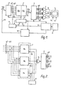
- the image display system shown in Figure 1 comprises a colour signal generator which is formed by a colour memory 1, a memory addressing circuit 2, a memory read-out circuit 3, and a select circuit 11.
- the image display system further comprises three digital-to-analogue converters 4, 5 and 6, a colour cathode ray tube display device 7, a processor 8, an input device 9, a display memory 10, and a timing control circuit 12.
- the input device 9 can be, for instance, an electronic writing tablet for creating static colour pictures and other graphics displays on the screen of the display device 7.
- the created display is in bit-map form and may be composed, for instance, of a matrix of 512 x 512 picture elements (pixels).
- the colour of each pixel of an image display is stored as a multi-bit word in the display memory 10, which is a random access memory. It is assumed for the purpose of discussion that each pixel can have any one of sixteen different colours, so that each pixel is then represented by a respective 4-bit word in the display memory 10.
- the display device 7 is controlled by means of line and field synchronizing signals LS and FS to effect conventional refresh raster scanning (with or without field interlacing) for producing the image display.
- the 4-bit words which define the colours for the pixels of the image display are read out from the display memory 10.
- the four bits of each word are read out serially on a lead 13 for application to the memory addressing circuit 2 as a first digital signal 1DS.
- the circuit 2 latches the four bits of each received word in turn and applies them in parallel to the first four leads a1 to a4 of a group of five memory address leads a1 to a5.
- the remaining address lead a5 receives a logic "0" or "1" bit from the select circuit 11, as will be described.
- the colour memory 1 is a read only memory or a random access memory and serves as a colour look-up table (CLUT).
- the colour memory 1 has a first section M1 which comprises sixteen memory locations which can be addressed selectively by respective "0" and “1” bit combinations of the 4-bit words on the address leads A 1 to a4, in conjunction with a bit of value "0" on the address lead a5.
- the colour memory 1 also has a second section M2 which comprises sixteen memory locations which can be addressed selectively by the same respective "0” and “1” bit combinations of the 4-bit words on the address leads a1 to a4, in conjunction with a bit of value "1" on the address lead a5.
- Each of the memory locations of each section is assumed to have a storage capacity for a 12-bit word which represents colour reference data.
- a selection of sixteen different 12-bit words from a possible total of 4096 (-4K) 12-bit words can be stored in each memory section.
- the bits of the 12-bit word stored therein are read-out serially on a lead 14 as a second digital signal 2DS and latched into the memory read-out circuit 3.
- the bits of the latched word are then applied in three 4-bit groups to the digital-to-analogue converters 4, 5 and 6, respectively, over three groups of address leads A R, aG and aB. These converters convert the 4-bit groups applied them into respective red, green and blue video signals on leads R,G,B, for driving the colour cathode ray tube display device 7.
- the colour reference data stored in the sixteen memory locations of the memory section M1 represents a standard range of 16 different colours. These locations can be addressed by the appropriate 4- bit word on the address leads a1 to a4, as aforesaid.
- the colour reference data stored in the sixteen memory locations of the memory section m2 represent different (e.g. low) intensity versions of the 16 colours which form the standard range of colours.
- Each 4-bit word on the leads a1 to a4 also addresses in the memory sections M2 the particular memory location containing the different intensity version of the standard colour that is contained in the memory location which it addressed in the memory section M1.
- the select circuit 11 produces either a "0" bit or a "1" bit on the address lead a5, to select either the memory location in the memory section M1 or the memory location in the memory section M2, that are both being addressed by the 4-bit word on the address leads a1 to a4.
- the colour reference data is read out from the selected memory location to provide the standard or different colour version, as the case may be, for the pixel concerned in the image display.
- the selection among standard or different intensity versions of the colours can be realized either under request of an operator by application of a select signal at said input device 9, or under request of an executed program.
- the processor 8 supplies the coordinates of a display area together with an intensity value indicating the pixel display intensity (standard or different intensity) to the select circuit 11.
- This select circuit which also receives clock signals from the timing control circuit 12 scans with the displayed picture and applies either a "0" bit or a "1" bit on the address lead a5 in accordance with the received intensity indication when said colour memory is addressed for the display of said display area.
- a picture displayed on said display device 7 can be divided into, for example, 16 rectangular display areas numbered from 0-15.
- the processor 8 supplies the number (4 bits) of the display area and the associated intensity indication (1 bit) to the selection circuit.
- a content addressable memory is used which is loaded by the processor 8.
- the colour reference data in the colour memory 1 would be edited visually on the display device 7 using the processor 8 with an inter-active software program.
- the bit values of the three 4-bit groups for each colour forming the standard range of colours would first be settled by the user and then stored in the memory locations in the memory sections M1.
- the different intensity version of each colour would be settled subjectively by the user by altering the bit values of the three 4-bit groups for the colour until a satisfactory result was obtained.
- the altered bit values of the 4-bit groups for each colour would then be stored in the memory locations in the memory section M2.
- the timing of the operation of the colour signal generator is under the control of the timing control circuit 12.
- the timing control assumes serial read-out from both of the memories 1 and 10.
- data read-out in parallel from these memories would, of course, be possible by suitably altering the timing control.
- the colour memory 1 can have a number (N)2) of sections. For instance, three memory sections may be provided, the additional memory section containing colour reference data for high intensity versions of the standard range of colours. Where three memory sections of the colour memory 1 are provided, one additional address lead such as lead a5 would be required to provide a 2-bit select code from the select circuit 11.
- the colour memory 1 comprises three separate sections, Ma, Mb and Me to which the four address leads a1 to a4 are connected in common.
- Each of these separate sections contains sixteen memory locations and colour reference data for standard, high and low intensity versions of a range of 16 colours are stored in corresponding memory locations of the three memory sections.
- the select circuit 11 now has separate select leads S1 to S3 which are connected respectively to the separate sections Ma, Mb and Mc.
- each memory section comprises all the colour reference data for a particular intensity. It will be clear that other divisions of the memory 1 are also possible, such as for example a division wherein there is assigned a particular colour to each memory section. At the memory location of such a section there are then stored the colour reference data for the different intensities of that colour.
- the first part of the address word formed by the bits a1 to a4 then selects a memory section, while the second part (a5, or S1 to S3) selects a memory location within the selected memory section.
Landscapes
- Engineering & Computer Science (AREA)
- Physics & Mathematics (AREA)
- Computer Hardware Design (AREA)
- General Physics & Mathematics (AREA)
- Theoretical Computer Science (AREA)
- Controls And Circuits For Display Device (AREA)
- Processing Of Color Television Signals (AREA)
- Digital Computer Display Output (AREA)
Applications Claiming Priority (2)
| Application Number | Priority Date | Filing Date | Title |
|---|---|---|---|
| GB8429801 | 1984-11-26 | ||
| GB08429801A GB2167926A (en) | 1984-11-26 | 1984-11-26 | Colour signal generator for crt image display |
Publications (1)
| Publication Number | Publication Date |
|---|---|
| EP0184246A2 true EP0184246A2 (de) | 1986-06-11 |
Family
ID=10570265
Family Applications (1)
| Application Number | Title | Priority Date | Filing Date |
|---|---|---|---|
| EP19850201854 Withdrawn EP0184246A2 (de) | 1984-11-26 | 1985-11-12 | Elektronischer Farbsignalgenerator und Farbbildanzeigesystem mit diesem Generator |
Country Status (3)
| Country | Link |
|---|---|
| EP (1) | EP0184246A2 (de) |
| JP (1) | JPS61132995A (de) |
| GB (1) | GB2167926A (de) |
Cited By (5)
| Publication number | Priority date | Publication date | Assignee | Title |
|---|---|---|---|---|
| EP0258947A3 (de) * | 1986-09-02 | 1990-10-17 | North American Philips Corporation | Videomonitor-Schnittstelle für digitale Farbsignale |
| EP0457297A3 (en) * | 1990-05-16 | 1992-11-19 | Sanyo Electric Co., Ltd. | Display apparatus |
| GB2271493A (en) * | 1992-10-02 | 1994-04-13 | Canon Res Ct Europe Ltd | Processing colour image data |
| EP0921498A3 (de) * | 1997-12-08 | 2000-07-12 | Sony Corporation | Vorrichtung zur Datenumwandlung und Bilderzeugung |
| US6624822B2 (en) | 1997-12-08 | 2003-09-23 | Sony Corporation | Data conversion apparatus and image generation apparatus |
Families Citing this family (13)
| Publication number | Priority date | Publication date | Assignee | Title |
|---|---|---|---|---|
| JP2572373B2 (ja) * | 1986-01-14 | 1997-01-16 | 株式会社 アスキ− | カラ−デイスプレイ装置 |
| US4931785A (en) * | 1986-06-17 | 1990-06-05 | Ascii Corporation | Display apparatus |
| US5140312A (en) * | 1986-06-17 | 1992-08-18 | Ascii Corporation | Display apparatus |
| US4942388A (en) * | 1986-09-02 | 1990-07-17 | Grumman Aerospace Corporation | Real time color display |
| US4772881A (en) * | 1986-10-27 | 1988-09-20 | Silicon Graphics, Inc. | Pixel mapping apparatus for color graphics display |
| US5086295A (en) * | 1988-01-12 | 1992-02-04 | Boettcher Eric R | Apparatus for increasing color and spatial resolutions of a raster graphics system |
| JPH01248188A (ja) * | 1988-03-30 | 1989-10-03 | Toshiba Corp | 表示属性変換制御装置 |
| JPH01248187A (ja) * | 1988-03-30 | 1989-10-03 | Toshiba Corp | ディスプレイシステム |
| JPH01248186A (ja) * | 1988-03-30 | 1989-10-03 | Toshiba Corp | 表示属性変換装置 |
| US5124688A (en) * | 1990-05-07 | 1992-06-23 | Mass Microsystems | Method and apparatus for converting digital YUV video signals to RGB video signals |
| US5847700A (en) * | 1991-06-14 | 1998-12-08 | Silicon Graphics, Inc. | Integrated apparatus for displaying a plurality of modes of color information on a computer output display |
| GB2270450B (en) * | 1992-09-08 | 1997-03-26 | Silicon Graphics Incorporation | Integrated apparatus for displaying a plurality of modes of color information on a computer output display |
| KR100204225B1 (ko) * | 1996-01-15 | 1999-06-15 | 구자홍 | 모니터의 셀프 라스터 회로 |
-
1984
- 1984-11-26 GB GB08429801A patent/GB2167926A/en not_active Withdrawn
-
1985
- 1985-11-12 EP EP19850201854 patent/EP0184246A2/de not_active Withdrawn
- 1985-11-22 JP JP60261583A patent/JPS61132995A/ja active Pending
Cited By (6)
| Publication number | Priority date | Publication date | Assignee | Title |
|---|---|---|---|---|
| EP0258947A3 (de) * | 1986-09-02 | 1990-10-17 | North American Philips Corporation | Videomonitor-Schnittstelle für digitale Farbsignale |
| EP0457297A3 (en) * | 1990-05-16 | 1992-11-19 | Sanyo Electric Co., Ltd. | Display apparatus |
| GB2271493A (en) * | 1992-10-02 | 1994-04-13 | Canon Res Ct Europe Ltd | Processing colour image data |
| EP0921498A3 (de) * | 1997-12-08 | 2000-07-12 | Sony Corporation | Vorrichtung zur Datenumwandlung und Bilderzeugung |
| US6188386B1 (en) | 1997-12-08 | 2001-02-13 | Sony Corporation | Data conversion apparatus and image generation apparatus |
| US6624822B2 (en) | 1997-12-08 | 2003-09-23 | Sony Corporation | Data conversion apparatus and image generation apparatus |
Also Published As
| Publication number | Publication date |
|---|---|
| GB2167926A (en) | 1986-06-04 |
| JPS61132995A (ja) | 1986-06-20 |
| GB8429801D0 (en) | 1985-01-03 |
Similar Documents
| Publication | Publication Date | Title |
|---|---|---|
| EP0184246A2 (de) | Elektronischer Farbsignalgenerator und Farbbildanzeigesystem mit diesem Generator | |
| US4722005A (en) | Software controllable hardware CRT dimmer | |
| CA1117230A (en) | Electronic apparatus for converting digital image or graphics data to color video display formats and method therefor | |
| US4139838A (en) | Color pattern and alphanumeric character generator for use with raster-scan display devices | |
| US5125671A (en) | T.V. game system having reduced memory needs | |
| US4490797A (en) | Method and apparatus for controlling the display of a computer generated raster graphic system | |
| US4278972A (en) | Digitally-controlled color signal generation means for use with display | |
| US5977946A (en) | Multi-window apparatus | |
| US5254977A (en) | Color display | |
| GB2143106A (en) | Color signal converting circuit | |
| US5402181A (en) | Method and apparatus utilizing look-up tables for color graphics in the digital composite video domain | |
| JPH0426471B2 (de) | ||
| US4771275A (en) | Method and apparatus for assigning color values to bit map memory display locations | |
| US5250928A (en) | Graphics decoder | |
| EP0088583B1 (de) | Bildverarbeitungseinrichtung | |
| US4206457A (en) | Color display using auxiliary memory for color information | |
| JP3203650B2 (ja) | テレビジョン信号受信機 | |
| KR940007819B1 (ko) | 화상(video) 변환 장치 | |
| GB2032740A (en) | Programmable color mapping | |
| EP0403081B1 (de) | Farbanzeiger | |
| KR900005188B1 (ko) | Crt 콘트롤러 | |
| US4695835A (en) | Data display systems | |
| US4672371A (en) | Data display arrangements | |
| EP0413483B1 (de) | Anzeigesystem | |
| US4831369A (en) | Video attributes decoder for color or monochrome display in a videotext mode or a high-resolution alphanumeric mode |
Legal Events
| Date | Code | Title | Description |
|---|---|---|---|
| PUAI | Public reference made under article 153(3) epc to a published international application that has entered the european phase |
Free format text: ORIGINAL CODE: 0009012 |
|
| AK | Designated contracting states |
Kind code of ref document: A2 Designated state(s): DE FR GB IT SE |
|
| STAA | Information on the status of an ep patent application or granted ep patent |
Free format text: STATUS: THE APPLICATION IS DEEMED TO BE WITHDRAWN |
|
| 18D | Application deemed to be withdrawn |
Effective date: 19880531 |
|
| RIN1 | Information on inventor provided before grant (corrected) |
Inventor name: HOOGESTIJN, THEODORUS JOHANNES PETRUS Inventor name: BIJL, HENDRIK |