EP0184262A1 - Steuerbarer aerostatischer Ballon - Google Patents
Steuerbarer aerostatischer Ballon Download PDFInfo
- Publication number
- EP0184262A1 EP0184262A1 EP85201975A EP85201975A EP0184262A1 EP 0184262 A1 EP0184262 A1 EP 0184262A1 EP 85201975 A EP85201975 A EP 85201975A EP 85201975 A EP85201975 A EP 85201975A EP 0184262 A1 EP0184262 A1 EP 0184262A1
- Authority
- EP
- European Patent Office
- Prior art keywords
- envelope
- balloon
- internal
- network
- external
- Prior art date
- Legal status (The legal status is an assumption and is not a legal conclusion. Google has not performed a legal analysis and makes no representation as to the accuracy of the status listed.)
- Granted
Links
- 230000002787 reinforcement Effects 0.000 claims abstract description 31
- 239000000463 material Substances 0.000 claims abstract description 19
- 230000002093 peripheral effect Effects 0.000 claims description 2
- 230000003014 reinforcing effect Effects 0.000 claims description 2
- 239000001307 helium Substances 0.000 abstract description 16
- 229910052734 helium Inorganic materials 0.000 abstract description 16
- SWQJXJOGLNCZEY-UHFFFAOYSA-N helium atom Chemical compound [He] SWQJXJOGLNCZEY-UHFFFAOYSA-N 0.000 abstract description 16
- 238000004519 manufacturing process Methods 0.000 abstract description 3
- 239000007789 gas Substances 0.000 description 10
- 229920000271 Kevlar® Polymers 0.000 description 5
- 239000004761 kevlar Substances 0.000 description 5
- 230000008901 benefit Effects 0.000 description 3
- 239000004744 fabric Substances 0.000 description 3
- 230000000087 stabilizing effect Effects 0.000 description 3
- 230000000712 assembly Effects 0.000 description 2
- 238000000429 assembly Methods 0.000 description 2
- 239000002131 composite material Substances 0.000 description 2
- 230000007423 decrease Effects 0.000 description 2
- 230000006866 deterioration Effects 0.000 description 2
- 229920000728 polyester Polymers 0.000 description 2
- 229920002799 BoPET Polymers 0.000 description 1
- 239000005041 Mylar™ Substances 0.000 description 1
- 239000004698 Polyethylene Substances 0.000 description 1
- 238000004026 adhesive bonding Methods 0.000 description 1
- XAGFODPZIPBFFR-UHFFFAOYSA-N aluminium Chemical compound [Al] XAGFODPZIPBFFR-UHFFFAOYSA-N 0.000 description 1
- 229910052782 aluminium Inorganic materials 0.000 description 1
- 239000011324 bead Substances 0.000 description 1
- 230000009172 bursting Effects 0.000 description 1
- 239000011248 coating agent Substances 0.000 description 1
- 238000000576 coating method Methods 0.000 description 1
- 230000003247 decreasing effect Effects 0.000 description 1
- 230000007547 defect Effects 0.000 description 1
- 238000007599 discharging Methods 0.000 description 1
- 230000000694 effects Effects 0.000 description 1
- 239000000446 fuel Substances 0.000 description 1
- 239000007788 liquid Substances 0.000 description 1
- 230000014759 maintenance of location Effects 0.000 description 1
- 238000000034 method Methods 0.000 description 1
- 210000000056 organ Anatomy 0.000 description 1
- 235000012830 plain croissants Nutrition 0.000 description 1
- 229920006267 polyester film Polymers 0.000 description 1
- -1 polyethylene Polymers 0.000 description 1
- 229920000573 polyethylene Polymers 0.000 description 1
- 239000007787 solid Substances 0.000 description 1
Images



Classifications
-
- B—PERFORMING OPERATIONS; TRANSPORTING
- B64—AIRCRAFT; AVIATION; COSMONAUTICS
- B64B—LIGHTER-THAN AIR AIRCRAFT
- B64B1/00—Lighter-than-air aircraft
- B64B1/58—Arrangements or construction of gas-bags; Filling arrangements
- B64B1/60—Gas-bags surrounded by separate containers of inert gas
Definitions
- the invention relates to a controllable aerostatic balloon and can in particular be applied for the production of balloons of large volumes which can be free (airships, space balloons ...) or captive (balloons playing the role of cranes for loading and unloading materials).
- controllable space balloons intended to drive a charge for the exploration of the atmospheric layers; these balloons which are also at low overpressure when they are of large volumes, generally comprise a carrier balloon inflated with a gas lighter than air such as helium, and a stabilizing balloon inflated with air, linked to the first and located below it; piloting is carried out by varying the pressure of the stabilizing balloon at constant volume by admitting air into it or escaping air.
- these systems have faults which are linked to the fact that the piloting forces are only developed by the stabilized balloon. tor: level changes are slow to obtain and difficult to control at altitude, and these balloons are unstable at their ceiling altitude.
- the present invention proposes to overcome the above-mentioned defects of known controllable aerostatic balloons.
- An essential objective of the invention is to provide an aerostatic balloon whose volume can be very high (up to 10 6 m 3) in order to be able to transport large loads and whose gas retention structure is capable of bear very high overpressures (several hundred millibars).
- the invention thus aims to provide a balloon whose aerostatic piloting can be ensured by variation of gas masses.
- Another objective of the invention is to considerably increase the efficiency of piloting maneuvers (in the vertical direction) in order to allow rapid and well-controlled level changes, whatever the altitude.
- Another objective is to obtain good stability of the balloon whatever its altitude and in particular at the ceiling.
- Another objective of the invention is to facilitate balloon launching operations on the ground.
- the structure of such a balloon makes it capable of withstanding high overpressures: the tensions developed by the overpressure are in fact taken up in large proportion, either by the network of longitudinal reinforcements, or by the network of circumferential reinforcements or by the interpolar link. It is thus possible to provide thin envelopes of very low surface masses, while subjecting the balloon to overpressures of up to 500 or 600 millibars.
- the outer casing can in particular be made of a material with a thickness approximately between 100 and 300 microns, each inner casing can be made of an even thinner material, with a thickness approximately between 10 and 100 microns.
- the piloting forces are proportional to the total volume of the external envelope and benefit from a multiplier effect compared to conventional systems with two separate balloons.
- reaction forces applied to the balloon in the event of a change in altitude are proportional to the total volume of the external envelope and the balloon has improved stability which remains good at the ceiling altitude when the amount of air has become very small in the external envelope.
- each internal envelope may be associated with helium inflation means or with deflation means thereof.
- the balloon according to the invention may comprise a single internal envelope disposed in its external envelope. It can also include several internal envelopes arranged inside the external envelope according to the requirements of the envisaged application.
- the inflation and deflation means associated with the internal envelopes may, in this case, include means for transferring the gas from one internal envelope to another; they can also be adapted to give different pressures to the various internal envelopes.
- the balloon can also comprise several internal envelopes arranged side by side so as to inflate in contact with each other and / or in contact with the external envelope, the lower poles of said internal envelopes substantially coinciding with the lower pole of the external envelope. , however that their upper poles substantially coincide with the upper pole of said outer shell.
- the invention applies equally well in the space balloons sector, in particular stratospheric balloons, as in that of airships (balloons provided with horizontal and possibly vertical propulsion means) or in that of captive balloons (balloons linked to a cable and piloted by remote control for load transfer).
- the balloon according to the invention constitutes a basic module which can be associated with several other similar modules, either in vertical superposition, or in horizontal juxtaposition, or even by combining these arrangements, with a view to obtaining aerostatic assemblies of very large volumes (high capacity airships).
- controllable aerostatic balloon shown by way of example in FIGS. 1 to 6 constitutes the simplest basic module which can be used alone or in combination with other modules, to make a space balloon, an airship, or a captive load transfer balloon.
- This balloon comprises in the first place an external envelope 1 which is produced by assembling rectangular spindles, by any known means, along their rectilinear edges.
- This envelope thus comprises a cylindrical portion 1a which is extended by gathered pleated portions, the edges of which are attached to pole pieces 2 and 3 disposed at the poles, lower and upper of the envelope on the axis thereof.
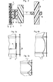
- the material constituting the external envelope 1 is an airtight composite material, having in the example three layers as shown in FIG. 3: on the outside a heat-sealable polyester film 4, on the inside a weldable polyethylene film 5 and, between the two, a "kevlar-polyester” fabric 6.
- the assembly has a thickness of the order of 200 microns.
- the fabric 6 comprises a polyester weft arranged in the circumferential direction and a "kevlar" warp arranged in the longitudinal direction. It thus has an asymmetric resistance, higher in the longitudinal direction than in the circumferential direction; moreover, it is inextensible in the longitudinal direction (by "inextensible” means a material whose elastic elongation does not exceed 1 to 2% approximately), whereas, in the circumferential direction, the material has a greater elasticity ( about 10% elongation).
- the outer envelope 1 is surrounded by a network of circumferential reinforcements such as 7 and a network of longitudinal reinforcements such as 8.
- the circumferential reinforcements 7 are located in planes perpendicular to the axis of the envelope, distributed over the height of the latter.
- Each circumferential reinforcement 7 consists of a strip of material inextensible of high resistance, for example "Kevlar" of 5/10 mm thick by 20 to 50 mm wide; the two ends of each strip are assembled by gluing one on the other.
- each strip 7 is linked at a few points to the external envelope 1, so as to be able to play relative to the latter in order to transmit to it only weak forces compared to those supported by said strip.
- the fastenings of each strip 7 are produced by means of conjugated portions 8 and 9 of attachment materials of the "Velcro" type, which are glued opposite, on the one hand, to the external envelope 1, on the other hand on the band concerned 7.
- Each reinforcing strip 7 is thus fixed around and outside of the external envelope 1 and, for the inflated state of this envelope, comes into contact with the latter over its entire periphery without transmitting significant constraints to it.
- the longitudinal reinforcements 8 are located in meridian planes distributed around the outer envelope; they are positioned outside the network of circumferential reinforcements, by positioning means which hold them.
- these positioning means are constituted by flexible belts 10 (fabric or other) which are crossed by said longitudinal reinforcements.
- Each reinforcement 8 is made of an inextensible material of high resistance and can be constituted as before by strips of "kevlar".
- the longitudinal reinforcements 8 extend integrally between the lower and upper poles of the outer casing and are fixed at these poles on the pole pieces 2 and 3.
- the outer casing 1 has a length in the longitudinal direction greater than the length of each longitudinal reinforcement strip 8, so that, in the fully inflated state, the longitudinal forces are essentially supported by the network of longitudinal reinforcements 8.
- the outer casing 1 in the not fully inflated state, has peripheral pleats P located between the circumferential reinforcements.
- lobes appear between the circumferential reinforcements, and are all the more pronounced the greater the pressure in the envelope (FIGS. 4b and 4c).
- pole pieces 2 and 3 are joined by an inextensible interpolar link 11 extending along the axis of the outer casing 1; in the example, this link is constituted by a bundle of bands made of an inextensible material of high resistance, in particular "kevlar".
- the length of the interpolar link 11 is less than that of the spindles forming the external envelope and is adjusted as a function of the various parameters of the balloon to obtain the desired external shape (cf. patent FR n ° 2 472 971 already mentioned).
- the balloon comprises an internal envelope 12 which is located inside the external envelope 1; this envelope 12 is produced in a manner analogous to the external envelope by assembling rectangular spindles whose upper and lower edges are joined together and fixed on the pole pieces 2 and 3.
- the internal envelope 12 thus has a cylindrical portion 12a and the diameter of the latter is dimensioned to correspond to that of the cylindrical portion ′ of the external envelope inflated to the maximum, so that this portion 12a comes to bear against the inflation against said portion 1a.
- the internal envelope has to withstand only low stresses and it can be made of a very thin material with a thickness less than that of the external envelope, in particular of the order of 50 microns; this material can be a composite material of the type comprising a layer of "mylar” coated with an aluminum coating in order to make it helium-tight.
- the inner shell is inflated with helium (or other gas lighter than air), while the outer shell is inflated with air.
- Helium inflation can only be carried out on the ground when the balloon is launched, the upper pole piece being provided with a safety valve to allow an escape in the event of an internal overpressure greater than a limit.
- the balloon can also be fitted with on-board means of inflating and deflating the internal envelope, in order to increase flight safety (leakage compensation, ability to increase the efficiency of piloting in the event of danger).
- the balloon is fitted with on-board means for admitting air into the external envelope and means for discharging air; these means are used on the ground for inflating said envelope and, in flight, for piloting it (an air intake causing a descent of the balloon and an air evacuation causing a rise).
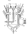
- FIG. 5 shows in axial section the lower pole piece 2 by means of which this air intake or exhaust takes place.
- This part forms an internal chamber 13 which communicates through lights 14 with the interior of the external envelope 1.
- the lower part of this external envelope is fixed in a sealed manner around said part below the lights. 14, however that the lower part of the internal envelope 12 is similarly fixed above said slots 14.
- Each envelope 1 or 12 is fixed around the part 2 by means of an annular bead 15 secured to the edge of the envelope and a clamp 16.
- the pole piece 2 externally comprises attachment means such as 17 of the bundle of bands forming the interpolar link 11 and attachment means such as 18 of the bands forming the network of longitudinal reinforcements 8; it also carries at its lower part a means 19 for hooking the load.
- the part 2 is equipped with a three-way valve 20, which allows either to carry out an air evacuation by an outlet 20a, or to admit compressed air coming from a turbo-compressor (or other equivalent means) through a duct 21.
- This turbo-compressor is on board and can be accommodated with the load.
- the internal envelope 12 is inflated with helium through a conduit 22 which passes tightly through the part 2 to open out in the upper part thereof through an orifice 22a located on the axis of the balloon.
- a porous sleeve 23 is provided inside thereof around the orifice 22a; this sleeve extends from one pole to the other: when the conduit 22 is connected to a high pressure helium source, this sleeve allows the gas entering the internal envelope to relax without risking damaging the latter .
- a valve closes the conduit 22 when it is disconnected from the helium source.
- FIGS 6a and 6b show the balloon described above in two different inflation states.
- the volume of its internal envelope which contains a constant amount of helium, croft, while that the mass of air of the external envelope decreases, the volume of the entire balloon remaining substantially constant.
- the structure of the balloon makes it possible to inflate its envelopes to considerably higher overpressures than those which conventional balloons can withstand.
- the stresses of tension of the internal envelope are taken up in a large proportion by the external envelope and by the interpolar link, while that the stresses of tension of the external envelope are taken up by the interpolar link, the longitudinal network 8 and the circumferential network 7.
- the asymmetry of resistance of the external envelope and its lobed structure when it is inflated contribute to increasing the limit value of the admissible overpressure; indeed, the expression of this limit value includes a term proportional to where t L is the longitudinal tension of the external envelope at its elastic limit, and r the radius of the lobes.
- the parameters of the balloon will be adjusted so as to optimize the stress field applied to the envelopes, so that the material of these works under the best conditions, that is to say, in each direction, to its elastic limit multiplied by a safety factor: the best compromise pressure / weight can 'be obtained.
- the structure described above makes it possible to obtain, at the level of the lobe concerned of the external envelope, an exceeding of the elastic limit intervening first in the circumferential sense, so that the possible rupture takes the form of a longitudinal slit limited by the two bands of circumferential reinforcements which border the lobe concerned. This avoids a sudden bursting of the balloon.
- the balloon is launched on the ground by inflating its outer envelope with air. During this inflation, the balloon remains extended on the ground, this position making it easier to control it than if it was erected vertically (during this phase, the balloon can, if necessary, be placed under cover in a hangar of running height, having an elongated shape).
- the balloon can be easily manipulated without contact with the fragile envelopes, by gripping it by the longitudinal 8 or circumferential bands 7.
- the internal envelope can have a volume of the order of a third or a quarter of the total volume of the balloon, while at the ceiling, it occupies almost the entire volume of the latter, the amount of air residual in the outer shell being small.
- the relative internal overpressure prevailing in the external envelope and in the internal envelope can be of the order of 500 millibars.
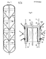
- Figures 7 and 8 are aimed at a variant similar to the previous one, but having several internal envelopes containing helium (the same references have been used in these figures as in the previous figures for similar bodies).
- the base of the lower internal envelope 12i is attached to a pole piece similar to the pole piece 2 previously described, while the upper part of the upper internal envelope 12s is attached to a pole piece similar to the pole piece 3.
- the other poles of said internal envelopes are fixed in intermediate positions on the interpolar link 11 by means of an intermediate pole piece 24, an exemplary embodiment of which is shown in FIG. 8.
- This cup-shaped piece overturned comprises hooking means 25 of the lower strands of the link 11, hooking means 26 of the upper strands of said link and fixing means 27 and 28 of the two internal envelopes concerned 12A and 12B; these latter means are similar to those of the pole piece already described.
- a network of longitudinal reinforcements such as 29 is preferably associated with each internal envelope and is hooked onto means 30 provided for this purpose on the piece 24.
- This additional network constituted by strips of " kevlar "analogous to those already described ensures a resumption of the longitudinal tensions which are applied on the internal envelopes, these longitudinal tensions being higher, in this embodiment, than in the previous one.
- helium conduit already described 22 is extended by a flexible conduit 31 disposed along the axis of the balloon and making it possible to inflate each inner envelope with helium independently by means of solenoid valves 32 provided at each of them. this.
- Such an embodiment conditions increased safety with regard to helium leaks, since the helium volume is divided into several separate volumes (the air leaks from the external envelope being less significant since they can be compensated by air intake).
- the internal envelopes can be constituted by separate envelopes as described above; they can also be produced by means of a single sheath of suitable height, which is clamped at the poles of the internal envelopes, by means of appropriate intermediate pole pieces.
- FIGS. 9 and 10 show the combination of five balloons B 1 , B 2 , B 3 9 B 4 and B 5 joined to each other. These balloons of different diameter make it possible to produce a set of desired horizontal profile. A net 33 retains these balloons and ensures the cohesion of the assembly; the interpolar links of each balloons are fixed on a trellis of beams symbolized at 34, which carries the load.
Landscapes
- Engineering & Computer Science (AREA)
- Mechanical Engineering (AREA)
- Aviation & Aerospace Engineering (AREA)
- Toys (AREA)
Applications Claiming Priority (2)
| Application Number | Priority Date | Filing Date | Title |
|---|---|---|---|
| FR8418798 | 1984-12-06 | ||
| FR8418798A FR2574369B1 (fr) | 1984-12-06 | 1984-12-06 | Ballon aerostatique pilotable |
Publications (2)
| Publication Number | Publication Date |
|---|---|
| EP0184262A1 true EP0184262A1 (de) | 1986-06-11 |
| EP0184262B1 EP0184262B1 (de) | 1988-04-27 |
Family
ID=9310399
Family Applications (1)
| Application Number | Title | Priority Date | Filing Date |
|---|---|---|---|
| EP85201975A Expired EP0184262B1 (de) | 1984-12-06 | 1985-11-26 | Steuerbarer aerostatischer Ballon |
Country Status (8)
| Country | Link |
|---|---|
| US (1) | US4711416A (de) |
| EP (1) | EP0184262B1 (de) |
| JP (1) | JPS62501407A (de) |
| BR (1) | BR8507096A (de) |
| CA (1) | CA1255644A (de) |
| DE (1) | DE3562354D1 (de) |
| FR (1) | FR2574369B1 (de) |
| WO (1) | WO1986003469A1 (de) |
Cited By (6)
| Publication number | Priority date | Publication date | Assignee | Title |
|---|---|---|---|---|
| FR2659933A1 (fr) * | 1990-03-20 | 1991-09-27 | R P Dev Sarl | Systeme de reprise de contraintes longitudinales a l'extremite d'une structure souple, et son procede de fabrication. |
| EP0321012B1 (de) * | 1987-12-02 | 1992-04-15 | CENTRE NATIONAL D'ETUDES SPATIALES (C.N.E.S.) Etablissement public, scientifique et | Luftballon, bestimmt zur selbstständigen und umsteuerbaren Bewegung zwischen dem Boden eines Planeten mit einer Atmosphäre und einer vorherbestimmten Höhe |
| WO1996015939A1 (en) * | 1994-11-21 | 1996-05-30 | Franco Carloni | Air balloon containing inert gas |
| FR2867450A1 (fr) * | 2004-03-09 | 2005-09-16 | Francois Nicolas Jean Villon | Ballon a ascension controlable |
| CN105546332A (zh) * | 2015-09-21 | 2016-05-04 | 王明华 | 一种氦气和空气混合充装气球的方法和装置 |
| CN108100211A (zh) * | 2016-11-25 | 2018-06-01 | 海口未来技术研究院 | 浮空器 |
Families Citing this family (39)
| Publication number | Priority date | Publication date | Assignee | Title |
|---|---|---|---|---|
| US4850551A (en) * | 1987-12-14 | 1989-07-25 | Lockheed Corporation | Propulsion system for a buoyant vehicle |
| DE4023112C2 (de) * | 1990-07-20 | 1994-06-09 | Gehse Hartmut | Aerostatischer offener oder geschlossener Freiballon, insbesondere für den Einsatz in grossen Höhen |
| FR2681306A1 (fr) * | 1991-09-16 | 1993-03-19 | Bigotte Claude | Procede de sustentation des aerostats en autonomie de lestage. |
| US5297763A (en) * | 1993-03-01 | 1994-03-29 | Cazort Brad A | Safety balloon apparatus |
| US20030236070A1 (en) | 2002-06-25 | 2003-12-25 | Seligsohn Sherwin I. | Sub-orbital, high altitude communications system |
| KR100442209B1 (ko) * | 1993-07-30 | 2004-11-06 | 인터내셔널 멀티미디어 코포레이션 | 서브오비탈고공통신시스템 |
| US5743786A (en) * | 1996-05-30 | 1998-04-28 | Lindsey; Alan | Balloon face polyhedra |
| US5810286A (en) * | 1996-10-11 | 1998-09-22 | Matsler; Winfield R. | Lighter-than-air aircraft |
| US6016991A (en) * | 1997-01-24 | 2000-01-25 | Lowe, Jr.; Charles S. | Evacuated rotating envelope aircraft |
| US6270036B1 (en) | 1997-01-24 | 2001-08-07 | Charles S. Lowe, Jr. | Blown air lift generating rotating airfoil aircraft |
| US6427943B2 (en) * | 1998-10-07 | 2002-08-06 | Fuji Jukogyo Kabushiki Kaisha | Stratospheric airship |
| FR2790441B1 (fr) | 1999-03-02 | 2001-06-01 | Regipa And Partners Dev | Ensemble aerostatique comprenant une pluralite de ballons pressurises |
| FR2790440B1 (fr) | 1999-03-02 | 2001-06-01 | Regipa And Partners Dev | Dispositif et procede d'ancrage d'une nappe de materiau souple a un element d'amarrage |
| AU2000272999A1 (en) | 2000-09-07 | 2002-03-22 | Interactive Star | Device and method for hooking a band of flexible material to a securing device |
| WO2002028707A1 (fr) | 2000-10-03 | 2002-04-11 | Regipa And Partners Development | Ensemble aerostatique comprenant une pluralite de ballons pressurises |
| CN1331710C (zh) * | 2000-12-22 | 2007-08-15 | 张涛 | 一种硬壳飞艇及其升降方法以及该飞艇壳体的制造方法 |
| JP2003175895A (ja) * | 2001-12-13 | 2003-06-24 | Inst Of Space & Astronautical Science | 膜構造体 |
| WO2003064253A1 (de) * | 2002-01-30 | 2003-08-07 | Konrad Walter | Fluggerät |
| FR2877315B1 (fr) * | 2004-10-29 | 2007-02-02 | Eads Space Transp Sas Soc Par | Dispositif de commande du deploiement de structures gonflables |
| US8704397B2 (en) * | 2005-06-09 | 2014-04-22 | Yehuda Roseman | System for producing electricity from jetstreams and tower therefor |
| US7552893B2 (en) * | 2005-09-28 | 2009-06-30 | 21St Century Airship Technologies Inc. | Airship & method of operation |
| US8091826B2 (en) * | 2007-04-24 | 2012-01-10 | Michael Todd Voorhees | Aerostatic buoyancy control system |
| JP5528687B2 (ja) * | 2008-07-15 | 2014-06-25 | 独立行政法人 宇宙航空研究開発機構 | 耐圧大型膜構造物 |
| US20140061370A1 (en) * | 2011-02-17 | 2014-03-06 | George L. Vojtech | Airship and a Method for Controlling the Airship |
| WO2012118731A2 (en) * | 2011-03-01 | 2012-09-07 | Ciampa John A | Lighter-than-air systems, methods, and kits for obtaining aerial images |
| US8505847B2 (en) | 2011-03-01 | 2013-08-13 | John Ciampa | Lighter-than-air systems, methods, and kits for obtaining aerial images |
| US9694910B2 (en) | 2013-02-22 | 2017-07-04 | World View Enterprises Inc. | Near-space operation systems |
| US20160083068A1 (en) * | 2013-11-17 | 2016-03-24 | Austyn D. Crites | High Altitude Balloon |
| US9580161B1 (en) * | 2013-12-20 | 2017-02-28 | X Development Llc | Reinforcing ripstop tape for burst mitigation |
| US9463863B1 (en) | 2013-12-30 | 2016-10-11 | Google Inc. | Superpressure balloon with ballonet cut from contiguous gores |
| US9573671B1 (en) * | 2013-12-31 | 2017-02-21 | X Development Llc | Fabric diffuser for high flowrate inflation |
| US9327817B1 (en) * | 2014-02-03 | 2016-05-03 | Google Inc. | Ballonet for a balloon |
| US9327818B1 (en) * | 2014-02-05 | 2016-05-03 | Google Inc. | Ballonet for a balloon |
| US10787268B2 (en) | 2015-03-09 | 2020-09-29 | World View Enterprises Inc. | Rigidized assisted opening system for high altitude parafoils |
| US9540091B1 (en) | 2016-02-11 | 2017-01-10 | World View Enterprises Inc. | High altitude balloon systems and methods |
| US20180093750A1 (en) * | 2016-10-05 | 2018-04-05 | The Boeing Company | Puffing propulsion for super pressure balloons |
| US10336432B1 (en) | 2017-01-09 | 2019-07-02 | World View Enterprises Inc. | Lighter than air balloon systems and methods |
| US10124875B1 (en) | 2017-01-09 | 2018-11-13 | World View Enterprises Inc. | Continuous multi-chamber super pressure balloon |
| US11577813B2 (en) * | 2020-12-14 | 2023-02-14 | Aerostar International, Llc | Outer membrane for aerial vehicles |
Citations (3)
| Publication number | Priority date | Publication date | Assignee | Title |
|---|---|---|---|---|
| DE239989C (de) * | ||||
| US3432122A (en) * | 1967-06-19 | 1969-03-11 | Goodyear Aerospace Corp | Combination ballonet and dilation system for balloons |
| GB2026971A (en) * | 1978-08-04 | 1980-02-13 | Solar Srl | An aerostatic balloon of air type heated by solar energy |
Family Cites Families (13)
| Publication number | Priority date | Publication date | Assignee | Title |
|---|---|---|---|---|
| US2038671A (en) * | 1930-12-06 | 1936-04-28 | Olan Mary Ellen | Airship |
| DE696253C (de) * | 1938-06-08 | 1940-09-16 | Luftschiffbau Zeppelin G M B H | Fesselballon |
| US2492800A (en) * | 1948-08-16 | 1949-12-27 | Dewey And Almy Chem Comp | Fast rising sounding balloon |
| US3180590A (en) * | 1963-01-23 | 1965-04-27 | Aereon Corp | Pressurized airship |
| US3391883A (en) * | 1965-04-19 | 1968-07-09 | Schjeldahl Co G T | Gore tailoring |
| US3871603A (en) * | 1974-05-30 | 1975-03-18 | Schjeldahl Co G T | Fin attachment for tethered balloon structures |
| US3971533A (en) * | 1975-02-25 | 1976-07-27 | Slater Saul I | Convertible airship |
| US4032086A (en) * | 1975-10-20 | 1977-06-28 | William Douglas Cooke | Aerostats and aquastats |
| US4090682A (en) * | 1976-03-25 | 1978-05-23 | Raven Industries, Inc. | Pressure and hot air relief vents for a pressurized hot air airship |
| US4033527A (en) * | 1976-02-03 | 1977-07-05 | Raven Industries, Inc. | Deflation cap for pressurized hot air airship |
| FR2464898A1 (fr) * | 1979-09-06 | 1981-03-20 | Centre Nat Etd Spatiales | Procede de realisation d'un conteneur a structure symetrique lobee et conteneur realise selon ledit procede |
| FR2472971A1 (fr) * | 1980-01-04 | 1981-07-10 | Centre Nat Etd Spatiales | Procede de realisation d'une enveloppe en particulier pour ballons spatiaux, enveloppe realisee, et utilisation de celle-ci dans le domaine aerospatial |
| JPH0233559B2 (ja) * | 1982-08-19 | 1990-07-27 | Fujita Corp | Gasukikyu |
-
1984
- 1984-12-06 FR FR8418798A patent/FR2574369B1/fr not_active Expired
-
1985
- 1985-11-25 WO PCT/FR1985/000332 patent/WO1986003469A1/fr not_active Ceased
- 1985-11-25 JP JP60505297A patent/JPS62501407A/ja active Pending
- 1985-11-25 BR BR8507096A patent/BR8507096A/pt not_active IP Right Cessation
- 1985-11-26 EP EP85201975A patent/EP0184262B1/de not_active Expired
- 1985-11-26 DE DE8585201975T patent/DE3562354D1/de not_active Expired
- 1985-12-05 US US06/804,887 patent/US4711416A/en not_active Expired - Lifetime
- 1985-12-05 CA CA000496921A patent/CA1255644A/fr not_active Expired
Patent Citations (3)
| Publication number | Priority date | Publication date | Assignee | Title |
|---|---|---|---|---|
| DE239989C (de) * | ||||
| US3432122A (en) * | 1967-06-19 | 1969-03-11 | Goodyear Aerospace Corp | Combination ballonet and dilation system for balloons |
| GB2026971A (en) * | 1978-08-04 | 1980-02-13 | Solar Srl | An aerostatic balloon of air type heated by solar energy |
Cited By (8)
| Publication number | Priority date | Publication date | Assignee | Title |
|---|---|---|---|---|
| EP0321012B1 (de) * | 1987-12-02 | 1992-04-15 | CENTRE NATIONAL D'ETUDES SPATIALES (C.N.E.S.) Etablissement public, scientifique et | Luftballon, bestimmt zur selbstständigen und umsteuerbaren Bewegung zwischen dem Boden eines Planeten mit einer Atmosphäre und einer vorherbestimmten Höhe |
| FR2659933A1 (fr) * | 1990-03-20 | 1991-09-27 | R P Dev Sarl | Systeme de reprise de contraintes longitudinales a l'extremite d'une structure souple, et son procede de fabrication. |
| WO1996015939A1 (en) * | 1994-11-21 | 1996-05-30 | Franco Carloni | Air balloon containing inert gas |
| US5931412A (en) * | 1994-11-21 | 1999-08-03 | Carloni; Franco | Air balloon containing inert gas |
| FR2867450A1 (fr) * | 2004-03-09 | 2005-09-16 | Francois Nicolas Jean Villon | Ballon a ascension controlable |
| CN105546332A (zh) * | 2015-09-21 | 2016-05-04 | 王明华 | 一种氦气和空气混合充装气球的方法和装置 |
| CN108100211A (zh) * | 2016-11-25 | 2018-06-01 | 海口未来技术研究院 | 浮空器 |
| CN108100211B (zh) * | 2016-11-25 | 2024-04-26 | 佛山顺德光启尖端装备有限公司 | 浮空器 |
Also Published As
| Publication number | Publication date |
|---|---|
| WO1986003469A1 (fr) | 1986-06-19 |
| FR2574369A1 (fr) | 1986-06-13 |
| JPS62501407A (ja) | 1987-06-11 |
| US4711416A (en) | 1987-12-08 |
| EP0184262B1 (de) | 1988-04-27 |
| BR8507096A (pt) | 1987-03-31 |
| FR2574369B1 (fr) | 1987-01-09 |
| DE3562354D1 (en) | 1988-06-01 |
| CA1255644A (fr) | 1989-06-13 |
Similar Documents
| Publication | Publication Date | Title |
|---|---|---|
| EP0184262B1 (de) | Steuerbarer aerostatischer Ballon | |
| EP2440446B1 (de) | Aufblasbare evakuierungsrampe und rettungsausrüstung für schiffe damit | |
| EP0031981B1 (de) | Verfahren zur Herstellung einer Raumballonhülle, hergestellte Hülle und deren Verwendung in der Raumfahrt | |
| EP0956236B1 (de) | Vorrichtung zum aufhängen einer nutzlast in einer trägerrakete | |
| FR2675462A1 (fr) | Dirigeable dont l'enveloppe entourant les chambres a air est montee sur un chassis porteur forme d'une serie de couples transversaux et de poutres longitudinales. | |
| EP3475164B1 (de) | Segelantriebselement mit einem aufblasbaren segel mit einem symmetrischen profil | |
| EP0895504A1 (de) | Stratospharenballon mit langer flugzeit | |
| EP0132175A1 (de) | Lagerbehälter für Flüssigkeiten mittels kapillarer Aufbewahrung | |
| EP3187410B1 (de) | Hybridluftschiff mit flexibler und unterteilter aussenhülle | |
| EP0401891B1 (de) | Luftballon, bestimmt zur selbständigen und umsteuerbaren Bewegung zwischen dem Boden eines Planeten mit einer Atmosphäre und einer vorherbestimmten Höhe | |
| EP2864194B1 (de) | Stratosphärenballon mit verbesserter druckfestigkeit | |
| EP0033020B1 (de) | Verfahren und Vorrichtung zum Starten und Aufblasen eines Raumfahrballons | |
| FR2581022A1 (fr) | Dispositif pour l'accouplement d'une enveloppe avec un element externe a l'enveloppe | |
| EP0241970B1 (de) | Verfahren und Einrichtung zur Entfaltung einer Hülle um ein Objekt, insbesondere um einen Satelliten | |
| EP0321012B1 (de) | Luftballon, bestimmt zur selbstständigen und umsteuerbaren Bewegung zwischen dem Boden eines Planeten mit einer Atmosphäre und einer vorherbestimmten Höhe | |
| FR2669602A1 (fr) | Aerostat comprenant au moins un ballon cylindrique a geometrie variable. | |
| EP2855260B1 (de) | Zeppelin | |
| WO1993006004A1 (fr) | Procede de sustentation des aerostats en autonomie de lestage | |
| FR2797847A1 (fr) | Aile de traction nautique | |
| FR2628061A1 (fr) | Dispositif perfectionne de suspension de la nacelle pour ballon dirigeable souple | |
| FR2844478A1 (fr) | Enveloppe de roue de vehicule | |
| FR2851224A1 (fr) | Aeronefs hybrides, comportant un systeme d'allegement torique et une voilure tournante centrale | |
| WO2022008365A1 (fr) | Aéronef sans pilote télécommandé comprenant une structure gonflable | |
| EP3882044A1 (de) | Radfelge für ein fahrrad mit luftablassvorrichtung, rad und radanordnung mit einer solchen felge | |
| FR3130686A1 (fr) | Matériau laminé pour une enveloppe gonflable d’un aérostat stratosphérique |
Legal Events
| Date | Code | Title | Description |
|---|---|---|---|
| PUAI | Public reference made under article 153(3) epc to a published international application that has entered the european phase |
Free format text: ORIGINAL CODE: 0009012 |
|
| AK | Designated contracting states |
Kind code of ref document: A1 Designated state(s): BE CH DE FR GB IT LI LU NL |
|
| 17P | Request for examination filed |
Effective date: 19860723 |
|
| 17Q | First examination report despatched |
Effective date: 19870818 |
|
| GRAA | (expected) grant |
Free format text: ORIGINAL CODE: 0009210 |
|
| AK | Designated contracting states |
Kind code of ref document: B1 Designated state(s): BE CH DE FR GB IT LI LU NL |
|
| REF | Corresponds to: |
Ref document number: 3562354 Country of ref document: DE Date of ref document: 19880601 |
|
| ITF | It: translation for a ep patent filed | ||
| GBT | Gb: translation of ep patent filed (gb section 77(6)(a)/1977) | ||
| PLBE | No opposition filed within time limit |
Free format text: ORIGINAL CODE: 0009261 |
|
| STAA | Information on the status of an ep patent application or granted ep patent |
Free format text: STATUS: NO OPPOSITION FILED WITHIN TIME LIMIT |
|
| 26N | No opposition filed | ||
| EPTA | Lu: last paid annual fee | ||
| REG | Reference to a national code |
Ref country code: FR Ref legal event code: TP |
|
| PGFP | Annual fee paid to national office [announced via postgrant information from national office to epo] |
Ref country code: CH Payment date: 19981110 Year of fee payment: 14 |
|
| PGFP | Annual fee paid to national office [announced via postgrant information from national office to epo] |
Ref country code: GB Payment date: 19981119 Year of fee payment: 14 |
|
| PGFP | Annual fee paid to national office [announced via postgrant information from national office to epo] |
Ref country code: NL Payment date: 19981130 Year of fee payment: 14 |
|
| PGFP | Annual fee paid to national office [announced via postgrant information from national office to epo] |
Ref country code: LU Payment date: 19981210 Year of fee payment: 14 |
|
| PGFP | Annual fee paid to national office [announced via postgrant information from national office to epo] |
Ref country code: BE Payment date: 19981215 Year of fee payment: 14 |
|
| PG25 | Lapsed in a contracting state [announced via postgrant information from national office to epo] |
Ref country code: LU Free format text: LAPSE BECAUSE OF NON-PAYMENT OF DUE FEES Effective date: 19991126 Ref country code: GB Free format text: LAPSE BECAUSE OF NON-PAYMENT OF DUE FEES Effective date: 19991126 |
|
| PG25 | Lapsed in a contracting state [announced via postgrant information from national office to epo] |
Ref country code: LI Free format text: LAPSE BECAUSE OF NON-PAYMENT OF DUE FEES Effective date: 19991130 Ref country code: CH Free format text: LAPSE BECAUSE OF NON-PAYMENT OF DUE FEES Effective date: 19991130 Ref country code: BE Free format text: LAPSE BECAUSE OF NON-PAYMENT OF DUE FEES Effective date: 19991130 |
|
| BERE | Be: lapsed |
Owner name: CENTRE NATIONAL D'ETUDES SPATIALES ETABLISSEMENT Effective date: 19991130 |
|
| PG25 | Lapsed in a contracting state [announced via postgrant information from national office to epo] |
Ref country code: NL Free format text: LAPSE BECAUSE OF NON-PAYMENT OF DUE FEES Effective date: 20000601 |
|
| REG | Reference to a national code |
Ref country code: CH Ref legal event code: PL |
|
| GBPC | Gb: european patent ceased through non-payment of renewal fee |
Effective date: 19991126 |
|
| NLV4 | Nl: lapsed or anulled due to non-payment of the annual fee |
Effective date: 20000601 |
|
| PGFP | Annual fee paid to national office [announced via postgrant information from national office to epo] |
Ref country code: DE Payment date: 20021218 Year of fee payment: 18 |
|
| PG25 | Lapsed in a contracting state [announced via postgrant information from national office to epo] |
Ref country code: DE Free format text: LAPSE BECAUSE OF NON-PAYMENT OF DUE FEES Effective date: 20040602 |
|
| PGFP | Annual fee paid to national office [announced via postgrant information from national office to epo] |
Ref country code: FR Payment date: 20041124 Year of fee payment: 20 |