EP0184271A2 - Verfahren zur Mengendurchflussregelung von Verdichterdiffusoren - Google Patents
Verfahren zur Mengendurchflussregelung von Verdichterdiffusoren Download PDFInfo
- Publication number
- EP0184271A2 EP0184271A2 EP85202095A EP85202095A EP0184271A2 EP 0184271 A2 EP0184271 A2 EP 0184271A2 EP 85202095 A EP85202095 A EP 85202095A EP 85202095 A EP85202095 A EP 85202095A EP 0184271 A2 EP0184271 A2 EP 0184271A2
- Authority
- EP
- European Patent Office
- Prior art keywords
- diffuser
- entrance
- compressor
- area
- stage
- Prior art date
- Legal status (The legal status is an assumption and is not a legal conclusion. Google has not performed a legal analysis and makes no representation as to the accuracy of the status listed.)
- Withdrawn
Links
- 238000000034 method Methods 0.000 title claims description 10
- 230000007704 transition Effects 0.000 abstract description 14
- 239000002131 composite material Substances 0.000 abstract 1
- 239000007789 gas Substances 0.000 description 35
- 238000000926 separation method Methods 0.000 description 4
- 230000008901 benefit Effects 0.000 description 3
- 230000008859 change Effects 0.000 description 3
- 238000006243 chemical reaction Methods 0.000 description 3
- 238000009792 diffusion process Methods 0.000 description 3
- 238000011084 recovery Methods 0.000 description 3
- 238000002485 combustion reaction Methods 0.000 description 2
- 230000007423 decrease Effects 0.000 description 2
- 239000000446 fuel Substances 0.000 description 2
- 230000007246 mechanism Effects 0.000 description 2
- 230000009467 reduction Effects 0.000 description 2
- 230000002411 adverse Effects 0.000 description 1
- 239000000567 combustion gas Substances 0.000 description 1
- 230000003247 decreasing effect Effects 0.000 description 1
- 230000001419 dependent effect Effects 0.000 description 1
- 230000000694 effects Effects 0.000 description 1
- 238000012423 maintenance Methods 0.000 description 1
- 238000004519 manufacturing process Methods 0.000 description 1
- 238000007789 sealing Methods 0.000 description 1
- 125000006850 spacer group Chemical group 0.000 description 1
- 230000003068 static effect Effects 0.000 description 1
Images
Classifications
-
- F—MECHANICAL ENGINEERING; LIGHTING; HEATING; WEAPONS; BLASTING
- F01—MACHINES OR ENGINES IN GENERAL; ENGINE PLANTS IN GENERAL; STEAM ENGINES
- F01D—NON-POSITIVE DISPLACEMENT MACHINES OR ENGINES, e.g. STEAM TURBINES
- F01D17/00—Regulating or controlling by varying flow
- F01D17/10—Final actuators
- F01D17/12—Final actuators arranged in stator parts
- F01D17/14—Final actuators arranged in stator parts varying effective cross-sectional area of nozzles or guide conduits
- F01D17/141—Final actuators arranged in stator parts varying effective cross-sectional area of nozzles or guide conduits by means of shiftable members or valves obturating part of the flow path
-
- F—MECHANICAL ENGINEERING; LIGHTING; HEATING; WEAPONS; BLASTING
- F04—POSITIVE - DISPLACEMENT MACHINES FOR LIQUIDS; PUMPS FOR LIQUIDS OR ELASTIC FLUIDS
- F04D—NON-POSITIVE-DISPLACEMENT PUMPS
- F04D29/00—Details, component parts, or accessories
- F04D29/40—Casings; Connections of working fluid
- F04D29/52—Casings; Connections of working fluid for axial pumps
- F04D29/54—Fluid-guiding means, e.g. diffusers
- F04D29/56—Fluid-guiding means, e.g. diffusers adjustable
Definitions
- This invention relates to a method for controlling the mass flow rate through a rotary compressor having at least one closely coupled pipe diffuser having a smoothly varying cross-sectional area in the flow direction and also an entrance positioned to receive relatively high velocity gas from the compressor, and an exit to deliver relatively low velocity, high pressure gas.
- Pipe-type compressor diffusers have an advantage over vane-type diffusers in that they can provide a better structural member for the compressor and related components in certain applications, such as gas turbine engines. Furthermore, as a result of the discrete spacing of such pipe-type diffusers about the axis of a rotary compressor, such diffusers allow for interchannel spacings where various conduits for gas and oil can be passed for use elsewhere in the system.
- the present invention relates to a method where a pipe-type diffuser is utilized but where further diffusion recovers a significant part of the otherwise lost kinetic energy.
- the present invention also provides a method for controllably varying the overall gas turbine engine mass flow rate, another feature important to the maintenance of high thermal efficiency at part load in recuperated gas turbine engines.
- the method for controlling the mass flow rate through a rotary compressor is characterised by the step of smoothly varying the cross-sectional flow area of the diffuser entrance to obtain a desired compressor mass flow rate, the entrance area varying step including the substeps of positioning an aerodynamically shaped body having an axially varying cross-sectional area in the conical diffuser portion of the diffuser near the entrance, and adjusting the axial position of the body relative to the entrance to provide the desired effective entrance cross-sectional flow area.
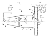
- Fig 1 is a schematic view of a diffuser apparatus for use in carrying out a method embodying the present invention and shown in use in a gas turbine engine application.
- Gas turbine engine apparatus 18 includes a rotary compressor 10 having an inlet ducting 12 and having an outlet operatively connected to a pipe or channel diffuser apapratus 16.
- Compressor 10 can be axial or radial or mixed axial- radial and the present example is not intended to limit the type of rotary compressor with which the present invention can be used.
- diffuser 16 is shown schematically separate from compressor 10 for easy understanding, one of ordinary skill in the art would understand that diffuser 16 can be made part of the compressor 10 housing, and this may be preferred because the diffuser 16 can be integrated into the framework of the compressor housing and add strength and rigidity to the overall structure.
- the function of diffuser 16 is to convert the kinetic energy of the high velocity gas exiting the compressor 10 to a relatively higher static pressure, low velocity gas to be utilized, for instance by the other components of the gas turbine engine apparatus 18 to be discussed henceforth.
- the high pressure, low velocity gas flows from diffuser 16 via ducting 20 to a combustion chamber 22 where it is mixed with fuel from a fuel source 24 and combusted.
- the hot combustion gases are then fed to turbine 26 via ducting 28 and expanded to produce mechanical work, as is well known.
- heat values can be recovered from the turbine exhaust 30 and transferred to the compressed gas in ducting 20 by apparatus such as a regenerator 32 (shown in broken lines in Fig 1).
- apparatus such as a regenerator 32 (shown in broken lines in Fig 1).
- regenerator 32 shown in broken lines in Fig 1).
- the diffuser 16 includes a first stage having a smoothly increasing cross-sectional flow area operatively connected to compressor 10 by ducting 14 to receive the high velocity gas from compressor 10.
- diffuser 16 has a conical housing 34 which is symmetric about axis 36 and has a circular entrance 38 adapted to receive gas from compressor 10 via ducting 14.
- Other, non-circular cross-sections such as rectangular, elliptical, etc shapes may, of course be used in place of the conical shape and are considered within the scope of the present invention.
- ducting 14 will be configured such that entrance 38 is proximate the vane tips (not shown) of compressor 10 such that diffuser 16 is closely coupled aerodynamically to compressor 10.
- the present invention contemplates conical housing 34 continuously increasing in cross-sectional area from the entrance 38 to the end 40 of the conical section.
- the diameter at the end 40 is about 2 to 4 times the diameter of entrance 38.
- a transition diffuser stage at the outlet of the first stage removes spatial variations in the gas velocity profile introduced in the conical section. It is known to those skilled in the art that flow through a conical diffuser results in a velocity profile highly skewed toward the center, with low velocities toward the conical wall. This is depicted schematically by the profile 42 in Fig 1. Under certain, unwanted circumstances, the velocities near the conical wall can approach zero and become negative, indicating incipient reverse flow in the boundary layer next to the wall, possibly leading to boundary layer lift-off and separation. In order to control the boundary layer and to most effectively utilize the final plate-type diffuser stage 50 (to be discussed hereinafter), the transition stage should make the velocity profile nearly uniform across the flow cross section.
- the transition diffuser stage includes a straight pipe portion 44 having essentially constant cross-sectional flow area between the conical stage outlet 40 and the end 46 of the transition stage.
- Pipe member 44 is aligned with its axis of symmetry co-linear with the conical stage axis 36.
- Pipe member 44 should be of sufficient length to allow mixing of the high velocity core (center flow) and the low velocity wall flows such that a relatively flat profile emerges at the transition stage end 46 (depicted schematically by profile 48).
- a pipe member 44 length of about 2.5 to 4.5 times the pipe 44 diameter should be used, and the diameter of pipe 44 should be equal to the diameter of end 40 of the conical stage to provide a smooth transition from the conical stage to the transition stage.
- transition diffuser stage will result in recovery of 50-60% of the theoretically recoverable kinetic energy remaining after the conical diffuser stage.
- the available kinetic energy represents 2-3 compressor efficiency percentage points.
- a plate-type diffuser stage is provided to further diffuse the gas leaving the transition diffuser stage.
- the plate diffuser stage includes an annular flange 50, an axial inlet 52 and, together with impact wall 56, forms an annular radial exit 54.
- Wall 56 serves to turn the impinging gas flow from a predominantly axial flow direction at the transition stage oulet 46 to a predominantly radial flow through the plate diffuser stage exit 54.
- gas flow leaving the plate diffuser stage exit 54 is collected and channelled to the combustion chamber 22 by ducting 20, as was explained previously.
- the ratio of the cross-sectional flow area at the plate diffuser stage exit 54 to the flow area at the plate diffuser inlet 52 will range from about 2.5:1 to 3.5:1, and an overall exit/entrance area ratio for diffuser 16 (that is, plate diffuser stage exit 54 area/conical diffuser stage entrance 38 area) from about 8.5:1 to 15:1 should be achieveable, depending upon available space and the stability of compressor 10.
- means are provided for adjustably varying the overall exit/entrance area ratio of the diffuser to provide control for the gas mass flow rate through the compressor and through the remainder of the gas turbine engine.
- the diffuser is the mass flow controlling element for high pressure ratio rotary compressors using closely coupled diffusers.
- the entrance (throat) region is normally choked and therefore a variation in throat area will provide an equal variation in mass flow, as is well understood from gas dynamics considerations.
- the variation in mass flow also is dependent upon the absolute throat velocity, but the effect of the area variation is predominant as one skilled in the art would understand and appreciate.
- the method for compressor mass flow rate control utilizes means for smoothly varying the cross-sectional area available for gas flow in the conical diffuser stage 34, while maintaining the cross-sectional flow area in the transition diffuser stage 44 and the plate diffuser stage 50, including exit 54, essentially constant.
- the area ratio varying means includes a spike member 60 positioned for movement along axis 36 in the portion of conical stage 34 near the entrance 38. Spike member 60 is connected to rod member 62 which extends the length of diffuser 16 and penetrates the plate diffuser stage wall 56 through aperture 58.
- a suitable sealing and bearing assembly 64 is provided at aperture 58 to allow reciprocal axial movement of rod 62 without leakage of the compressed gas, at least in part, and thus wall 56 acts to support rod 62 and spike 60. Additional bearing support for rod 62 may be provided, such as collar 66 and spacer strut 68 shown in Fig 1 (only two of three evenly spaced struts shown).
- Spike 60 includes an aerodynamically contoured face portion 70 for presentation to the high velocity gases received from compressor 10. Also, the rear portion (unnumbered) of spike 60 should be smoothly tapered where it is fixedly connected to rod 62 to preclude abrupt expansion and consequent flow separation losses in that area.
- Fig 1 Also included in the area ratio varying means depicted in Fig 1 are means for adjusting the axial position of spike 60, including pivoting assembly 72 shown operatively connected to rod 62 outside plate diffuser stage wall 56. Although a lever mechanism is shown, it is clear that other actuating mechanisms of the mechanical, hydraulic, pneumatic and electrical types can be utilized to adjustably position rod 62 and spike 60.
Landscapes
- Engineering & Computer Science (AREA)
- Mechanical Engineering (AREA)
- General Engineering & Computer Science (AREA)
- Structures Of Non-Positive Displacement Pumps (AREA)
Applications Claiming Priority (2)
| Application Number | Priority Date | Filing Date | Title |
|---|---|---|---|
| US06/438,990 US4549847A (en) | 1982-11-04 | 1982-11-04 | High area ratio, variable entrance geometry compressor diffuser |
| US438990 | 1982-11-04 |
Related Parent Applications (2)
| Application Number | Title | Priority Date | Filing Date |
|---|---|---|---|
| EP83306164.1 Division | 1983-10-12 | ||
| EP83306164A Division EP0108523B1 (de) | 1982-11-04 | 1983-10-12 | Kompressordiffusor |
Publications (2)
| Publication Number | Publication Date |
|---|---|
| EP0184271A2 true EP0184271A2 (de) | 1986-06-11 |
| EP0184271A3 EP0184271A3 (de) | 1986-09-17 |
Family
ID=23742840
Family Applications (2)
| Application Number | Title | Priority Date | Filing Date |
|---|---|---|---|
| EP83306164A Expired EP0108523B1 (de) | 1982-11-04 | 1983-10-12 | Kompressordiffusor |
| EP85202095A Withdrawn EP0184271A3 (de) | 1982-11-04 | 1983-10-12 | Verfahren zur Mengendurchflussregelung von Verdichterdiffusoren |
Family Applications Before (1)
| Application Number | Title | Priority Date | Filing Date |
|---|---|---|---|
| EP83306164A Expired EP0108523B1 (de) | 1982-11-04 | 1983-10-12 | Kompressordiffusor |
Country Status (4)
| Country | Link |
|---|---|
| US (1) | US4549847A (de) |
| EP (2) | EP0108523B1 (de) |
| JP (1) | JPS5999099A (de) |
| DE (1) | DE3373327D1 (de) |
Families Citing this family (12)
| Publication number | Priority date | Publication date | Assignee | Title |
|---|---|---|---|---|
| US5077967A (en) * | 1990-11-09 | 1992-01-07 | General Electric Company | Profile matched diffuser |
| US5207559A (en) * | 1991-07-25 | 1993-05-04 | Allied-Signal Inc. | Variable geometry diffuser assembly |
| RU2171403C1 (ru) * | 1999-12-21 | 2001-07-27 | Открытое акционерное общество "Авиадвигатель" | Компрессор газотурбинного двигателя |
| RU2188969C2 (ru) * | 2000-05-26 | 2002-09-10 | Открытое акционерное общество "Авиадвигатель" | Статор газотурбинного двигателя |
| JP2002172438A (ja) * | 2000-12-06 | 2002-06-18 | Futaba Corp | 金型装置 |
| RU2193699C2 (ru) * | 2001-02-05 | 2002-11-27 | Открытое акционерное общество "Авиадвигатель" | Статор компрессора газотурбинного двигателя |
| GB2390890B (en) * | 2002-07-17 | 2005-07-06 | Rolls Royce Plc | Diffuser for gas turbine engine |
| US7101151B2 (en) * | 2003-09-24 | 2006-09-05 | General Electric Company | Diffuser for centrifugal compressor |
| US7905703B2 (en) * | 2007-05-17 | 2011-03-15 | General Electric Company | Centrifugal compressor return passages using splitter vanes |
| US9651138B2 (en) | 2011-09-30 | 2017-05-16 | Mtd Products Inc. | Speed control assembly for a self-propelled walk-behind lawn mower |
| CN105736076B (zh) * | 2016-02-01 | 2017-07-28 | 西安交通大学 | 一种利用汽轮机排汽余速损失的导流器 |
| CN117345353B (zh) * | 2023-12-04 | 2024-01-26 | 西北工业大学 | 一种具有变长度摇臂的可调静子结构及压气机 |
Family Cites Families (15)
| Publication number | Priority date | Publication date | Assignee | Title |
|---|---|---|---|---|
| US3123285A (en) * | 1964-03-03 | Diffuser with boundary layer control | ||
| AT77080B (de) * | 1916-08-02 | 1919-07-10 | Victor Ing Dr Kaplan | Düse zur Umsetzung von Geschwindigkeit in Druck. |
| US1449873A (en) * | 1922-01-20 | 1923-03-27 | Frederick W Steuber | Nozzle |
| GB536890A (en) * | 1939-11-30 | 1941-05-30 | Arthur Ingham | Improvements in or relating to gas compressors |
| FR994841A (fr) * | 1945-02-06 | 1951-11-22 | Rateau Soc | Dispositif de réglage de la section de sortie de la tuyère d'un propulseur à réaction |
| FR998465A (fr) * | 1945-10-05 | 1952-01-18 | Rateau Soc | Tubulures réglables de prise d'air et de détente des gaz moteurs pour les propulseurs à réaction de projectiles ou de véhicules |
| FR1121527A (fr) * | 1954-10-25 | 1956-08-20 | Perfectionnement aux turbomachines | |
| GB792831A (en) * | 1955-03-11 | 1958-04-02 | Power Jets Res & Dev Ltd | An improved gas-flow control device for a jet-propulsion plant |
| DE1227290B (de) * | 1959-11-04 | 1966-10-20 | Otto Schiele Dr Ing | Diffusoranordnung kurzer Baulaenge mit einem Profilgitter am Anfang und/oder am Endedes divergierenden Diffusorteiles |
| US3289921A (en) * | 1965-10-08 | 1966-12-06 | Caterpillar Tractor Co | Vaneless diffuser |
| FR1508901A (de) * | 1966-02-09 | 1968-03-20 | ||
| US3883265A (en) * | 1973-09-12 | 1975-05-13 | Stork Koninklijke Maschf | Turbine |
| GB1573926A (en) * | 1976-03-24 | 1980-08-28 | Rolls Royce | Fluid flow diffuser |
| DE2721065A1 (de) * | 1977-05-11 | 1978-11-16 | Motoren Turbinen Union | Brennkammer fuer gasturbinentriebwerke mit besonderer ausbildung des brennkammereinlaufs |
| US4272955A (en) * | 1979-06-28 | 1981-06-16 | General Electric Company | Diffusing means |
-
1982
- 1982-11-04 US US06/438,990 patent/US4549847A/en not_active Expired - Fee Related
-
1983
- 1983-10-12 EP EP83306164A patent/EP0108523B1/de not_active Expired
- 1983-10-12 DE DE8383306164T patent/DE3373327D1/de not_active Expired
- 1983-10-12 EP EP85202095A patent/EP0184271A3/de not_active Withdrawn
- 1983-11-01 JP JP58203791A patent/JPS5999099A/ja active Pending
Also Published As
| Publication number | Publication date |
|---|---|
| US4549847A (en) | 1985-10-29 |
| JPS5999099A (ja) | 1984-06-07 |
| EP0108523B1 (de) | 1987-09-02 |
| EP0184271A3 (de) | 1986-09-17 |
| DE3373327D1 (de) | 1987-10-08 |
| EP0108523A1 (de) | 1984-05-16 |
Similar Documents
| Publication | Publication Date | Title |
|---|---|---|
| US5077967A (en) | Profile matched diffuser | |
| EP0184271A2 (de) | Verfahren zur Mengendurchflussregelung von Verdichterdiffusoren | |
| US3824029A (en) | Centrifugal supersonic compressor | |
| US5203674A (en) | Compact diffuser, particularly suitable for high-power gas turbines | |
| US4272955A (en) | Diffusing means | |
| EP0095853B1 (de) | Turbine mit verstellbarem Zufuhrquerschnitt | |
| US4573868A (en) | High area ratio, variable entrance geometry compressor diffuser | |
| EP1223382A2 (de) | Verfahren und Vorrichtung zur Zuführung von Luft in einer Gasturbinenbrennkammer | |
| US4431374A (en) | Vortex controlled radial diffuser for centrifugal compressor | |
| JP2009062976A (ja) | ディフューザを有するターボ機械 | |
| KR101665702B1 (ko) | 터빈 엔진용 인듀서와 관련된 방법, 시스템 및/또는 장치 | |
| GB1589496A (en) | Centrifugal compressor annular combustor and diffuser arrangement for a gas turbine | |
| US20230193819A1 (en) | Diffuser pipe with exit flare | |
| GB2043792A (en) | Turbine shrouding | |
| US10422345B2 (en) | Centrifugal compressor curved diffusing passage portion | |
| PL167025B1 (pl) | Obudowa wlotu turbiny parowej PL PL PL | |
| US5160080A (en) | Gas turbine engine and method of operation for providing increased output shaft horsepower | |
| GB2043794A (en) | Turbine shrouding | |
| EP3421738B1 (de) | Dämpferrückschlagventil | |
| US7798777B2 (en) | Engine compressor assembly and method of operating the same | |
| US20100158683A1 (en) | Exhaust gas discharge system and plenum | |
| US11208919B2 (en) | Diffusor device for an exhaust gas turbine | |
| GB2131100A (en) | Diffuser | |
| US3364678A (en) | Means for stabilizing fluid flow in diffuser-combustor systems in axial flow gas turbine engines | |
| US4529356A (en) | Device for controlling the flow pattern of the exhaust gas of a supercharged internal combustion engine |
Legal Events
| Date | Code | Title | Description |
|---|---|---|---|
| PUAI | Public reference made under article 153(3) epc to a published international application that has entered the european phase |
Free format text: ORIGINAL CODE: 0009012 |
|
| 17P | Request for examination filed |
Effective date: 19851201 |
|
| AC | Divisional application: reference to earlier application |
Ref document number: 108523 Country of ref document: EP |
|
| AK | Designated contracting states |
Kind code of ref document: A2 Designated state(s): DE FR GB SE |
|
| PUAL | Search report despatched |
Free format text: ORIGINAL CODE: 0009013 |
|
| AK | Designated contracting states |
Kind code of ref document: A3 Designated state(s): DE FR GB SE |
|
| 17Q | First examination report despatched |
Effective date: 19880303 |
|
| STAA | Information on the status of an ep patent application or granted ep patent |
Free format text: STATUS: THE APPLICATION IS DEEMED TO BE WITHDRAWN |
|
| 18D | Application deemed to be withdrawn |
Effective date: 19890126 |
|
| RIN1 | Information on inventor provided before grant (corrected) |
Inventor name: MOWILL, ROLF JAN |