EP0184343A2 - Vorrichtung für die Herstellung von Mineralfasern mit zusätzlichem Abscheider in der Abgasleitung der Sammelkammer - Google Patents
Vorrichtung für die Herstellung von Mineralfasern mit zusätzlichem Abscheider in der Abgasleitung der Sammelkammer Download PDFInfo
- Publication number
- EP0184343A2 EP0184343A2 EP85308222A EP85308222A EP0184343A2 EP 0184343 A2 EP0184343 A2 EP 0184343A2 EP 85308222 A EP85308222 A EP 85308222A EP 85308222 A EP85308222 A EP 85308222A EP 0184343 A2 EP0184343 A2 EP 0184343A2
- Authority
- EP
- European Patent Office
- Prior art keywords
- collection chamber
- fibers
- mineral fibers
- air
- mineral
- Prior art date
- Legal status (The legal status is an assumption and is not a legal conclusion. Google has not performed a legal analysis and makes no representation as to the accuracy of the status listed.)
- Withdrawn
Links
Images

Classifications
-
- B—PERFORMING OPERATIONS; TRANSPORTING
- B01—PHYSICAL OR CHEMICAL PROCESSES OR APPARATUS IN GENERAL
- B01D—SEPARATION
- B01D50/00—Combinations of methods or devices for separating particles from gases or vapours
- B01D50/20—Combinations of devices covered by groups B01D45/00 and B01D46/00
-
- C—CHEMISTRY; METALLURGY
- C03—GLASS; MINERAL OR SLAG WOOL
- C03B—MANUFACTURE, SHAPING, OR SUPPLEMENTARY PROCESSES
- C03B37/00—Manufacture or treatment of flakes, fibres, or filaments from softened glass, minerals, or slags
- C03B37/01—Manufacture of glass fibres or filaments
- C03B37/04—Manufacture of glass fibres or filaments by using centrifugal force, e.g. spinning through radial orifices; Construction of the spinner cups therefor
- C03B37/05—Manufacture of glass fibres or filaments by using centrifugal force, e.g. spinning through radial orifices; Construction of the spinner cups therefor by projecting molten glass on a rotating body having no radial orifices
-
- Y—GENERAL TAGGING OF NEW TECHNOLOGICAL DEVELOPMENTS; GENERAL TAGGING OF CROSS-SECTIONAL TECHNOLOGIES SPANNING OVER SEVERAL SECTIONS OF THE IPC; TECHNICAL SUBJECTS COVERED BY FORMER USPC CROSS-REFERENCE ART COLLECTIONS [XRACs] AND DIGESTS
- Y02—TECHNOLOGIES OR APPLICATIONS FOR MITIGATION OR ADAPTATION AGAINST CLIMATE CHANGE
- Y02P—CLIMATE CHANGE MITIGATION TECHNOLOGIES IN THE PRODUCTION OR PROCESSING OF GOODS
- Y02P40/00—Technologies relating to the processing of minerals
- Y02P40/50—Glass production, e.g. reusing waste heat during processing or shaping
- Y02P40/57—Improving the yield, e-g- reduction of reject rates
Definitions
- the present invention relates to an apparatus for producing mineral fibers, and more particularly refers to such an apparatus having an improved and more efficient collection apparatus.
- an apparatus for the fiberization of mineral fibers which introduces the formed fibers into a collection chamber.
- the ceiling of the collection chamber is connected to an exhaust means such as a cyclone apparatus for removing some of the air and fibers from the collection chamber, thereby reducing the pressure within the chamber and increasing the rate and efficiency of operation.
- an exhaust means such as a cyclone apparatus for removing some of the air and fibers from the collection chamber, thereby reducing the pressure within the chamber and increasing the rate and efficiency of operation.
- means is provided for returning the mineral fibers which escape through the exhaust system to the situs of the primary fiber discharge from the collection chamber.
- the apparatus 10 comprising an air fiberizer apparatus 11. This is disclosed and claimed in U.S. Patent No. 4,106,921 and U.S. Patent No. 4,342,582. Mineral fibers formed by the fiberizer 11 are blown into an influent duct 12 and into a collection chamber 13.
- the collection chamber is formed of two sidewalls 14, two end walls 15 and a top wall 16.
- Rotatably mounted rollers 17 and 18 are mounted below the collection chamber 13 and have a foraminous endless belt 19 mounted thereover.
- Mounted inside the belt 19 is a plenum 24 for collecting the air from the collection chamber.
- a pair of effluent air ducts 25 and 26 having exhaust fans 27 and 28, respectively, are connected in the trains of the effluent air ducts.
- Air ducts 22 and 23 conduct air to a combined flow duct 29 which is connected to an air filter 30 having a rectangular housing 31.
- An air plenum 32 is mounted below the housing 31.
- a pair of rollers 34 and 35 driven by an electric motor (not shown) has a foraminous belt 36 mounted thereon.
- An effluent duct 33 is connected to the plenum 32 of the air filter.
- a collection chamber exhaust duct 38 is provided and has one end connected to a cyclone chamber exhaust duct 21 which leads from the top of the cyclone exhaust to an exhaust fan 39 which has a duct 40 connected to the top of the air filter housing 31.
- An inclined fiber transport chute or slide 41 is provided to return mineral fibers falling from the cyclone mixing apparatus 37 to the area where fibers discharge from the collection chamber are deposited.
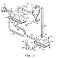
- FIG. 2 a somewhat modified apparatus 47 is shown which is generally similar to that shown in FIG. 1 and described above.
- effluent ducts 48 and 49 do not have an exhaust fan, but merge to a common duct 50 which directly connects to the air filter housing 31.
- the air outlet duct 51 does not have an exhaust fan but is directly connected to the air filter housing 31.
- Air exhaust is provided by an exhaust fan 52 connected to the plenum 32 by an exhaust duct 53, and having an outlet duct 54.
- the chute 41 is utilized to return the released fibers to the situs where fibers are discharged from the collection chamber.
- the exhaust gases from the cyclone are driven to the air filter 30 where they are filtered further in the air filter and released to the atmosphere.
- the fibers carried to the cyclone exhaust fan are released to fall downwardly where they encounter inclined slide or chute 41.
- the residual fibers conveyed in the ducts 29 and 40 are filtered out on the belt 36 on the filter 30 and are removed intermittently by the conveyor belt 36.
- the filter 30 is formed of cement block walls with metal supporting structures, although it can alternatively be formed entirely of metal.
- the system has a movable floor comprising the belt 36 which is loaded with mineral fiber felt for the filtering media, and the waste gases are filtered through the felt and into the atmosphere.
- the operation of the belt is intermittent and is moved and advanced as the filter media comprising mineral fiber felt is replaced.
- the filter 30 comprises a means of removing the small quantities of air borne particulate fiber present in the exhaust gases.
- the device illustrated is one embodiment, however, any suitable filter including those available commercially work equally well.
- the benefits obtained by the use of the present apparatus are that of immediate yield increase. Additionally, the cost of production was reduced and the fiber quality of the fibers recovered from the cyclone mixer were even better than the main normal product returning directly from the collection chambers. As a further improvement, the use of the inclined fiber transport slide or chute enables the fiber returned from the cyclone mixer to be directly returned to the fibers received from the collection chambers and the entire output directly bagged.
Landscapes
- Chemical & Material Sciences (AREA)
- Engineering & Computer Science (AREA)
- Chemical Kinetics & Catalysis (AREA)
- Life Sciences & Earth Sciences (AREA)
- General Life Sciences & Earth Sciences (AREA)
- Geochemistry & Mineralogy (AREA)
- Manufacturing & Machinery (AREA)
- Materials Engineering (AREA)
- Organic Chemistry (AREA)
- Cyclones (AREA)
- Spinning Methods And Devices For Manufacturing Artificial Fibers (AREA)
Applications Claiming Priority (2)
| Application Number | Priority Date | Filing Date | Title |
|---|---|---|---|
| US06/677,728 US4576620A (en) | 1984-12-04 | 1984-12-04 | Apparatus for the production of mineral fibers having supplemental collection chamber exhaust |
| US677728 | 1984-12-04 |
Publications (2)
| Publication Number | Publication Date |
|---|---|
| EP0184343A2 true EP0184343A2 (de) | 1986-06-11 |
| EP0184343A3 EP0184343A3 (de) | 1988-05-11 |
Family
ID=24719886
Family Applications (1)
| Application Number | Title | Priority Date | Filing Date |
|---|---|---|---|
| EP85308222A Withdrawn EP0184343A3 (de) | 1984-12-04 | 1985-11-12 | Vorrichtung für die Herstellung von Mineralfasern mit zusätzlichem Abscheider in der Abgasleitung der Sammelkammer |
Country Status (3)
| Country | Link |
|---|---|
| US (1) | US4576620A (de) |
| EP (1) | EP0184343A3 (de) |
| CA (1) | CA1271038A (de) |
Families Citing this family (3)
| Publication number | Priority date | Publication date | Assignee | Title |
|---|---|---|---|---|
| FR2663049B1 (fr) * | 1990-06-12 | 1994-05-13 | Isover Saint Gobain | Recyclage de produits fibreux dans une ligne de production de matelas a partir de fibres. |
| US20140076000A1 (en) * | 2012-09-20 | 2014-03-20 | Timothy James Johnson | Apparatus and method for air flow control during manufacture of glass fiber insulation |
| RU2731241C1 (ru) * | 2019-12-10 | 2020-08-31 | Владислав Михайлович Святский | Волокнообразующее устройство |
Family Cites Families (5)
| Publication number | Priority date | Publication date | Assignee | Title |
|---|---|---|---|---|
| US2016401A (en) * | 1933-03-06 | 1935-10-08 | Owens Illinois Glass Co | Caked glass wool and its manufacture |
| US2450511A (en) * | 1945-01-24 | 1948-10-05 | Eagle Picher Co | Apparatus for diverting mineral wool from blow rooms |
| US3442633A (en) * | 1964-01-02 | 1969-05-06 | Walter Merton Perry | Method and apparatus for conveying and for treating glass fibers |
| US4230471A (en) * | 1973-03-30 | 1980-10-28 | Saint-Gobain Industries | Suppression of pollution in mineral fiber manufacture |
| US3883334A (en) * | 1974-05-23 | 1975-05-13 | L C Cassidy & Son Inc | Mineral fiber production method and apparatus |
-
1984
- 1984-12-04 US US06/677,728 patent/US4576620A/en not_active Expired - Fee Related
-
1985
- 1985-11-12 EP EP85308222A patent/EP0184343A3/de not_active Withdrawn
- 1985-12-02 CA CA000496649A patent/CA1271038A/en not_active Expired
Also Published As
| Publication number | Publication date |
|---|---|
| US4576620A (en) | 1986-03-18 |
| EP0184343A3 (de) | 1988-05-11 |
| CA1271038A (en) | 1990-07-03 |
Similar Documents
| Publication | Publication Date | Title |
|---|---|---|
| US4457043A (en) | Sweeper particularly for collecting dust-like material, and the utilization thereof | |
| RU2456099C2 (ru) | Установка пневмовакуумной сепарации сыпучих материалов | |
| US3827955A (en) | Cleaning waste gases containing hydrogen fluorides from an electrolytic furnace for aluminum production | |
| US5342427A (en) | Apparatus for cullet preheating and polluting emission reduction in the glass manufacturing process | |
| US20010047698A1 (en) | Method for the separation and recycling of hot fines in hot briquetting of reduced iron | |
| KR910007563B1 (ko) | 방적섬유 원료 정면장치 | |
| US4576620A (en) | Apparatus for the production of mineral fibers having supplemental collection chamber exhaust | |
| US3973762A (en) | Sintering process and apparatus | |
| SU937133A2 (ru) | Установка дл абразивной обработки поверхностей бетонных изделий | |
| AU682518B2 (en) | Method and device for separating heavy particles from a particulate material | |
| US2680493A (en) | Apparatus for removing fume from electric furnace gases | |
| CN213421751U (zh) | 一种兰炭粉加工用烘干系统 | |
| US3133319A (en) | Process and apparatus for cleaning, separating and felting fibrous materials | |
| JPS61146727A (ja) | フアイバ装置 | |
| RU2004440C1 (ru) | Установка дл приготовлени глинопорошка | |
| RU236485U1 (ru) | Вибрационный питатель тарного стеклобоя | |
| JP2002126563A (ja) | 乾式製砂装置 | |
| SU1586794A1 (ru) | Лини дл переработки влажных полезных ископаемых | |
| US3110483A (en) | Method of and apparatus for removing alkali from cement system | |
| GB2167681A (en) | Separator | |
| US3313229A (en) | Gas hood | |
| RU2063387C1 (ru) | Устройство для очистки и сбора минерального штапельного волокна в процессе его раздува | |
| JPS6117455A (ja) | セメント製造プロセスで用いられる除塵装置を備えたクリンカー冷却器 | |
| SU1504188A1 (ru) | Устройство дл перегрузки сыпучих материалов | |
| JPS6318422Y2 (de) |
Legal Events
| Date | Code | Title | Description |
|---|---|---|---|
| PUAI | Public reference made under article 153(3) epc to a published international application that has entered the european phase |
Free format text: ORIGINAL CODE: 0009012 |
|
| AK | Designated contracting states |
Kind code of ref document: A2 Designated state(s): AT BE CH DE FR GB IT LI LU NL SE |
|
| PUAL | Search report despatched |
Free format text: ORIGINAL CODE: 0009013 |
|
| AK | Designated contracting states |
Kind code of ref document: A3 Designated state(s): AT BE CH DE FR GB IT LI LU NL SE |
|
| 17P | Request for examination filed |
Effective date: 19880929 |
|
| 17Q | First examination report despatched |
Effective date: 19890615 |
|
| STAA | Information on the status of an ep patent application or granted ep patent |
Free format text: STATUS: THE APPLICATION IS DEEMED TO BE WITHDRAWN |
|
| 18D | Application deemed to be withdrawn |
Effective date: 19891227 |
|
| RIN1 | Information on inventor provided before grant (corrected) |
Inventor name: PORTER, WILLIAM FLOYD Inventor name: JOHNSON, DWIGHT EDWARD Inventor name: PORTER, MICHAEL J. |