EP0184419B1 - Système interactif d'affichage tramé - Google Patents
Système interactif d'affichage tramé Download PDFInfo
- Publication number
- EP0184419B1 EP0184419B1 EP85308767A EP85308767A EP0184419B1 EP 0184419 B1 EP0184419 B1 EP 0184419B1 EP 85308767 A EP85308767 A EP 85308767A EP 85308767 A EP85308767 A EP 85308767A EP 0184419 B1 EP0184419 B1 EP 0184419B1
- Authority
- EP
- European Patent Office
- Prior art keywords
- pel
- run
- pels
- runs
- colour
- Prior art date
- Legal status (The legal status is an assumption and is not a legal conclusion. Google has not performed a legal analysis and makes no representation as to the accuracy of the status listed.)
- Expired - Lifetime
Links
Images




Classifications
-
- G—PHYSICS
- G06—COMPUTING OR CALCULATING; COUNTING
- G06T—IMAGE DATA PROCESSING OR GENERATION, IN GENERAL
- G06T11/00—Two-dimensional [2D] image generation
- G06T11/40—Filling planar surfaces by adding surface attributes, e.g. adding colours or textures
-
- G—PHYSICS
- G06—COMPUTING OR CALCULATING; COUNTING
- G06T—IMAGE DATA PROCESSING OR GENERATION, IN GENERAL
- G06T15/00—Three-dimensional [3D] image rendering
- G06T15/50—Lighting effects
- G06T15/80—Shading
Definitions
- This invention relates to interactive raster display systems and more particularly to a method for ascertaining the boundary of an arbitrarily-shaped closed polygon filled with a first colour-coded pel pattern and for filling the ascertained polygon with a second colour-coded pel pattern in such a system.
- Prior art interactive buffered raster displays include low-persistence phosphor multiple gun colour cathode ray tubes (CRTs).
- CRT is the electronic medium upon which an image is painted by way of electron beam deflection and intensity modulation of its multiple coloured guns.
- Information both defining the image to be painted and providing the necessary control, is obtained from a buffer intermediate the CRT display and a stored program-controlled processor.
- the processor executes lists of graphical orders ultimately resulting in the CRT painted image.
- the processor causes bit values in the form of a multibit code to be stored in a counterpart location in the buffer.
- the multibit code termed a "pel" consists of an x,y position coordinate and a colour number or value.
- the bits are used to index a translate table which converts them into a larger number of bits.
- This larger number of bits drives designated red, green, and blue digital-to-analog converters actually modulating the multigun CRT beam intensities.
- 457-458 for ascertaining the shape of the polygon to be filled involves finding the intersections of a scan line with all the edges of a polygon, sorting the intersections by an increasing x coordinate, and filling in all pels between pairs of intersections.
- US-A-4,334,274 describes a method for resolving ambiguous pels or pixels bordering a black/white object by edge-detecting the object and overlaying said edge with logical positive and negative object images. This permits ascertaining ambiguous pels. Thereafter, there is involved the step of either shrinking or expanding the black or white fill in the region of any ambiguous pel in order to conform to the detected object edge.
- an interactive raster display system including a multigun colour display monitor 5, a keyboard 3 with programmable function keys, a mix of RAM and ROM based memory 7, one or more DASDs 9 attachable through an adaptor 2, and a stored program-controlled microprocessor 1 interconnecting the monitor 5, keyboard 3, memory 7, and adapter 2.
- One configuration for example includes an IBM 5153 Colour Monitor with an IBM 4910 Colour Adaptor Card, an IBM 5160 Systems Unit, an IBM PC keyboard, and a 13,335cm (51/4 inch) floppy disk drive with a PC adaptor.
- the refreshed raster display portion (Fig. 1 B) of this system comprises a display buffer 13, a translate table 15, the processor 1, and a refresh controller 11.
- the processor 1 constructs an image of pels and writes them into the display buffer 13 over paths 27 and 29. Furthermore, processor 1 also may access and alter the contents of translation table 15 over paths 23 and 25.
- the refresh controller actually accesses consecutive locations in buffer 13.
- the colour values of the extracted pels are in turn converted by the translate table and applied to the red, green, and blue guns 17, 19 and 21 of the CRT of the colour monitor 5.
- the x,y coordinates associated with the extracted pel control the electron beam deflection of the CRT.
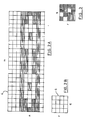
- a black and white raster-coded object is shown in Figure 2A, representing a bit map such as might appear in the refresh buffer or on the display face.
- the entire m x n array 4 of pels is termed a "domain".
- an "object” is defined as the replication of a reference pattern in the domain, then several objects are included in the domain of Figure 2A. These comprise considering white on black, a white chain-linked object in a black field and considering black on white a black band having a chain link aperture set in a white field. In either case, the object is closed or bounded and consists of runs of contiguous pels of like colour in the raster scan line direction.
- each pel may assume one of three, four, or more colour values.
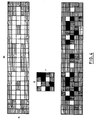
- the difficulty of ascertaining the "boundary" of an object formed from multiple contiguous arrays of colour complexity is greater than that of patterns of solid colour, e.g. Figure 2A. This is illustrated in Figure 4 where the chain-linked object is somewhat masked by being embedded or formed from the colour rich patterns.
- a run is operationally defined as the colour value match of q consecutive pels on the ith row of a first or reference pattern with q consecutive pels on the jth row or raster scan line of a domain.
- each row of the reference pattern consists of pels of like colour value so that for a given raster scan line of the domain, a run would exhibit contiguous pels of the same colour value.
- a run would require the replication on a pel comparison match basis.
- Figure 9B where the reference pattern consists of a r x q array of a pattern of red, white, and blue pels.
- the top row of the reference pattern is coded as blue-white blue-white and "runs" in the domain (Fig. 9A) can be found in the first, fourth, and seventh domain rows from the top.
- the second reference pattern row is coded as white-red white- white. This appears without ambiguity in the second, third, fifth, sixth, eighth and ninth rows of the domain.
- a raster scan line may have one or more runs.
- the leftmost pel position of a run is labelled for illustration by letters. In the preferred embodiment, the location of a run is defined by the position of the leftmost pel position.
- the first method step contemplates identifying the pattern constituting the object.
- the pattern is a r x q white pel array. It should be recalled that in the IBM Technical Disclosure Bulletin article referred to above, neighbouring cells are recursively coloured starting with the colour value of a single seed cell. This recursive colouring continues until a border cell of an object was detected. While attractively simple, this can not use replacement colour-coded patterns more complex than a single pel for the algorithm because there can be no guarantee of a termination of the identify and filling of cells on the fly where the replacement colour-coded pattern corresponded at any point to the original colour-coded pattern.
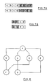
- FIG 8 there is shown a connected graph representation of runs identified in the white object depicted in Figure 5. Each run is represented by a counterpart labelled vertex. Line-to-line contiguity between runs is shown by an edge connecting a pair of vertices. This means that the determination of the area of a closed polygon by scanning contiguous runs is the same as dealing with the graph and visiting the vertices and connecting edges in a systematic fashion.
- the determination of the polygon area formed by unique contiguous runs is equivalent to presenting such runs as a graph and then traversing the graph such that each node is visited only once.
- a recursive (depth first) and non-recursive (parent-child) traverse are discussed.
- a depth first search which is a generalization of the preorder traversal of a tree, is one important technique.
- a depth first search works by selecting one vertex v as a start vertex and marking v as visited. Then each unvisited vertex adjacent to v is searched in turn, using depth first search recursively. Once all vertices that can be reached from v have been visited, the search of v is complete. If some vertices remain unvisited, an unvisited vertex is selected as a new start vertex. This process is repeated until all the vertices have been visited.
- the name "depth first search” is apt because the technique continues searching in the forward (deeper) direction as long as possible.
- a depth first search selects some unexplored edge connecting x to y. If y has been visited, the procedure looks for another unexplored edge connected to x. If y has not been visited, then the procedure marks y as visited and initiates a new search at y. After completing the search through all paths beginning at y, the search returns to x, the vertex from which y was first visited. The process of selecting unexplored edges emanating from x is then continued until all edges from x have been explored.
- An adjacency list can be used to represent the vertices adjacent to vertex x, and a data structure such as an array mark, whose elements are chosen from (visited, unvisited), can be used to determine whether a vertex has been previously visited.
- the depth first search is a traversal of all connected vertices in a graph and marking a memory or list to indicate those vertices visited.
- the method of the invention utilizes three lists: a permanent final list and a temporary parent and child list.
- a graph traversing search or scan is invoked.
- a conventional left scan is made until the lefthand end of a run is identified in step 102 and labelled, in this case a.
- a scan is made to determine the length moving from left to right. In this case, run starting at a is nine pels long. It is then placed on the "parent list" in step 103 and on the "final list” in step 104.
- step 105 it is next desirable to identify in step 105 the contiguous runs or, as set out above, those identif ied as “descendants” or "children".
- the "children" of run a are the contiguous runs b, c, d, and e. Because the descendants are found not to be on the "final list” in step 106 , they are therefore added both to the "final list” in step 107 and the "child list” in step 108.
- step 109 it is determined whether the parent has any more children. If so, step 105 is repeated. If not, the next stage is reached.
- step 111 it is determined in step 111 whether there are any parent runs added to the final list. If so, step 105 is used.
- the child or descendant (contiguous) runs associated with run c are processed. These are runs a and g. Because run a is already on the "final list", it does not reappear on the "child list”. Thus, only run g appears on the "child list”. At this point, runs b, c, d, e, f and g are on the "final list”.
- runs contiguous to run d are processed, namely runs f and a are the contiguous descendents of run D. Because they are already on the "final list", there is no change.
- step 110 the "child list” runs of f and g are transferred to the "parent list”. There are no descendant runs because runs b, c, d, and e are already on the "final list”.
- step 111 now indicates no new parent runs added to the final list
- the final list now completely describes the object to be filled in step 112. The procedure terminates upon exhaustion of the "parent list”.
- step 1 two run counters are created. These are the current and previous run counters and are both set to zero.
- the workspace buffer is divided into two equal parts where list 1 stores the screen starting byte offsets (1 word), and list 2 stores the byte length of the run, the end pel offset and the start pel offset.
- list 1 and list 2 pointers are set to the top of lists 1 and 2 respectively.
- the list 2 pointer for a run is equal to the list 1 pointer for the run plus half the workspace buffer length.
- step 2 the starting byte offset is set to the beginning column offset, and the length and the start pel offsets are set to zero.
- the cursor travels left from the beginning column offset to find the run's starting location of the run. First, it must be ascertained whether the pattern matches to the byte boundary. If so, set the byte-match flag is set high.
- step 3 because a byte match has failed (righthand of Fig. 7A), it is necessary to find the pel offset and the byte offset to the start of the run. If the byte-match flag from step 2 is greater than zero, then it is necessary to ascertain whether three, two or lastly, one of the Regen pels matches the background pattern looking left from the start byte offset. The start pel offset is found to be one if the closest three pels match, two if the closest two pels match (Fig. 7B), and three if the closest pel matches from the start byte offset. If a non-zero pel offset is found, then the start byte is decremented and the byte length incremented.
- step 2 If the byte-match flag from step 2 is equal to zero, a different procedure is followed. In this case, it is first necessary to ascertain whether the two closest pels match the background pattern looking left from the start byte offset. If the two closest pels do not match the background, then it is necessary to determine whether the closest pel matches. If no match is found, then the start pel position is the remainder when the beginning column offset is divided by four. If a match is found, then the starting pel position is decremented by the number of pels that matched.
- step 4 travel rightward on a byte-match basis to determine that the end of the run requires that the end pel offset be set to 3 and the byte-match flag set to low. From the beginning column offset, travel towards the right. Determine whether the pattern matches to the byte boundary. If so, it is necessary to set the byte-match flag high and then begin to match the background pattern with the Regen buffer on a byte level and each time an entire byte matches, then increment the byte length. This continues until a match fails or the right edge of the screen is reached. At this point, the run length has been found unless modified by step 5.
- step 5 travel is rightward on a pel-match basis to determine the end of the run. Because the byte-match failed, it is necessary to find the end offset of the pel and the length of the run byte. If the byte-match flag from step 4 is greater than zero, then see if three, two, or lastly, one Regen pel matches the background pattern looking left beginning at the position equal to the start byte plus the length of the run byte plus one. If a match is found, then it is necessary to increment the byte length. The end pel offset is found to be two if three pels match, one if two pels match, and zero if one pel matches.
- step 4 If the byte-match flag from step 4 is equal to zero, a different procedure is followed. At this point, it is necessary to determine whether the two closest pels match the background pattern looking right from the beginning column offset divided by four. If they do not match, then it is necessary to check if the closest pel matches.
- the end pel offset is equal to the beginning pel offset from step 3 plus the number of pels that matched.
- step 6 it is necessary to put run data on list 1 and list 2. If the length of the run in pels makes for a valid run, then the starting byte offset is placed onto list 1 and the byte length of the run, and the ending and starting pel offsets onto list 2. At this point, the current run count number is incremented. Also, the current list 1 and list 2 pointers are incremented so that they point to the first empty space in their buffers. In the event that there is no more room in the buffer, then an error flag is set and a transfer made to step 15. If the previous count number is not zero, then a transfer is made to step 10.
- the dependent runs are now the ancestor or parent runs.
- the descendant or child run list becomes the ancestor or parent run list by setting the ancestor or parent run list pointers into list 1 and list 2 to the start of the descendant or child runs in list 1 and list 2. This is accomplished by backing up the pointers from the first empty space on list 1 and list 2 by the number of descendant or child runs. The pointers for the next generation of descendant or child runs continues to point to the first empty space on list 1 and list 2.
- the descendant or child run count number becomes the parent count number and the dependent count number is reset to zero.
- step 8 it is necessary to scan or look up one raster line for new child or descendant runs unless the descendant or child scan line is already at the top of the screen. This is implemented by obtaining the starting byte, starting and ending pel, and byte length of an ancestor or parent and determining the new starting byte if the ancestor or parent were one line up. Also, the beginning and ending column numbers of the run are ascertained as well as the beginning and ending byte of the entire line in the Regen buffer for one line up.
- step 9 new runs are checked. This means that if the screen pel matches the background pattern, this is treated as a new beginning point and a return is made to step 2. Otherwise, a transfer is made to step 11.
- a scan is made for new descendant or child runs from the end of the current descendant or child run.
- a skip is made to the end of the currently identified valid descendant or child run, two columns are added, an update of the trial starting byte of the next descendant or child run is performed. With respect to the latter, a check is also made to see whether this is greater than the ending column of the ancestor or parent run. If so, then a transfer is made to step 12. Otherwise, a start is made from this new starting column and a transfer to step 9 performed.
- step 11 in the event of no match, travel is made right to one pel. Since the Regen buffer pattern does not match the background pattern, travel right one pel, and an update is made of the trial starting byte of the next descendant or child run. After this, a transfer is made to step 9 unless past the end of the ancestor or parent run. In this latter event, a transfer is made to step 12.
- step 12 a scan down of one line for new descendant or child runs is made unless already at the bottom of the screen. A transfer is made to step 13, if step 12 has already once been performed. From the parent or ancestor starting byte, it is necessary to determine the new starting byte if that ancestor or parent were one line down. Also, the beginning and ending column number of the run, and the beginning and ending byte of the entire line in the Regen buffer for one line down must be recovered.
- step 13 the next ancestor or parent run is obtained. This signifies that all the descendant or child runs of the ancestor or parent run have been identified and placed on the descendant or child run list. The ancestor or parent run is no longer needed so that the previous run count is decremented by one and the parent run pointer points to the next ancestor or parent run in list 1 and list 2. After this, a transfer is made to step 8 until the previous run count is decremented to zero.
- step 14 all of the descendant or child runs have been found. Thus, all the descendants or children of all the parents or ancestors have been found and put on the run list. A transfer is made to step 7 until the current run list contains zero runs.
- step 15 all runs are written to the screen. This means that all runs have been identified. Thus, beginning at the top of list 1, all the runs can be filled with the fill pattern. The fill pattern is justified to the top lefthand corner of the screen and repeated as many times as necessary in order to fill the interior region of the ascertained shape.
- the following table sets out an assembly level code sequence instructing the processor portion of an interactive raster display system in the execution of the method steps of this invention.
- the syntax for assembly code is from left to right:
Landscapes
- Engineering & Computer Science (AREA)
- Physics & Mathematics (AREA)
- General Physics & Mathematics (AREA)
- Theoretical Computer Science (AREA)
- Computer Graphics (AREA)
- Image Generation (AREA)
- Image Analysis (AREA)
Claims (2)
Applications Claiming Priority (2)
| Application Number | Priority Date | Filing Date | Title |
|---|---|---|---|
| US679666 | 1984-12-07 | ||
| US06/679,666 US4754488A (en) | 1984-12-07 | 1984-12-07 | Method for ascertaining and filling of bounded areas of a colored raster display |
Publications (3)
| Publication Number | Publication Date |
|---|---|
| EP0184419A2 EP0184419A2 (fr) | 1986-06-11 |
| EP0184419A3 EP0184419A3 (en) | 1989-03-22 |
| EP0184419B1 true EP0184419B1 (fr) | 1993-08-11 |
Family
ID=24727842
Family Applications (1)
| Application Number | Title | Priority Date | Filing Date |
|---|---|---|---|
| EP85308767A Expired - Lifetime EP0184419B1 (fr) | 1984-12-07 | 1985-12-02 | Système interactif d'affichage tramé |
Country Status (5)
| Country | Link |
|---|---|
| US (1) | US4754488A (fr) |
| EP (1) | EP0184419B1 (fr) |
| JP (1) | JPH0664619B2 (fr) |
| CA (1) | CA1238731A (fr) |
| DE (1) | DE3587522T2 (fr) |
Families Citing this family (20)
| Publication number | Priority date | Publication date | Assignee | Title |
|---|---|---|---|---|
| US4837710A (en) * | 1985-12-06 | 1989-06-06 | Bull Hn Information Systems Inc. | Emulation attribute mapping for a color video display |
| US4878181A (en) * | 1986-11-17 | 1989-10-31 | Signetics Corporation | Video display controller for expanding monochrome data to programmable foreground and background color image data |
| US4837847A (en) * | 1987-02-03 | 1989-06-06 | Canon Kabushiki Kaisha | Image processing apparatus |
| US5051928A (en) * | 1987-12-28 | 1991-09-24 | Dubner Computer Systems, Inc. | Color correction for video graphics system |
| EP0356262B1 (fr) * | 1988-08-26 | 1995-07-12 | Canon Kabushiki Kaisha | Appareil de traitement d'images |
| JPH0277889A (ja) * | 1988-09-14 | 1990-03-16 | Ricoh Co Ltd | 図形塗りつぶし方式 |
| JPH02235185A (ja) * | 1989-03-09 | 1990-09-18 | Ricoh Co Ltd | 図形再生方法 |
| US5254981A (en) * | 1989-09-15 | 1993-10-19 | Copytele, Inc. | Electrophoretic display employing gray scale capability utilizing area modulation |
| US5153748A (en) * | 1989-09-28 | 1992-10-06 | Eastman Kodak Company | Detection of gaps in scanned images |
| US5131049A (en) * | 1989-12-08 | 1992-07-14 | Xerox Corporation | Identification, characterization, and segmentation of halftone or stippled regions of binary images by growing a seed to a clipping mask |
| US5781666A (en) * | 1990-04-17 | 1998-07-14 | Canon Kabushiki Kaisha | Image processing method and apparatus suitable for both high-resolution and low-resolution image data |
| GB9020082D0 (en) * | 1990-09-14 | 1990-10-24 | Crosfield Electronics Ltd | Methods and apparatus for defining contours in coloured images |
| FR2667969B1 (fr) * | 1990-10-16 | 1995-01-27 | Sextant Avionique | Procede de coloriage sur un ecran a matrice de points. |
| JP2892898B2 (ja) * | 1992-04-17 | 1999-05-17 | インターナショナル・ビジネス・マシーンズ・コーポレイション | ウインドウ管理方法及びラスタ表示ウインドウ管理システム |
| US5542055A (en) * | 1993-05-28 | 1996-07-30 | International Business Machines Corp. | System for counting the number of peripheral buses in each hierarch connected to primary bus for creating map of peripheral buses to locate peripheral devices |
| US5640468A (en) * | 1994-04-28 | 1997-06-17 | Hsu; Shin-Yi | Method for identifying objects and features in an image |
| US5912994A (en) * | 1995-10-27 | 1999-06-15 | Cerulean Colorization Llc | Methods for defining mask of substantially color-homogeneous regions of digitized picture stock |
| JP4181703B2 (ja) * | 1999-09-02 | 2008-11-19 | キヤノン株式会社 | 光電変換装置 |
| US6897869B1 (en) * | 1999-10-25 | 2005-05-24 | International Business Machines Corporation | System and method for filling a polygon |
| TWI610292B (zh) * | 2015-11-19 | 2018-01-01 | 瑞鼎科技股份有限公司 | 驅動電路及其運作方法 |
Family Cites Families (10)
| Publication number | Priority date | Publication date | Assignee | Title |
|---|---|---|---|---|
| US3987412A (en) * | 1975-01-27 | 1976-10-19 | International Business Machines Corporation | Method and apparatus for image data compression utilizing boundary following of the exterior and interior borders of objects |
| JPS5510621A (en) * | 1978-07-07 | 1980-01-25 | Copyer Co Ltd | Method and device for discrimination between inside and outside bordering closed curve |
| US4318121A (en) * | 1980-05-06 | 1982-03-02 | Jason Taite | Interior decor composition and display systems |
| US4528642A (en) * | 1982-04-12 | 1985-07-09 | Tektronix, Inc. | Completing a fill pattern inside a redrawn panel outline |
| JPS5930179A (ja) * | 1982-08-10 | 1984-02-17 | Agency Of Ind Science & Technol | パタ−ンの線分近似方式 |
| US4646076A (en) * | 1983-04-27 | 1987-02-24 | Sperry Corporation | Method and apparatus for high speed graphics fill |
| US4667306A (en) * | 1983-07-20 | 1987-05-19 | Ramtek Corporation | Method and apparatus for generating surface-fill vectors |
| US4616220A (en) * | 1983-08-22 | 1986-10-07 | Burroughs Corporation | Graphics display comparator for multiple bit plane graphics controller |
| US4521909A (en) * | 1983-10-04 | 1985-06-04 | Wang Laboratories, Inc. | Dual level pattern recognition system |
| US4646078A (en) * | 1984-09-06 | 1987-02-24 | Tektronix, Inc. | Graphics display rapid pattern fill using undisplayed frame buffer memory |
-
1984
- 1984-12-07 US US06/679,666 patent/US4754488A/en not_active Expired - Fee Related
-
1985
- 1985-06-20 CA CA000484633A patent/CA1238731A/fr not_active Expired
- 1985-11-07 JP JP60248164A patent/JPH0664619B2/ja not_active Expired - Lifetime
- 1985-12-02 EP EP85308767A patent/EP0184419B1/fr not_active Expired - Lifetime
- 1985-12-02 DE DE85308767T patent/DE3587522T2/de not_active Expired - Fee Related
Also Published As
| Publication number | Publication date |
|---|---|
| JPH0664619B2 (ja) | 1994-08-22 |
| DE3587522T2 (de) | 1994-03-17 |
| DE3587522D1 (de) | 1993-09-16 |
| CA1238731A (fr) | 1988-06-28 |
| JPS61138378A (ja) | 1986-06-25 |
| US4754488A (en) | 1988-06-28 |
| EP0184419A3 (en) | 1989-03-22 |
| EP0184419A2 (fr) | 1986-06-11 |
Similar Documents
| Publication | Publication Date | Title |
|---|---|---|
| EP0184419A2 (fr) | Système interactif d'affichage tramé | |
| EP0104329B1 (fr) | Méthode et dispositif pour éditer un dispositif d'affichage à balayage à trame | |
| US5115402A (en) | Scan-conversion process and processor for converting a graphic primitive to a pixel map | |
| EP0656608B1 (fr) | Procédé et appareil pour le placement d'annotations sur un écran sans chevauchement | |
| US5461712A (en) | Quadrant-based two-dimensional memory manager | |
| US5333254A (en) | Methods of centering nodes in a hierarchical display | |
| US5504853A (en) | System and method for selecting symbols and displaying their graphics objects in a detail window | |
| US5509110A (en) | Method for tree-structured hierarchical occlusion in image generators | |
| KR960012669B1 (ko) | 앤티-에일리어즈드 다각형을 렌더링하기 위한 방법 및 장치 | |
| US4451825A (en) | Digital data display system | |
| GB2167927A (en) | Data transfer method | |
| EP0607136B1 (fr) | Systeme infographique a mise a jour delimitee | |
| KR0161712B1 (ko) | 디지탈화상에 임시 및 참라벨을 할당하는 방법 및 장치 | |
| EP0043703B1 (fr) | Dispositif de commande d'un système d'affichage à balayage à trame | |
| EP0607131B1 (fr) | Systeme et procede de sortie graphique | |
| US5696539A (en) | Method for matching colors of data displayed on connected computer systems | |
| CA1230688A (fr) | Methode de mise a l'echelle des caracteres dans un systeme d'affichage de vecteurs de frappe | |
| US5517607A (en) | Graphic processing apparatus utilizing a CAD system | |
| US5068803A (en) | Method and apparatus for filling contours in digital typefaces | |
| EP0566387B1 (fr) | Dispositif d'affichage à balayage à trame et sa méthode de commande | |
| US5038385A (en) | Area filling method for filling an inside portion of a raster graphic obtained by developing a binary graphic described by direction codes | |
| US6097388A (en) | Method for managing non-rectangular windows in a raster display | |
| Foley | A standard computer graphics subroutine package | |
| Hanson et al. | A method of rotating areas on a raster scan graphic display | |
| Akeroyd et al. | Open Genie |
Legal Events
| Date | Code | Title | Description |
|---|---|---|---|
| PUAI | Public reference made under article 153(3) epc to a published international application that has entered the european phase |
Free format text: ORIGINAL CODE: 0009012 |
|
| AK | Designated contracting states |
Kind code of ref document: A2 Designated state(s): DE FR GB IT |
|
| 17P | Request for examination filed |
Effective date: 19861029 |
|
| PUAL | Search report despatched |
Free format text: ORIGINAL CODE: 0009013 |
|
| AK | Designated contracting states |
Kind code of ref document: A3 Designated state(s): DE FR GB IT |
|
| 17Q | First examination report despatched |
Effective date: 19910514 |
|
| GRAA | (expected) grant |
Free format text: ORIGINAL CODE: 0009210 |
|
| AK | Designated contracting states |
Kind code of ref document: B1 Designated state(s): DE FR GB IT |
|
| PG25 | Lapsed in a contracting state [announced via postgrant information from national office to epo] |
Ref country code: IT Free format text: LAPSE BECAUSE OF FAILURE TO SUBMIT A TRANSLATION OF THE DESCRIPTION OR TO PAY THE FEE WITHIN THE PRESCRIBED TIME-LIMIT;WARNING: LAPSES OF ITALIAN PATENTS WITH EFFECTIVE DATE BEFORE 2007 MAY HAVE OCCURRED AT ANY TIME BEFORE 2007. THE CORRECT EFFECTIVE DATE MAY BE DIFFERENT FROM THE ONE RECORDED. Effective date: 19930811 |
|
| REF | Corresponds to: |
Ref document number: 3587522 Country of ref document: DE Date of ref document: 19930916 |
|
| ET | Fr: translation filed | ||
| PLBE | No opposition filed within time limit |
Free format text: ORIGINAL CODE: 0009261 |
|
| STAA | Information on the status of an ep patent application or granted ep patent |
Free format text: STATUS: NO OPPOSITION FILED WITHIN TIME LIMIT |
|
| 26N | No opposition filed | ||
| PGFP | Annual fee paid to national office [announced via postgrant information from national office to epo] |
Ref country code: GB Payment date: 19951127 Year of fee payment: 11 |
|
| PGFP | Annual fee paid to national office [announced via postgrant information from national office to epo] |
Ref country code: FR Payment date: 19951128 Year of fee payment: 11 |
|
| PGFP | Annual fee paid to national office [announced via postgrant information from national office to epo] |
Ref country code: DE Payment date: 19951229 Year of fee payment: 11 |
|
| PG25 | Lapsed in a contracting state [announced via postgrant information from national office to epo] |
Ref country code: GB Effective date: 19961202 |
|
| GBPC | Gb: european patent ceased through non-payment of renewal fee |
Effective date: 19961202 |
|
| PG25 | Lapsed in a contracting state [announced via postgrant information from national office to epo] |
Ref country code: FR Effective date: 19970829 |
|
| PG25 | Lapsed in a contracting state [announced via postgrant information from national office to epo] |
Ref country code: DE Effective date: 19970902 |
|
| REG | Reference to a national code |
Ref country code: FR Ref legal event code: ST |