EP0184426A2 - An improved cargo trailer - Google Patents
An improved cargo trailer Download PDFInfo
- Publication number
- EP0184426A2 EP0184426A2 EP85308792A EP85308792A EP0184426A2 EP 0184426 A2 EP0184426 A2 EP 0184426A2 EP 85308792 A EP85308792 A EP 85308792A EP 85308792 A EP85308792 A EP 85308792A EP 0184426 A2 EP0184426 A2 EP 0184426A2
- Authority
- EP
- European Patent Office
- Prior art keywords
- chassis
- trailer
- peculiar
- draw bar
- improved cargo
- Prior art date
- Legal status (The legal status is an assumption and is not a legal conclusion. Google has not performed a legal analysis and makes no representation as to the accuracy of the status listed.)
- Granted
Links
Images

Classifications
-
- B—PERFORMING OPERATIONS; TRANSPORTING
- B60—VEHICLES IN GENERAL
- B60P—VEHICLES ADAPTED FOR LOAD TRANSPORTATION OR TO TRANSPORT, TO CARRY, OR TO COMPRISE SPECIAL LOADS OR OBJECTS
- B60P1/00—Vehicles predominantly for transporting loads and modified to facilitate loading, consolidating the load, or unloading
- B60P1/04—Vehicles predominantly for transporting loads and modified to facilitate loading, consolidating the load, or unloading with a tipping movement of load-transporting element
- B60P1/30—Vehicles predominantly for transporting loads and modified to facilitate loading, consolidating the load, or unloading with a tipping movement of load-transporting element in combination with another movement of the element
- B60P1/34—Vehicles predominantly for transporting loads and modified to facilitate loading, consolidating the load, or unloading with a tipping movement of load-transporting element in combination with another movement of the element the other movement being raising or lowering
Definitions
- trailers and semi-trailers are sometimes inappropriate and practically always inconvenient for transferring goods from one vehicle to another, or from a vehicle to a storage area or vice-versa.
- This invention is concerned with an improved cargo trailer which is comprised of a chassis with at least one set of wheels, and a load assembly attached to said chassis and comprising an over-chassis and/or load container, where said trailer is peculiar insofar that it is comprised of:-
- Anchoring means are moreover provided, the ends of which are pivotally attached and linked to an anchoring point on the load assembly and to an anchoring point on the chassis.
- Figure 4 provides moreover, an enlarged view of the travelling anchorage (17) between the chassis (1) and the load container (16).
- travelling anchor point (17) is positioned at the end attachment (27c) on the load container (16).
- travelling anchor position (17) is located at the inner attachment (27a) of said load container (16).
- Travelling anchor position (17) is able to slide upon the chassis (1) and is secured thereto by means of pins (20).
- the purpose of the over-chassis is to allow a range of different load containers (16) to be used. Once the appropriate load container (16) for the purpose has been chosen, it is rigidly secured to the over-chassis.
- the over-chassis and the load container (16) shall hereinafter be called the load assembly (916).
- a trailer or semi-trailer is provided with a chassis (1), with an over-chassis optionally, and in any event with a load container (16), together with one or two sets of wheels (2), (2 bis) according to whether the equipment is a semi-trailer or a trailer proper, and a draw bar (81) for hooking up to a tractor unit.
- Chassis (1) and load assembly (916) are coupled to one another by means of scissor arm arrangement (10') which is comprised of two arms (10' 1 ) and (10' 2 ) that are pivotally joined together (101'), where arm (10' 1 ) is pivotted at (a l ) to load assembly (916), while arm (10 1 2 ) is pivotted to the chassis at (a 2 ).
- scissor arm arrangement (10') which is comprised of two arms (10' 1 ) and (10' 2 ) that are pivotally joined together (101'), where arm (10' 1 ) is pivotted at (a l ) to load assembly (916), while arm (10 1 2 ) is pivotted to the chassis at (a 2 ).
- a fluid operated cylinder (10) is fitted onto said scissor arm arrangement (10') and pivotted thereto at (a3) and (a4).
- said cylinder (10) exerts a thrust upon either of arms (10 ,1 ), it causes load assembly (916) to swivel about pivots (27) with chassis (1), and thus make load assembly (916) adopt the tipped position with respect to chassis (1).
- Hydro-pneumatic cylinder (10) provides a telescopic arrangement whereby with a minimal space requirement, all working positions can be obtained between the load container (16) and the over-chassis or load container (16) alone if appropriate with respect to the chassis (1).
- the load assembly (916) possesses three fixed anchorage points (27a), (27b), (27c) at its rear, of which the middle one (27b) is the highest and takes the pivotal joints.
- Chassis (1) possesses at its rear an arm (3) which is pivotted at (31) to chassis (1), and is comprised of two parts (3a) and (3b) that are telescopically assembled together.
- a second fluid operated cylinder (4) is also provided, and is pivotted at(41) to the chassis (1), and at (42) to the arm (3).
- Chassis (1) also embodies a fixed anchorage point (28) which is prolonged towards the bottom of same, and is located at the back of the rear set of wheels (2).
- chassis (1) can turn with respect to pivot (4') in the set of wheels (2), and so there is no need of any assistance for the various load positions of cylinder (4), and instead use is made of a head (7) attached to chassis (1), to which a hydraulic cylinder (8) is pivotally joined, the opposite end of same being secured to the tractor unit draw bar (81).
- the draw bar (81) on the trailer or semi-trailer is pivotted at (811) to the set of steering wheels (2 bis) which are capable of turning in a horizontal plane.
- Draw bar (81) is moreover associated with the main chassis (1) by means of device (7) which is capable of positioning the draw bar assembly (81) and set of wheels (2 bis) in relation to said main chassis (1) to fix it, or to release them and thus allow the aforementioned motion of the steering wheels (2 bis) and the draw bar (81) in the horizontal plane.
- Said device (70) ( Figure 1) is comprised of two bodies (71) and (72), which are assembled telescopically one upon the other.
- Body (71) is pivotted at its free end (74) to the trailer or semi-trailer chassis (1).
- Body (72) is pivotted at its free end (73) to the draw bar (81).
- Body (71) possesses a plurality of holes (711) arranged in line with one another.
- Body (72) possesses a plurality of holes (721) arranged in line with one another.
- device (70) may be fluid operated by means of a hydraulic or pneumatic cylinder, and here it is necessary to pivot its body (72) to the draw bar (81) at (73), and its plunger to the chassis (1) at (74), or vice-versa.
Landscapes
- Engineering & Computer Science (AREA)
- Transportation (AREA)
- Mechanical Engineering (AREA)
- Vehicle Body Suspensions (AREA)
- Signal Processing For Digital Recording And Reproducing (AREA)
- Body Structure For Vehicles (AREA)
- Agricultural Machines (AREA)
- Motorcycle And Bicycle Frame (AREA)
- Superconductors And Manufacturing Methods Therefor (AREA)
- Crystals, And After-Treatments Of Crystals (AREA)
- Gas-Filled Discharge Tubes (AREA)
- Production Of Liquid Hydrocarbon Mixture For Refining Petroleum (AREA)
- Disintegrating Or Milling (AREA)
- Ceramic Products (AREA)
- Vehicle Cleaning, Maintenance, Repair, Refitting, And Outriggers (AREA)
- Organic Insulating Materials (AREA)
- Polyoxymethylene Polymers And Polymers With Carbon-To-Carbon Bonds (AREA)
Abstract
Description
- Over a relatively short period of time, transport work of all kinds has been enormously facilitated thanks to both vehicles as well as goods transfer areas having been adequately conditioned.
- Nonetheless, trailers and semi-trailers are sometimes inappropriate and practically always inconvenient for transferring goods from one vehicle to another, or from a vehicle to a storage area or vice-versa.
- One of the problems that arises and where attempts are made to find a solution is that only angular and/or linear motion is required of the trailer chassis in all the working positions of the trailer and the load, and its wheels never lose contact with the ground, while sometimes it is achieved that said motions disappear.
- With this improvement, it is possible to ensure that the centre of gravity of the trailer or semi-trailer shifts very little from one position to another even when such trailer or semi-trailer adopts one or another working position, and this is because the chassis and wheels undergo minimal travel.
- This invention is concerned with an improved cargo trailer which is comprised of a chassis with at least one set of wheels, and a load assembly attached to said chassis and comprising an over-chassis and/or load container, where said trailer is peculiar insofar that it is comprised of:-
- a) A scissor arm arrangement where the arms are pivotally joined to one another at one end, while at the other end, one of them is pivotally attached to the load assembly and the other is pivotally attached to the chassis;
- b) A fluid operated cylinder that is pivotally linked by at least one of its ends to one of the ends of the scissor arm arrangement;
- c) At least one anchoring point on the rear portion of the load assembly, and at least one anchoring point on the rear portion of the chassis.
- Anchoring means are moreover provided, the ends of which are pivotally attached and linked to an anchoring point on the load assembly and to an anchoring point on the chassis.
- Figure 1 is an enlarged view of a positioning device (70) on the draw bar (81) for towing the trailer.
- Figure 2 shows the semi-trailer of the preceding figure in readiness for raising the load container, where it is seeking the loading or unloading height upon another vehicle (lorry or trailer), or upon a stock pile.
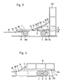
- Figure 3 depicts the semi-trailer shown in the previous figures in the fully tipped position at 90 degrees.
- Figure 4 shows another kind of trailer in its travelling position, and in it can be observed the draw bar (81) for towing by the tractor unit, and the fixed support (82) which is withdrawn whilst the semi-trailer is in motion and placed at the towing hook height so as to allow draw bar (81) to engage with tow hooks on all different kinds of tractor units.
- Figure 4 provides moreover, an enlarged view of the travelling anchorage (17) between the chassis (1) and the load container (16). For the travelling position and other positions where the trailer is tipped, except for those in which the cargo container (16) is separated from the chassis (1), travelling anchor point (17) is positioned at the end attachment (27c) on the load container (16). In the fully tipped position, where the container stands at right angles to the ground, as for example in Figure 1, travelling anchor position (17) is located at the inner attachment (27a) of said load container (16). Travelling anchor position (17) is able to slide upon the chassis (1) and is secured thereto by means of pins (20).
- The purpose of the over-chassis is to allow a range of different load containers (16) to be used. Once the appropriate load container (16) for the purpose has been chosen, it is rigidly secured to the over-chassis. The over-chassis and the load container (16) shall hereinafter be called the load assembly (916).
- A trailer or semi-trailer is provided with a chassis (1), with an over-chassis optionally, and in any event with a load container (16), together with one or two sets of wheels (2), (2 bis) according to whether the equipment is a semi-trailer or a trailer proper, and a draw bar (81) for hooking up to a tractor unit.
- Chassis (1) and load assembly (916) are coupled to one another by means of scissor arm arrangement (10') which is comprised of two arms (10'1) and (10'2) that are pivotally joined together (101'), where arm (10'1) is pivotted at (al) to load assembly (916), while arm (101 2) is pivotted to the chassis at (a2).
- A fluid operated cylinder (10) is fitted onto said scissor arm arrangement (10') and pivotted thereto at (a3) and (a4). When said cylinder (10) exerts a thrust upon either of arms (10,1), it causes load assembly (916) to swivel about pivots (27) with chassis (1), and thus make load assembly (916) adopt the tipped position with respect to chassis (1).
- Hydro-pneumatic cylinder (10) provides a telescopic arrangement whereby with a minimal space requirement, all working positions can be obtained between the load container (16) and the over-chassis or load container (16) alone if appropriate with respect to the chassis (1).
- The load assembly (916) possesses three fixed anchorage points (27a), (27b), (27c) at its rear, of which the middle one (27b) is the highest and takes the pivotal joints.
- Chassis (1) possesses at its rear an arm (3) which is pivotted at (31) to chassis (1), and is comprised of two parts (3a) and (3b) that are telescopically assembled together.
- A second fluid operated cylinder (4) is also provided, and is pivotted at(41) to the chassis (1), and at (42) to the arm (3).
- Chassis (1) also embodies a fixed anchorage point (28) which is prolonged towards the bottom of same, and is located at the back of the rear set of wheels (2).
- In the above structural arrangement, the most common working positions for which the ensuing description is given, are as follows:-
- - The travelling position, as depicted in Figure 1. When the load assembly (916) lies horizontal and is resting upon the chassis (1), arm (3) is held horizontal, and the end of its portion (3b) is pivotted at (27c) to the load assembly (916). The scissor arrangement (10') and fluid operated cylinder (10) are held in the retracted position. When draw bar (81) on the trailer or semi-trailer is hooked up, the tractor unit draws upon same in order to convey said trailer or semi-trailer in the loaded or unloaded condition from one location to another. In this position, fixed pivot (27a) is free, fixed pivot (27b) may be either free or coupled to fixed anchorage (28), and fixed pivot (27c) is attached to arm (3), although fixed pivot (27a) may also become attached, in which case fixed pivot (27c) is free.
- - The lifting postion for the purpose of tipping onto another vehicle, onto another trailer, or onto a stock pile, as depicted in Figure 2. With portion (3b) of arm (3) pivotted to fixed anchorage (27c), and with anchorage (27b) free from anchorage (28), cylinders (4) and (10) are operated to respectively make arm (3) swivel about its pivot (31) onto the chassis, and open the scissor arm arrangement (10'). The slope angle "a" will obviously depend upon the width to which scissor arms (10') open, and angle β through which arm (3) has swivelled.
- In this position, fixed pivots (27a) and (27b) are free.
- - The full tipped position at right angles or 90 degrees to the ground, as depicted in Figure 3. With portion (3b) of arm (3) pivotted at (27a), and with fixed anchorage (28) pivotted at (27b), cylinder (10) is operated thus opening the scissor arm arrangement (10') until the back face of the load assembly (916) rests upon the ground. To return to the travelling position, cylinder (10) is relieved of its load, the tip of portion (3b) on arm (3) is engaged upon fixed anchorage (27a), and cylinder (4) is operated to cause arm (3) to swivel about its pivot (31) on the chassis and thus afford an initial tipping thrust. The remainder of the tipping motion of the load assembly is brought about either through its own weight, if cylinder (10) is a single acting cylinder, or with the aid of said cylinder (10) if it is a double acting cylinder.
- In the case of the trailer as shown in Figure 4, chassis (1) can turn with respect to pivot (4') in the set of wheels (2), and so there is no need of any assistance for the various load positions of cylinder (4), and instead use is made of a head (7) attached to chassis (1), to which a hydraulic cylinder (8) is pivotally joined, the opposite end of same being secured to the tractor unit draw bar (81).
- The use of this cylinder makes differing positions of chassis (1) possible.
- In the case of the semi-trailer (Figures 2 and 3), the draw bar (81) on the trailer or semi-trailer is pivotted at (811) to the set of steering wheels (2 bis) which are capable of turning in a horizontal plane.
- Draw bar (81) is moreover associated with the main chassis (1) by means of device (7) which is capable of positioning the draw bar assembly (81) and set of wheels (2 bis) in relation to said main chassis (1) to fix it, or to release them and thus allow the aforementioned motion of the steering wheels (2 bis) and the draw bar (81) in the horizontal plane.
- Said device (70) (Figure 1) is comprised of two bodies (71) and (72), which are assembled telescopically one upon the other. Body (71) is pivotted at its free end (74) to the trailer or semi-trailer chassis (1). Body (72) is pivotted at its free end (73) to the draw bar (81).
- The above-mentioned assembly may equally be mounted the opposite way about without detracting from the essential features of the invention.
- Body (71) possesses a plurality of holes (711) arranged in line with one another.
- Body (72) possesses a plurality of holes (721) arranged in line with one another.
- When pairs of holes (711) and (721) are placed opposite each other and a pin is inserted through them, set of wheels (2 bis) and the draw bar (81) are located in position with respect to chassis (1).
- Without altering the essential features of the invention in any way, device (70) may be fluid operated by means of a hydraulic or pneumatic cylinder, and here it is necessary to pivot its body (72) to the draw bar (81) at (73), and its plunger to the chassis (1) at (74), or vice-versa.
Claims (12)
Priority Applications (1)
| Application Number | Priority Date | Filing Date | Title |
|---|---|---|---|
| AT85308792T ATE60010T1 (en) | 1984-12-04 | 1985-12-03 | LOAD TRAILER. |
Applications Claiming Priority (2)
| Application Number | Priority Date | Filing Date | Title |
|---|---|---|---|
| ES538253A ES8601038A1 (en) | 1984-12-04 | 1984-12-04 | An improved cargo trailer. |
| ES538253 | 1984-12-04 |
Publications (3)
| Publication Number | Publication Date |
|---|---|
| EP0184426A2 true EP0184426A2 (en) | 1986-06-11 |
| EP0184426A3 EP0184426A3 (en) | 1987-10-14 |
| EP0184426B1 EP0184426B1 (en) | 1991-01-16 |
Family
ID=8488257
Family Applications (1)
| Application Number | Title | Priority Date | Filing Date |
|---|---|---|---|
| EP85308792A Expired - Lifetime EP0184426B1 (en) | 1984-12-04 | 1985-12-03 | An improved cargo trailer |
Country Status (5)
| Country | Link |
|---|---|
| EP (1) | EP0184426B1 (en) |
| AT (1) | ATE60010T1 (en) |
| DE (1) | DE3581379D1 (en) |
| ES (1) | ES8601038A1 (en) |
| PT (1) | PT81600B (en) |
Cited By (2)
| Publication number | Priority date | Publication date | Assignee | Title |
|---|---|---|---|---|
| CN110154868A (en) * | 2019-07-02 | 2019-08-23 | 西藏新好科技有限公司 | A kind of transregional transfer car(buggy) of waste for animal husbandry bio-safety |
| FR3131848A1 (en) | 2022-01-19 | 2023-07-21 | L'oreal | Non-sticky stable smooth composition |
Family Cites Families (4)
| Publication number | Priority date | Publication date | Assignee | Title |
|---|---|---|---|---|
| FR1290257A (en) * | 1961-02-23 | 1962-04-13 | Agrarian or industrial vehicle for various uses | |
| GB1401949A (en) * | 1973-03-02 | 1975-08-06 | Coffey M | Container transporter |
| US3907364A (en) * | 1973-03-23 | 1975-09-23 | Bernard J Hnath | Dump vehicle |
| FR2464156A1 (en) * | 1979-08-30 | 1981-03-06 | Benac & Fils Sa | Pivoting type trailer tow-bar - pivots horizontally on floor between stops and with several lockable positions |
-
1984
- 1984-12-04 ES ES538253A patent/ES8601038A1/en not_active Expired
-
1985
- 1985-12-03 AT AT85308792T patent/ATE60010T1/en not_active IP Right Cessation
- 1985-12-03 PT PT81600A patent/PT81600B/en not_active IP Right Cessation
- 1985-12-03 DE DE8585308792T patent/DE3581379D1/en not_active Expired - Lifetime
- 1985-12-03 EP EP85308792A patent/EP0184426B1/en not_active Expired - Lifetime
Cited By (2)
| Publication number | Priority date | Publication date | Assignee | Title |
|---|---|---|---|---|
| CN110154868A (en) * | 2019-07-02 | 2019-08-23 | 西藏新好科技有限公司 | A kind of transregional transfer car(buggy) of waste for animal husbandry bio-safety |
| FR3131848A1 (en) | 2022-01-19 | 2023-07-21 | L'oreal | Non-sticky stable smooth composition |
Also Published As
| Publication number | Publication date |
|---|---|
| PT81600A (en) | 1986-01-01 |
| ES538253A0 (en) | 1985-11-01 |
| ES8601038A1 (en) | 1985-11-01 |
| EP0184426A3 (en) | 1987-10-14 |
| EP0184426B1 (en) | 1991-01-16 |
| PT81600B (en) | 1987-09-18 |
| ATE60010T1 (en) | 1991-02-15 |
| DE3581379D1 (en) | 1991-02-21 |
Similar Documents
| Publication | Publication Date | Title |
|---|---|---|
| US3355043A (en) | Truck and body connection means | |
| US3527476A (en) | Combination towing vehicle and trailer and hitch assembly therefor | |
| US4514002A (en) | Two-position bumper | |
| US4836737A (en) | Wheel lift tow assembly | |
| US4365820A (en) | Trailer connecting running gear | |
| US4144979A (en) | Beaver tail platform attachment for a trailer | |
| US5863049A (en) | Retractable and extendable wheel assembly | |
| US5803699A (en) | Apparatus and method for loading and unloading containers | |
| US6042328A (en) | Lifting device | |
| US5562391A (en) | Modular unit loading and unloading apparatus | |
| US3319811A (en) | Swing away ramp | |
| US4475740A (en) | Articulated truck/trailer combination | |
| US4513987A (en) | Self-contained lifting apparatus for low-boy trailers | |
| US4169579A (en) | Truck trailer tongue stand | |
| US3521902A (en) | Stabilizing device for trailers | |
| US3253840A (en) | Pneumatic lift system for a tractortrailer hitch | |
| EP0107746A1 (en) | Trailer connecting running gear | |
| US3338440A (en) | Farm implement carrier | |
| US5782514A (en) | Pivoting tail light bar system for movable-deck vehicle | |
| US3420390A (en) | Transfer trailer drawbar device | |
| EP0184426A2 (en) | An improved cargo trailer | |
| US3837673A (en) | Trailer backable to loading dock from either end | |
| US4278375A (en) | Trailer | |
| US4367884A (en) | Removable gooseneck for trailers | |
| US3256042A (en) | Lift mechanism |
Legal Events
| Date | Code | Title | Description |
|---|---|---|---|
| PUAI | Public reference made under article 153(3) epc to a published international application that has entered the european phase |
Free format text: ORIGINAL CODE: 0009012 |
|
| AK | Designated contracting states |
Kind code of ref document: A2 Designated state(s): AT BE CH DE FR GB IT LI LU NL SE |
|
| PUAL | Search report despatched |
Free format text: ORIGINAL CODE: 0009013 |
|
| AK | Designated contracting states |
Kind code of ref document: A3 Designated state(s): AT BE CH DE FR GB IT LI LU NL SE |
|
| 17P | Request for examination filed |
Effective date: 19880408 |
|
| 17Q | First examination report despatched |
Effective date: 19890530 |
|
| ITF | It: translation for a ep patent filed | ||
| GRAA | (expected) grant |
Free format text: ORIGINAL CODE: 0009210 |
|
| AK | Designated contracting states |
Kind code of ref document: B1 Designated state(s): AT BE CH DE FR GB IT LI LU NL SE |
|
| REF | Corresponds to: |
Ref document number: 60010 Country of ref document: AT Date of ref document: 19910215 Kind code of ref document: T |
|
| REF | Corresponds to: |
Ref document number: 3581379 Country of ref document: DE Date of ref document: 19910221 |
|
| ET | Fr: translation filed | ||
| PLBE | No opposition filed within time limit |
Free format text: ORIGINAL CODE: 0009261 |
|
| STAA | Information on the status of an ep patent application or granted ep patent |
Free format text: STATUS: NO OPPOSITION FILED WITHIN TIME LIMIT |
|
| PG25 | Lapsed in a contracting state [announced via postgrant information from national office to epo] |
Ref country code: GB Effective date: 19911203 |
|
| PG25 | Lapsed in a contracting state [announced via postgrant information from national office to epo] |
Ref country code: SE Effective date: 19911204 |
|
| PG25 | Lapsed in a contracting state [announced via postgrant information from national office to epo] |
Ref country code: LU Free format text: LAPSE BECAUSE OF NON-PAYMENT OF DUE FEES Effective date: 19911231 Ref country code: LI Effective date: 19911231 Ref country code: CH Effective date: 19911231 Ref country code: BE Effective date: 19911231 Ref country code: AT Effective date: 19911231 |
|
| 26N | No opposition filed | ||
| BERE | Be: lapsed |
Owner name: ABASCAL ZULOAGA JOSE MANUEL Effective date: 19911231 |
|
| PG25 | Lapsed in a contracting state [announced via postgrant information from national office to epo] |
Ref country code: NL Effective date: 19920701 |
|
| GBPC | Gb: european patent ceased through non-payment of renewal fee | ||
| NLV4 | Nl: lapsed or anulled due to non-payment of the annual fee | ||
| PG25 | Lapsed in a contracting state [announced via postgrant information from national office to epo] |
Ref country code: FR Effective date: 19920831 |
|
| REG | Reference to a national code |
Ref country code: CH Ref legal event code: PL |
|
| PG25 | Lapsed in a contracting state [announced via postgrant information from national office to epo] |
Ref country code: DE Effective date: 19920901 |
|
| REG | Reference to a national code |
Ref country code: FR Ref legal event code: ST |
|
| EUG | Se: european patent has lapsed |
Ref document number: 85308792.2 Effective date: 19920704 |