EP0184456A2 - Gerät und Verfahren zur Herstellung von Tintenkassetten - Google Patents
Gerät und Verfahren zur Herstellung von Tintenkassetten Download PDFInfo
- Publication number
- EP0184456A2 EP0184456A2 EP85308866A EP85308866A EP0184456A2 EP 0184456 A2 EP0184456 A2 EP 0184456A2 EP 85308866 A EP85308866 A EP 85308866A EP 85308866 A EP85308866 A EP 85308866A EP 0184456 A2 EP0184456 A2 EP 0184456A2
- Authority
- EP
- European Patent Office
- Prior art keywords
- ink
- ink container
- gasket
- flow
- support
- Prior art date
- Legal status (The legal status is an assumption and is not a legal conclusion. Google has not performed a legal analysis and makes no representation as to the accuracy of the status listed.)
- Withdrawn
Links
- 238000004519 manufacturing process Methods 0.000 title claims abstract description 13
- 239000000463 material Substances 0.000 claims abstract description 25
- 238000007789 sealing Methods 0.000 claims abstract description 14
- 239000012530 fluid Substances 0.000 claims description 35
- 238000007641 inkjet printing Methods 0.000 claims description 11
- 239000007789 gas Substances 0.000 claims description 9
- 230000007797 corrosion Effects 0.000 claims description 8
- 238000005260 corrosion Methods 0.000 claims description 8
- 230000004888 barrier function Effects 0.000 claims description 4
- 239000004698 Polyethylene Substances 0.000 claims description 3
- -1 polyethylene Polymers 0.000 claims description 3
- 229920000573 polyethylene Polymers 0.000 claims description 3
- 239000012779 reinforcing material Substances 0.000 claims description 3
- 239000004677 Nylon Substances 0.000 claims description 2
- 229920001328 Polyvinylidene chloride Polymers 0.000 claims description 2
- 238000003780 insertion Methods 0.000 claims description 2
- 230000037431 insertion Effects 0.000 claims description 2
- 229920001778 nylon Polymers 0.000 claims description 2
- 239000011118 polyvinyl acetate Substances 0.000 claims description 2
- 229920002689 polyvinyl acetate Polymers 0.000 claims description 2
- 239000005033 polyvinylidene chloride Substances 0.000 claims description 2
- 230000000903 blocking effect Effects 0.000 claims 3
- 238000004891 communication Methods 0.000 claims 2
- 238000000034 method Methods 0.000 claims 1
- 230000002093 peripheral effect Effects 0.000 abstract description 3
- 239000012611 container material Substances 0.000 abstract description 2
- 239000000523 sample Substances 0.000 description 30
- 238000010276 construction Methods 0.000 description 7
- 239000000853 adhesive Substances 0.000 description 3
- 230000001070 adhesive effect Effects 0.000 description 3
- 230000007613 environmental effect Effects 0.000 description 3
- 210000003739 neck Anatomy 0.000 description 3
- 239000004417 polycarbonate Substances 0.000 description 2
- 229920000515 polycarbonate Polymers 0.000 description 2
- 230000003014 reinforcing effect Effects 0.000 description 2
- 229910001220 stainless steel Inorganic materials 0.000 description 2
- 239000010935 stainless steel Substances 0.000 description 2
- 229920004142 LEXAN™ Polymers 0.000 description 1
- 239000004418 Lexan Substances 0.000 description 1
- 239000004020 conductor Substances 0.000 description 1
- 238000005336 cracking Methods 0.000 description 1
- 238000011161 development Methods 0.000 description 1
- HQQADJVZYDDRJT-UHFFFAOYSA-N ethene;prop-1-ene Chemical group C=C.CC=C HQQADJVZYDDRJT-UHFFFAOYSA-N 0.000 description 1
- 238000009434 installation Methods 0.000 description 1
- 229920001684 low density polyethylene Polymers 0.000 description 1
- 239000004702 low-density polyethylene Substances 0.000 description 1
- 239000002184 metal Substances 0.000 description 1
- 238000012986 modification Methods 0.000 description 1
- 230000004048 modification Effects 0.000 description 1
- 238000012544 monitoring process Methods 0.000 description 1
- 239000000123 paper Substances 0.000 description 1
- 239000004033 plastic Substances 0.000 description 1
- 229920003023 plastic Polymers 0.000 description 1
- 229920002492 poly(sulfone) Polymers 0.000 description 1
- 239000004800 polyvinyl chloride Substances 0.000 description 1
- 229920000915 polyvinyl chloride Polymers 0.000 description 1
- 238000007639 printing Methods 0.000 description 1
- 230000000717 retained effect Effects 0.000 description 1
- 230000035939 shock Effects 0.000 description 1
- 239000002904 solvent Substances 0.000 description 1
- 239000002699 waste material Substances 0.000 description 1
Images


Classifications
-
- B—PERFORMING OPERATIONS; TRANSPORTING
- B41—PRINTING; LINING MACHINES; TYPEWRITERS; STAMPS
- B41J—TYPEWRITERS; SELECTIVE PRINTING MECHANISMS, i.e. MECHANISMS PRINTING OTHERWISE THAN FROM A FORME; CORRECTION OF TYPOGRAPHICAL ERRORS
- B41J2/00—Typewriters or selective printing mechanisms characterised by the printing or marking process for which they are designed
- B41J2/005—Typewriters or selective printing mechanisms characterised by the printing or marking process for which they are designed characterised by bringing liquid or particles selectively into contact with a printing material
- B41J2/01—Ink jet
- B41J2/17—Ink jet characterised by ink handling
- B41J2/175—Ink supply systems ; Circuit parts therefor
- B41J2/17503—Ink cartridges
- B41J2/17513—Inner structure
Definitions
- the ink cartridge is for an ink jet printer of the type which supplies pressurized fluid to the cartridge for pressurizing ink within the cartridge to enhance the flow of ink from the cartridge to an ink jet printing head.
- Ink jet printers having one or more ink jet heads for projecting drops of ink onto paper or other printing medium to generate graphic images and text have become increasingly popular.
- multiple ink jet printing heads are used, with each head being supplied with ink of a different color from an associated ink cartridge.
- the print medium is attached to a rotating drum, with the ink jet heads being mounted on a travelling carriage that traverses the drum axially.
- the heads scan spiral paths over the medium, ink from the ink cartridges is delivered to the ink jet heads.
- Ink drops developed within the heads are projected from a minute orifice to form an image on the medium.
- a suitable control system synchronizes the generation of ink drops with the rotating drum.
- the Maco cartridge is produced by Matsushita Electronic Components Co., LLd. oi Japan.
- the Maco cartridge has an internal ink container which includes a collapsible ink bag and an ink bag support.
- the ink bag is an extruded tube of flexible Polyvinylchloride which is thermally sealed at one end.
- the ink bag support is inserted in the open end of the bag and clamped in place by a mechanical seal. More specifically, the portions of the ink bag which bound the ink bag opening are wedged between the sides of the ink bag support and a surrounding rubber ink bag sealing gasket.
- the assembled ink bag, ink bag support and ink bag gasket are inserted into an elongated metal clip of U-shaped cross section with a planar base and sides which overlie the sides of the ink bag sealing gasket.
- This assembly is positioned within a plastic housing.
- a cap portion of the housing compresses the clip and ink bag sealing gasket to complete the mechanical seal.
- a cap gasket is provided between the base of the clip and the cap for sealing purposes.
- fasteners extend through the cap, the cap gasket, openings in the clip, and into corresponding bosses projecting toward the cap from the ink bag support to hold the assembled cartridge together.
- the Maco cartridge ink bag support includes an annular projection which defines an ink flow passageway which communicates with the interior of the ink bag. This projection passes through the clip base, abuts one side of the cap sealing gasket, and is aligned with an ink flow port through the cap. When the cap gasket is punctured, ink may flow from the ink bag, through the ink flow passageway, the cap gasket and ink flow port and thereby from the cartridge to an ink jet head.
- an annular air flow passageway defining projection also extends from the ink bag support, through an opening in the clip base, and against the cap gasket. This air flow passageway is aligned with an air flow port through the cap.
- the air flow passageway has openings which communicate with the interior of the housing outside of the ink bag. When the cap gasket is punctured, air or other fluid under pressure may be delivered through the air flow passageway and into the housing, wherein it applies pressure to the ink bag. This urges ink from the ink bag through the ink flow passageway.
- This Maco cartridge construction suffers from a number of disadvantages.
- cartridges are used in environments where they are subject to being dropped or otherwise impacted.
- Prior cartridges such as the Maco cartridge, tend to develop ink leaks when jarred in this manner.
- Leakage also is a problem when such known cartridges are subjected to substantial environmental temperature fluctuations.
- leakage of the air pressure surrounding the ink bag is a problem when the cartridge housing is exposed to its own ink, both from the interior and exterior, especially at its solvent bondlines. The result is polycarbonate case cracking and attendant leakage.
- prior cartridges such as the Maco cartridge
- prior cartridges are costly and difficult to manufacture and assemble.
- it is difficult to remove air and other gases from the Maco ink bag, by applying a vacuum to the ink flow passageway, before filling the ink bag with ink. It is important to remove such gases from the ink bag to prevent clogging of the ink jet print heads by the gas bubbles from the ink container.
- An ink cartridge in accordance with the present invention includes an ink container assembly which includes a flexible ink container mounted directly to an ink container support, as by thermally fusing the ink container to the support.
- An ink flow opening through the ink container support communicates with the interior of the ink container.
- a hollow durable housing receives and encloses the ink container assembly. Ink from the ink container passes through the ink container support and an ink flow port of the housing to the exterior of the housing for delivery to an ink jet head.
- the housing also includes a fluid flow port which communicates with the interior of the housing, but exteriorly of the ink container. When pressurized fluid, such as air, is fed through the fluid flow port to the interior of the housing, pressure is applied to the exterior of the ink container. This enhances the flow of ink from the ink container and cartridge.
- the ink container support includes a planar ink container mounting surface along its perimeter.
- the ink container includes portions which define an opening for receiving the ink container support, such latter portions of the ink container abut the ink container mounting surface and are thermally fused thereto so as to seal the ink container support to the ink container.
- the ink container assembly is formed by providing a sheet of ink container material with a central opening, positioning the ink container support within the opening, securing the ink container support to the ink container to seal the central opening, folding the sheet to form sides of the ink container, and securing the sides of the ink container together.
- the securing steps are accomplished by thermally fusing the elements together.
- the ink container is formed of a multi-layered material with a first interior layer of a material which resists corrosion by ink in contact with such layer, a second layer of a vapor barrier material, and a third layer of an ink container reinforcing material.
- the housing includes an elongated body portion and a cap.
- a gasket is positioned along the interior surface of the cap and a gasket support is provided between the gasket and the ink container support.
- the gasket support includes a peripheral wall which extends in a first direction and against the interior surface of the cap.
- gasket retaining projections also extend in the first direction and against the gasket to hold the gasket in place.
- fasteners secure the cap, gasket, gasket support and ink container support together.
- the gasket support includes a fluid passageway defining projection leading to the portion of the interior of the housing which is outside of the ink container. Upon delivery of pressurized fluid through this fluid passageway, pressure is applied to the ink container and enhances the flow of ink therefrom. Also, the gasket support has an opening through which an ink passageway defining projection of the ink container support extends into engagement with the gasket.
- the gasket support and ink container support cooperatively interfit to strengthen and facilitate the assembly of the ink cartridge construction.
- a further object of the invention is to provide such an ink cartridge which is easy to install in an ink jet printer, is easy to handle, and is easy to remove without spilling ink.
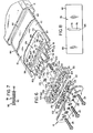
- an ink cartridge 10 in accordance with the invention, comprises an elongated hermetically sealed housing including a rectangular body 12 closed at one end by a cap 14.
- an ink container assembly comprised of an ink container 16 of a flexible, collapsible material which is mounted to an ink container support 18.
- the construction also includes a gasket support or retainer 20 between the ink container support 18 and cap 14.
- a cap sealing gasket 22 is provided between the cap 14 and gasket support 20 for purposes explained below.
- Fasteners 24 secure the ink container support 18 to the cap, with the gasket retainer 20 and the gasket 22 in place.
- the gasket retainer 20 has a base 21 and a peripheral wall 23 which projects from the base 21 and into engagement with the underside of the cap 14 when this assembly is fastened together. This fastened assembly is positioned within the housing body 12 and the cap 14 is secured, as by adhesive, to the body 12 to seal the cartridge.
- a path is provided for ink to flow from the interior of the ink container 16 to the exterior of the cartridge, from which the ink is delivered to an ink jet head of an ink jet printer.
- the cap 14 is provided with an ink flow port 26 which communicates through an O-ring portion 27 of gasket 22, when O-ring 27 is punctured, and through an ink flow passageway 28, described below, with the interior 29 of the ink container 16.
- a path is provided for delivering air from the ink jet printer to the cartridge. The air applies pressure to the exterior of the ink container 16 so as to enhance the flow of ink from the cartridge.
- the cap 14 includes an air flow port 32 which communicates through an O-ring portion 33 of gasket 22, when O-ring 33 is punctured, and through a pressurized air flow passageway 34, described below, with a portion 35 of the housing body 12 which is within the housing body and outside of the ink container 16.
- Typical operating pressures are approximately one pound per square inch. Because the housing is hermetically sealed, pressurized air is not lost from the housing. Also, ink does not leak from the housing in the unlikely event that the ink container 16 ruptures.
- the cartridge also includes an ink level sensor, designated generally at 38, for determining the level of ink within the cartridge.
- the ink level sensor includes a pair of electrical probes 40, 41 extending from the interior of the ink container 16 to the exterior of the cartridge housing. These probes are of an electrically conductive material which resists corrosion by the ink, such as stainless steel.
- the ink jet printer applies an alternating current voltage across the probes at a location outside of the housing.
- the resistance in a conducting path through the ink between the probes is monitored. This resistance varies as ink is used from the ink container and the ink container collapses. The magnitude of the resistance provides an indication of the amount of ink within the ink cartridge. In particular, from this resistance, a determination is made of when the ink cartridge is low of ink and should be changed.
- the housing body 12 is formed of a lightweight, durable, rigid, impact-resistant material.
- a polycarbonate material designated Lexan 141R-5107 and produced by General Electric Company. Because the cap 14 is exposed to ink passing through the ink flow port 27, it is desirable that this cap be formed of a material which resists corrosion when exposed to the ink. Polysulfone is one such suitable material.
- the body 12 is preferably molded and comprised of top and bottom plates 40, 44, first and second side plates 46, 48 and an end plate 50.
- a handle 52 is formed by portions of the top plate 44 and side plates 46, 48 which extend beyond the end plate 50. Thus, handle 52 extends transversely between the two side plates and provides a convenient grip for use when removing and replacing the cartridge.
- the plate 44 includes a raised central portion 54, while keys 56 project upwardly from the plate 4D. These keys and raised portion fit within a corresponding cartridge receiving socket of the ink jet printer and prevent inadvertant reversed installation of the cartridge.
- Guides 58 project from the sides 46, 48 of the housing 12 and fit within slots in the cartridge socket to support and properly align the ink cartridge when installed.
- the ink container assembly is best understood with reference to Figs. 3, 4 and 6.
- the ink container support 18 includes a support plate 70 with a flat planar ink container mounting surface 72 to which the ink container 16 is directly mounted and sealed. Although adhesive seals are suitable, in the preferred embodiment, this sealing is accomplished by thermally fusing the ink container to the mounting surface.
- a central opening 74 (Fig. 8) is provided in a rectangular sheet 76 of ink container forming material.
- the ink container support 18 is inserted upwardly through this opening 74 to position the marginal edge portions 78 of the sheet which bound the opening 74 against the mounting surface 72, as shown in Fig. 6. These edge portions are then thermally fused to the mounting surface.
- the ink container side forming portions 80, 82 of the sheet 76 are folded about the longitudinal axis of the ink container support plate 70, that is, along fold line 83 in Fig. 8, until positioned as shown in Fig. 6.
- the sides 80, 82 are then sealed together along edges 84, as by heat sealing, to complete the ink container assembly.
- the ink container support 18 is formed of a material which resists corrosion by the ink, with polyethylene being one suitable material.
- the ink container 16 see Fig. 7, is formed of a sheet 76 of multi-layered construction.
- the inner most layer 90 is comprised of a material which is compatible with the ink. That is, it resists corrosion by the ink. Also, this material is suitable for heat sealing.
- This first layer may comprise a low density polyethylene.
- the central layer 92 of sheet 76 provides a vapor barrier which minimizes the passage of gas into the ink container 16. Gas in the ink may form minute bubbles which clog the ink jet head of the printer.
- One suitable vapor barrier is a sandwich of a layer of polyvinylacetate between two layers of polyvinylidene chloride. This latter material is commonly designated by the trademark SARAN.
- the outer layer 93 is an ink container reinforcing material, which adds strength and some stiffness to the ink container.
- One suitable example is sixty guage biaxial nylon. A multi-layered material which fits this description is presently being sold by Champion International Corporation of San Leandro, California for applications such as containing wine within cardboard cartons.
- the stiffness of the outer layer facilitates the collapsing of the bag in a predictable manner. This factor improves the performance of the ink level sensor 38, as explained below. Moreover, with this construction, and due to the relatively greater stiffness of applicants container when compared to the known prior art, applicant is able to easily remove all gas from the ink container prior to filling the container with ink. This is accomplished by applying a vacuum to the ink flow port 32, which fully collapses the ink container and removes gas from the container.
- plural fastener receiving bosses 100 project in a first direction toward cap 14 from the surface of the ink container support plate 70.
- Each of the fasteners 24 pass through an opening in the cap, an O-ring portion 102 of the gasket 22, a projection or boss 104 extending in the first direction from the base 21 of the gasket retainer 20, and is threaded into the fastener receiving bosses 100.
- the ink container support 18 interfits the gasket retainer 20 so as to strengthen the construction. More specifically, the bosses 100 mate within corresponding recesses 106 which are provided in the gasket retainer base 21. Thus, when the cartridge is assembled, the ink container support is held securely in place.
- An annular ink flow passageway defining projection 110 also extends in the first direction toward cap 14 from the plate 70.
- the ink flow passageway 28 extends through projection 110.
- ink flow projection 110 passes through an opening 114 through the base 21 of the gasket retainer 20. This projection 110 abuts the interior surface of the gasket 0-ring portion 27.
- the opposite surface of the O-ring portion 27 surrounds and seals the ink flow port 26.
- the center 116 of the O-ring portion 27 is initially sealed as indicated in Fig. 3. When this seal is punctured, ink is permitted to flow from the ink container 16, through the ink flow passageway 28, through the gasket portion 27 and out of the ink flow port 26.
- a check valve assembly 120 is provided within the passageway 78.
- the assembly 120 includes a valve having a hemispherical head 122.
- the head 122 is urged against a valve seat 124 of the 0-ring portion 27 by a coil spring 126 positioned within the ink flow passageway.
- the valve has a stem 134 which extends loosely within the center of the coil spring so that the valve is retained in place without the need for adhesive.
- the valve and spring are preferably of an ink corrosion resistant material, such as respectively of polyethylene and stainless steel.
- a reinforcing rib 140 extends between the various projections of the ink container support. This rib has a notch 142 which is positioned in alignment with the pressure fluid port 32 when the cartridge is assembled.
- the notch 42 provides an enlarged unobstructed opening and clearance for insertion of an air supply needle into the interior 35 of the housing 12.
- gasket retaining projections extend in the first direction toward the cap 14 from the base 21 of the gasket retainer 20.
- these gasket retaining projections include the bosses 104.
- these projections include annular projections 150, 152 through which the respective probes 40, 41 are inserted when the cartridge is assembled.
- an annular pressure air flow projection 156 extends in this first direction from the base 21 of the gasket retainer 20.
- the air flow passageway 34 passes through the projection 156.
- the air flow projection extends into engagement with the interior surface of the O-ring portion 33 of the gasket 22.
- the other surface of O-ring portion 33 is positioned against the cap 14 and surrounds and seals the air flow port 32.
- the center 158 of O-ring portion 33 is initially sealed to block the flow of air through port 32 until the gasket is punctured.
- pressurized air may be delivered through the flow port 32, through the gasket O-ring portion 33, through the passageway 34, and past the notch 142 and into the interior 35 of the housing 12.
- Reinforcing ribs provide added support to the various projections from the gasket retainer.
- the gasket 22 is held by the projections of the gasket retainer 20 against the cap 14.
- Appropriate recesses, unnumbered, are provided in the interior surface of the cap 14 for receiving the gasket 22.
- the probes 40, 41 are preferably molded into the ink container support 18 during the manufacture of this support.
- Projections 168, 169 extend toward the cap 14 from the ink container plate 70 and surround and reinforce the respective probes 40, 41 at the location where the probes emerge from the plate 70.
- Probe 40 extends from the projection 168, through projection 150 of the gasket retainer 20, through an O-ring portion 170 of the gasket 22 and through an opening in cap 14 to the exterior of the cartridge.
- probe 41 extends from projection 169, through projection 152 of the gasket retainer 20, through a corresponding O-ring portion 170 of the gasket 22 and through another opening in cap 14 to the exterior of the cartridge.
- O-rings 172 surround and seal the probes 40, 41 at a location between projections 168, 169 and the base 21 of the gasket retainer 20.
- the probes 40, 41 are supported securely and are easily accessible for application of a voltage across the ends of the probes which are exposed to the exterior of the cartridge.
- the gaskets 22 and 172 are typically of an ink corrosion resistant material of suitable resiliency, such as rubber. Ethylenepropylene of 50 durometer on the Shore A scale is one suitable gasket material. Also, the gasket support 20 may be of the same material as housing 12.
- the ink cartridge 10 is extremely resistant to ink leakage arising from impact to the cartridge, environmental temperature fluctuations, above normal pressure within the ink cartridge, and due to exposure of internal and external portions of the cartridge housing to ink. Moreover, the ink cartridge is easy to manufacture, install and use.
- the ink level sensor 38 and its operation will be described with reference to Figs. 3, 4 and 5.
- the ink level sensor 38 includes a probe supporting structure 174 projecting from the ink container support plate 70 into the interior of the ink container 16. A portion of the probes, in this case the probe tips 188, 190 are exposed by the supporting structure to ink within the interior of the ink container 16.
- the ink being conductive, upon application of a voltage across the probes, the resistance of conductive path through the ink and between the two probes may be monitored by the ink jet printer. As ink is used, the ink container 16 collapses as shown in dashed lines in Figs. 4 and 5. Eventually, the path between the two probes through the ink is completely blocked by the collapsed ink container 16. When this occurs, the monitored resistance jumps to a high level. This change in resistance provides an indication that the ink cartridge 16 is low of ink and should be replaced.
- the probe supporting structure 174 may comprise a platform 174 supported by necks 180, 182 which project from the ink container support plate 70.
- the probes 40, 41 extend through the respective necks and into the interior of the platform 174.
- these necks are tapered moving away from the ink container support plate 70. This tapering guides the container 16 as it collapses to facilitate the container in a controlled uniform manner.
- Apertures 184, 186 are provided through the platform 174 with the tips 188, 190 of the probes extending into these apertures. Thus, the exposed portions of the probes are completely surrounded by the platform 174.
- the ink container 16 collapses against upper and lower flat planar ink container closure surfaces 176, 178 of platform 174. This closes off the conductive path between the two probes. Furthermore, this ink container collapses against surfaces 176, 178 when consistently the same amount of ink remains in the ink cartridge.
- the probes are sized so as not to project into the planes of the upper and lower surfaces 176, 178 of the platform. Therefore, the probes themselves do not interfere with the closing of the ink container against the closure surfaces.
- a flat closure surface is provided between the exposed regions of the probe. Only one such flat surface would be provided in the event the probes are only exposed to ink through one surface of the probe supporting structure.
- the cartridges may be changed before they run dry of ink, which could cause a bubble to form in the ink jet head and clog the head. For example, for a 200 milliliter volume cartridge, it is desirable to change the cartridge when no less than 20 milliliters of ink remain. Also, changing of the cartridges is not performed too soon, which would waste significant amounts of ink in the cartridge.
- the ink jet printer is provided with a shut off circuit which automatically stops the printer when a cartridge is low of ink, as indicated by the resistance measured across the probes. After the cartridge is replaced, the printer is then restarted.
Landscapes
- Ink Jet (AREA)
Applications Claiming Priority (2)
| Application Number | Priority Date | Filing Date | Title |
|---|---|---|---|
| US678907 | 1984-12-06 | ||
| US06/678,907 US4568954A (en) | 1984-12-06 | 1984-12-06 | Ink cartridge manufacturing method and apparatus |
Publications (2)
| Publication Number | Publication Date |
|---|---|
| EP0184456A2 true EP0184456A2 (de) | 1986-06-11 |
| EP0184456A3 EP0184456A3 (de) | 1987-01-07 |
Family
ID=24724796
Family Applications (1)
| Application Number | Title | Priority Date | Filing Date |
|---|---|---|---|
| EP85308866A Withdrawn EP0184456A3 (de) | 1984-12-06 | 1985-12-05 | Gerät und Verfahren zur Herstellung von Tintenkassetten |
Country Status (4)
| Country | Link |
|---|---|
| US (1) | US4568954A (de) |
| EP (1) | EP0184456A3 (de) |
| JP (1) | JPS61148063A (de) |
| CA (1) | CA1238240A (de) |
Cited By (1)
| Publication number | Priority date | Publication date | Assignee | Title |
|---|---|---|---|---|
| US7185975B2 (en) | 2003-03-11 | 2007-03-06 | Brother Kogyo Kabushiki Kaisha | Ink detecting apparatus and ink package |
Families Citing this family (80)
| Publication number | Priority date | Publication date | Assignee | Title |
|---|---|---|---|---|
| JP2558103B2 (ja) * | 1986-07-31 | 1996-11-27 | キヤノン株式会社 | インク供給装置 |
| USD338912S (en) | 1991-04-03 | 1993-08-31 | Canon Kabushiki Kaisha | Ink cartridge for printer |
| US5406320A (en) * | 1992-03-10 | 1995-04-11 | Scitex Digital Printing, Inc. | Ink replenishment assemblies for ink jet printers |
| US5464578A (en) * | 1992-03-18 | 1995-11-07 | Hewlett-Packard Company | Method of making a compact fluid coupler for thermal inkjet print cartridge ink reservoir |
| USD348477S (en) | 1992-12-01 | 1994-07-05 | Canon Kabushiki Kaisha | Ink cartridge for printer |
| USD348478S (en) | 1992-12-01 | 1994-07-05 | Canon Kabushiki Kaisha | Ink cartridge for printer |
| US5825387A (en) * | 1995-04-27 | 1998-10-20 | Hewlett-Packard Company | Ink supply for an ink-jet printer |
| US6203147B1 (en) * | 1994-12-22 | 2001-03-20 | Hewlett-Packard Company | Electrical and fluidic interface for an ink supply |
| US5956057A (en) * | 1996-08-30 | 1999-09-21 | Hewlett-Packard Company | Ink container having electronic and mechanical features enabling plug compatibility between multiple supply sizes |
| US6142617A (en) * | 1995-04-27 | 2000-11-07 | Hewlett-Packard Company | Ink container configured for use with compact supply station |
| US7114801B2 (en) * | 1995-04-27 | 2006-10-03 | Hewlett-Packard Development Company, L.P. | Method and apparatus for providing ink to an ink jet printing system |
| US6322207B1 (en) | 1995-04-27 | 2001-11-27 | Hewlett-Packard Company | Replaceable pump module for receiving replaceable ink supplies to provide ink to an ink jet printing system |
| US6183077B1 (en) | 1995-04-27 | 2001-02-06 | Hewlett-Packard Company | Method and apparatus for keying ink supply containers |
| US7008050B2 (en) * | 1995-04-27 | 2006-03-07 | Hewlett-Packard Development Company, L.P. | Ink container refurbishment system |
| US6017118A (en) | 1995-04-27 | 2000-01-25 | Hewlett-Packard Company | High performance ink container with efficient construction |
| US5900896A (en) * | 1995-04-27 | 1999-05-04 | Hewlett-Packard Company | Ink cartridge adapters |
| US7249831B2 (en) * | 1995-04-27 | 2007-07-31 | Hewlett-Packard Development Company, L.P. | Ink container refurbishment system |
| US6074050A (en) | 1997-12-03 | 2000-06-13 | Hewlett-Packard Company | Method and apparatus for venting an ink container |
| US5856839A (en) * | 1995-04-27 | 1999-01-05 | Hewlett-Packard Company | Ink supply having an integral pump |
| US5900895A (en) | 1995-12-04 | 1999-05-04 | Hewlett-Packard Company | Method for refilling an ink supply for an ink-jet printer |
| USD416573S (en) | 1996-06-05 | 1999-11-16 | Hewlett-Packard Company | Fluid container |
| US5815182A (en) | 1995-12-04 | 1998-09-29 | Hewlett-Packard Company | Fluid interconnect for ink-jet pen |
| USD438899S1 (en) | 1995-12-04 | 2001-03-13 | Hewlett-Packard Company | Fluid container |
| USD425553S (en) * | 1998-04-09 | 2000-05-23 | Hewlett-Packard Company | Fluid container |
| US5847734A (en) | 1995-12-04 | 1998-12-08 | Pawlowski, Jr.; Norman E. | Air purge system for an ink-jet printer |
| US5771053A (en) | 1995-12-04 | 1998-06-23 | Hewlett-Packard Company | Assembly for controlling ink release from a container |
| USD437610S1 (en) | 1995-12-04 | 2001-02-13 | Hewlett-Packard Company | Fluid container |
| US5732751A (en) | 1995-12-04 | 1998-03-31 | Hewlett-Packard Company | Filling ink supply containers |
| USD444497S1 (en) | 1995-12-04 | 2001-07-03 | Hewlett-Packard Company | Fluid container |
| EP0778148B1 (de) * | 1995-12-04 | 2001-12-05 | Hewlett-Packard Company, A Delaware Corporation | Kodierungsvorrichtung für Tintenzufuhrbehälter |
| US6164743A (en) * | 1996-04-17 | 2000-12-26 | Hewlett-Packard Company | Ink container with an inductive ink level sense |
| US6074042A (en) * | 1997-06-04 | 2000-06-13 | Hewlett-Packard Company | Ink container having a guide feature for insuring reliable fluid, air and electrical connections to a printing system |
| US6030074A (en) * | 1996-07-15 | 2000-02-29 | Hewlett-Packard Company | Method and apparatus for delivering pressurized ink to a printhead |
| USD391986S (en) | 1996-10-29 | 1998-03-10 | Hewlett-Packard Company | Fluid container |
| WO1998025817A1 (en) * | 1996-12-09 | 1998-06-18 | Cartercopters, L.L.C. | Fuselage door for pressurized aircraft |
| US5788388A (en) * | 1997-01-21 | 1998-08-04 | Hewlett-Packard Company | Ink jet cartridge with ink level detection |
| US7188918B2 (en) * | 1997-01-21 | 2007-03-13 | Hewlett-Packard Development Company, L.P. | Ink delivery system adapter |
| US6322205B1 (en) | 1997-01-21 | 2001-11-27 | Hewlett-Packard Company | Ink delivery system adapter |
| US5860363A (en) * | 1997-01-21 | 1999-01-19 | Hewlett-Packard Company | Ink jet cartridge with separately replaceable ink reservoir |
| US6168262B1 (en) | 1997-01-30 | 2001-01-02 | Hewlett-Packard Company | Electrical interconnect for replaceable ink containers |
| CA2234353A1 (en) * | 1997-04-11 | 1998-10-11 | David C. Kamp | Liquid containment and dispensing device with improved attachment of liquid containing pouch to chassis |
| US5917526A (en) * | 1997-04-23 | 1999-06-29 | Hewlett-Packard Company | Method and apparatus for ink container locking |
| US6585359B1 (en) | 1997-06-04 | 2003-07-01 | Hewlett-Packard Development Company, L.P. | Ink container providing pressurized ink with ink level sensor |
| US6151039A (en) * | 1997-06-04 | 2000-11-21 | Hewlett-Packard Company | Ink level estimation using drop count and ink level sense |
| US6010210A (en) | 1997-06-04 | 2000-01-04 | Hewlett-Packard Company | Ink container having a multiple function chassis |
| US5992975A (en) * | 1997-06-04 | 1999-11-30 | Hewlett-Packard Company | Electrical interconnect for an ink container |
| ES2257508T3 (es) * | 1997-06-04 | 2006-08-01 | Hewlett-Packard Company | Adaptador para sistema de entrega de tinta. |
| US5949459A (en) | 1997-06-04 | 1999-09-07 | Hewlett-Packard Company | Method and apparatus for securing an ink container |
| US6158853A (en) * | 1997-06-05 | 2000-12-12 | Hewlett-Packard Company | Ink containment system including a plural-walled bag formed of inner and outer film layers |
| US6068371A (en) * | 1997-09-22 | 2000-05-30 | Owens-Illinois Closure Inc. | Liquid containment and dispensing device with improved position indicating indicia |
| USD411568S (en) | 1997-10-14 | 1999-06-29 | Hewlett-Packard Company | Fluid container |
| US6145967A (en) * | 1997-10-24 | 2000-11-14 | Hewlett-Packard Company | Method and apparatus for configuring a fluid interconnect for an ink-jet printhead |
| JP4210034B2 (ja) * | 1998-03-04 | 2009-01-14 | ヒューレット・パッカード・カンパニー | インク容器を一新するシステム |
| US6116723A (en) * | 1998-03-09 | 2000-09-12 | Hewlett-Packard | Low cost pressurizable ink container |
| USD425554S (en) * | 1998-04-09 | 2000-05-23 | Hewlett-Packard Company | Ink container |
| USD422306S (en) * | 1998-04-09 | 2000-04-04 | Hewlett-Packard Company | End cap for an ink container |
| USD432567S (en) * | 1998-04-09 | 2000-10-24 | Hewlett-Packard Company | Fluid container |
| US6183072B1 (en) | 1998-04-29 | 2001-02-06 | Hewlett-Packard Company | Seal using gasket compressed normal to assembly axis of two parts |
| USD415790S (en) * | 1998-05-22 | 1999-10-26 | Hewlett-Packard Company | Fluid container |
| USD428438S (en) * | 1999-02-03 | 2000-07-18 | Hewlett-Packard Company | Fluid container cap |
| USD428437S (en) * | 1999-02-03 | 2000-07-18 | Hewlett-Packard Company | Fluid container |
| USD428915S (en) * | 1999-02-03 | 2000-08-01 | Hewlett-Packard Company | Fluid container cap |
| JP2001063090A (ja) | 1999-04-27 | 2001-03-13 | Canon Inc | インクタンク、該インクタンクに用いられる弁ユニット、前記インクタンクの製造方法、前記インクタンクを備えたインクジェットヘッドカートリッジおよびインクジェット記録装置 |
| JP2001071522A (ja) * | 1999-09-03 | 2001-03-21 | Canon Inc | 液体容器およびプリント装置 |
| EP1849608B1 (de) | 2000-01-21 | 2010-04-21 | Seiko Epson Corporation | Tintenpatrone und Tintenstrahldruckvorrichtung mit einer derartigen Tintenpatrone |
| ES2386656T3 (es) * | 2000-01-21 | 2012-08-24 | Seiko Epson Corporation | Cartucho de tinta para uso en aparato de registro y aparato de registro de inyección de tinta |
| US6786584B2 (en) * | 2001-10-09 | 2004-09-07 | Brother Kogyo Kabushiki Kaisha | Ink housing device reliably preventing ink leakage |
| US7147310B2 (en) * | 2002-01-30 | 2006-12-12 | Hewlett-Packard Development Company, L.P. | Printing-fluid container |
| FR2843443B1 (fr) * | 2002-08-08 | 2004-11-26 | Valeo Vision | Procede de realisation d'un dispositif d'eclairage ou de signalisation, et dispositif d'eclairage ou de signalisation obtenu par ce procede |
| JP4292832B2 (ja) * | 2003-03-11 | 2009-07-08 | ブラザー工業株式会社 | インクパッケージ |
| US7029082B2 (en) | 2003-07-02 | 2006-04-18 | Hewlett-Packard Development Company, L.P. | Printing device having a printing fluid detector |
| JP2007090736A (ja) * | 2005-09-29 | 2007-04-12 | Brother Ind Ltd | インクカートリッジ |
| US7284848B2 (en) * | 2005-11-28 | 2007-10-23 | Brother Kogyo Kabushiki Kaisha | Ink cartridges |
| JP2007152861A (ja) | 2005-12-08 | 2007-06-21 | Olympus Corp | 画像記録装置が備えるインク検出装置、インク検出方法、及びプログラム |
| WO2010056541A1 (en) * | 2008-10-29 | 2010-05-20 | 3M Innovative Properties Company | Electron beam cured silicone materials |
| US8057011B2 (en) * | 2009-05-26 | 2011-11-15 | Hewlett-Packard Development Company, L.P. | Fluid dispensing device |
| US20110279497A1 (en) * | 2010-05-17 | 2011-11-17 | Silverbrook Research Pty Ltd | Method of priming and de-priming printhead |
| JP5842616B2 (ja) * | 2012-01-05 | 2016-01-13 | 株式会社リコー | 液体カートリッジ、画像形成装置 |
| US8733910B1 (en) * | 2013-01-30 | 2014-05-27 | Hewlett-Packard Development Company, L.P. | Unitary multiple seal mechanism |
| WO2017014779A1 (en) * | 2015-07-22 | 2017-01-26 | Hewlett-Packard Development Company, L.P. | Printing fluid container |
Family Cites Families (7)
| Publication number | Priority date | Publication date | Assignee | Title |
|---|---|---|---|---|
| JPS5641148A (en) * | 1979-09-12 | 1981-04-17 | Canon Kk | Vessel for recording liquid |
| US4386929A (en) * | 1980-01-18 | 1983-06-07 | Alza Corporation | Elastomeric bladder assembly |
| US4387833A (en) * | 1980-12-16 | 1983-06-14 | Container Industries, Inc. | Apparatus for containing and dispensing fluids under pressure and method of producing same |
| JPS57201682A (en) * | 1981-06-08 | 1982-12-10 | Canon Inc | Ink cassette |
| DE3238063A1 (de) * | 1982-10-14 | 1984-04-19 | Olympia Werke Ag, 2940 Wilhelmshaven | Wechselbehaelter mit einer tintenvorratskammer fuer ein tintenschreibwerk |
| JPS59131837U (ja) * | 1983-02-23 | 1984-09-04 | シャープ株式会社 | インクジエツトプリンタのインクカ−トリツジ装置 |
| JPS59214656A (ja) * | 1983-05-19 | 1984-12-04 | Sanyo Electric Co Ltd | インクジエツトプリンタ |
-
1984
- 1984-12-06 US US06/678,907 patent/US4568954A/en not_active Expired - Fee Related
-
1985
- 1985-11-29 CA CA000496561A patent/CA1238240A/en not_active Expired
- 1985-12-05 JP JP60274272A patent/JPS61148063A/ja active Granted
- 1985-12-05 EP EP85308866A patent/EP0184456A3/de not_active Withdrawn
Cited By (1)
| Publication number | Priority date | Publication date | Assignee | Title |
|---|---|---|---|---|
| US7185975B2 (en) | 2003-03-11 | 2007-03-06 | Brother Kogyo Kabushiki Kaisha | Ink detecting apparatus and ink package |
Also Published As
| Publication number | Publication date |
|---|---|
| CA1238240A (en) | 1988-06-21 |
| US4568954A (en) | 1986-02-04 |
| JPH0355313B2 (de) | 1991-08-22 |
| JPS61148063A (ja) | 1986-07-05 |
| EP0184456A3 (de) | 1987-01-07 |
Similar Documents
| Publication | Publication Date | Title |
|---|---|---|
| US4568954A (en) | Ink cartridge manufacturing method and apparatus | |
| US4551734A (en) | Ink cartridge with ink level sensor | |
| EP1457342B1 (de) | Behältnis und Ausgabevorrichtung für Flüssigkeit | |
| US5126767A (en) | Ink tank with dual-member sealing closure | |
| US6364472B1 (en) | Method and apparatus for keying ink supply containers | |
| KR100521961B1 (ko) | 오프 캐리지 잉크 용기 및 잉크 용기의 조립 방법 | |
| US6053607A (en) | Negative pressure ink delivery system | |
| EP0903236B1 (de) | Flüssigkeitsbehälter und Abgabevorrichtung | |
| US6276788B1 (en) | Ink cartridge for an ink jet printer having quick disconnect valve 09 | |
| US6341853B1 (en) | Continuous refill of spring bag reservoir in an ink-jet swath printer/plotter | |
| US6010210A (en) | Ink container having a multiple function chassis | |
| EP2002981B1 (de) | Verfahren zur Herstellung eines Flüssigkeitsbehälters | |
| EP0712727A2 (de) | Tintenzufuhrvorrichtung für einer Tintenstrahldrucker und Tintenbehälter dafür | |
| KR20010013318A (ko) | 잉크 용기 및 잉크 용기를 잉크젯 인쇄 시스템내에설치하기 위한 조립 방법 | |
| US6676251B1 (en) | Liquid containment and dispensing device with improved resistance to shock loads | |
| US6692117B1 (en) | Liquid containment and dispensing device with improved flow control valve | |
| EP0870618A2 (de) | Behältnis und Ausgabevorrichtung für Flüssigkeit | |
| JPS61116548A (ja) | 記録液カ−トリツジ |
Legal Events
| Date | Code | Title | Description |
|---|---|---|---|
| PUAI | Public reference made under article 153(3) epc to a published international application that has entered the european phase |
Free format text: ORIGINAL CODE: 0009012 |
|
| AK | Designated contracting states |
Kind code of ref document: A2 Designated state(s): DE FR GB NL |
|
| PUAL | Search report despatched |
Free format text: ORIGINAL CODE: 0009013 |
|
| AK | Designated contracting states |
Kind code of ref document: A3 Designated state(s): DE FR GB NL |
|
| 17P | Request for examination filed |
Effective date: 19870609 |
|
| 17Q | First examination report despatched |
Effective date: 19890310 |
|
| STAA | Information on the status of an ep patent application or granted ep patent |
Free format text: STATUS: THE APPLICATION IS DEEMED TO BE WITHDRAWN |
|
| 18D | Application deemed to be withdrawn |
Effective date: 19900403 |
|
| RIN1 | Information on inventor provided before grant (corrected) |
Inventor name: ROSBACK, MARTIN D. |