EP0184491A1 - Wassererhitzer - Google Patents
Wassererhitzer Download PDFInfo
- Publication number
- EP0184491A1 EP0184491A1 EP85402232A EP85402232A EP0184491A1 EP 0184491 A1 EP0184491 A1 EP 0184491A1 EP 85402232 A EP85402232 A EP 85402232A EP 85402232 A EP85402232 A EP 85402232A EP 0184491 A1 EP0184491 A1 EP 0184491A1
- Authority
- EP
- European Patent Office
- Prior art keywords
- tank
- wall
- hollow body
- molded
- reservoir
- Prior art date
- Legal status (The legal status is an assumption and is not a legal conclusion. Google has not performed a legal analysis and makes no representation as to the accuracy of the status listed.)
- Withdrawn
Links
- XLYOFNOQVPJJNP-UHFFFAOYSA-N water Substances O XLYOFNOQVPJJNP-UHFFFAOYSA-N 0.000 title claims abstract description 32
- 238000010438 heat treatment Methods 0.000 claims abstract description 40
- 239000000463 material Substances 0.000 claims abstract description 15
- 229910000838 Al alloy Inorganic materials 0.000 claims description 6
- 239000003989 dielectric material Substances 0.000 claims description 5
- 238000003466 welding Methods 0.000 claims description 5
- 239000011248 coating agent Substances 0.000 claims description 4
- 238000000576 coating method Methods 0.000 claims description 4
- 238000000465 moulding Methods 0.000 claims description 4
- 230000001681 protective effect Effects 0.000 claims description 3
- 239000004959 Rilsan Substances 0.000 claims description 2
- 239000004809 Teflon Substances 0.000 claims description 2
- 229920006362 Teflon® Polymers 0.000 claims description 2
- 238000002788 crimping Methods 0.000 claims description 2
- 239000004033 plastic Substances 0.000 claims description 2
- 229920003023 plastic Polymers 0.000 claims description 2
- 229920000915 polyvinyl chloride Polymers 0.000 claims description 2
- 239000004800 polyvinyl chloride Substances 0.000 claims description 2
- 229910052751 metal Inorganic materials 0.000 abstract description 8
- 239000002184 metal Substances 0.000 abstract description 8
- 238000004519 manufacturing process Methods 0.000 description 9
- 230000007797 corrosion Effects 0.000 description 8
- 238000005260 corrosion Methods 0.000 description 8
- 239000007788 liquid Substances 0.000 description 3
- 238000005259 measurement Methods 0.000 description 2
- 238000003303 reheating Methods 0.000 description 2
- 239000000126 substance Substances 0.000 description 2
- 208000031968 Cadaver Diseases 0.000 description 1
- 241001415961 Gaviidae Species 0.000 description 1
- 229910000831 Steel Inorganic materials 0.000 description 1
- MKPXGEVFQSIKGE-UHFFFAOYSA-N [Mg].[Si] Chemical compound [Mg].[Si] MKPXGEVFQSIKGE-UHFFFAOYSA-N 0.000 description 1
- 238000009825 accumulation Methods 0.000 description 1
- 239000002253 acid Substances 0.000 description 1
- 230000015572 biosynthetic process Effects 0.000 description 1
- 230000000295 complement effect Effects 0.000 description 1
- 239000002131 composite material Substances 0.000 description 1
- 239000004020 conductor Substances 0.000 description 1
- 238000010276 construction Methods 0.000 description 1
- 238000001816 cooling Methods 0.000 description 1
- 230000007547 defect Effects 0.000 description 1
- 238000001514 detection method Methods 0.000 description 1
- 230000005611 electricity Effects 0.000 description 1
- 238000007654 immersion Methods 0.000 description 1
- 239000010954 inorganic particle Substances 0.000 description 1
- 238000003754 machining Methods 0.000 description 1
- 239000007769 metal material Substances 0.000 description 1
- 238000012986 modification Methods 0.000 description 1
- 230000004048 modification Effects 0.000 description 1
- 239000011146 organic particle Substances 0.000 description 1
- 230000001105 regulatory effect Effects 0.000 description 1
- 230000000717 retained effect Effects 0.000 description 1
- 239000000523 sample Substances 0.000 description 1
- 238000000926 separation method Methods 0.000 description 1
- 239000010959 steel Substances 0.000 description 1
- 238000010301 surface-oxidation reaction Methods 0.000 description 1
- 229920002994 synthetic fiber Polymers 0.000 description 1
Images


Classifications
-
- F—MECHANICAL ENGINEERING; LIGHTING; HEATING; WEAPONS; BLASTING
- F24—HEATING; RANGES; VENTILATING
- F24H—FLUID HEATERS, e.g. WATER OR AIR HEATERS, HAVING HEAT-GENERATING MEANS, e.g. HEAT PUMPS, IN GENERAL
- F24H1/00—Water heaters, e.g. boilers, continuous-flow heaters or water-storage heaters
- F24H1/18—Water-storage heaters
- F24H1/181—Construction of the tank
-
- F—MECHANICAL ENGINEERING; LIGHTING; HEATING; WEAPONS; BLASTING
- F24—HEATING; RANGES; VENTILATING
- F24H—FLUID HEATERS, e.g. WATER OR AIR HEATERS, HAVING HEAT-GENERATING MEANS, e.g. HEAT PUMPS, IN GENERAL
- F24H1/00—Water heaters, e.g. boilers, continuous-flow heaters or water-storage heaters
- F24H1/18—Water-storage heaters
- F24H1/185—Water-storage heaters using electric energy supply
-
- F—MECHANICAL ENGINEERING; LIGHTING; HEATING; WEAPONS; BLASTING
- F24—HEATING; RANGES; VENTILATING
- F24H—FLUID HEATERS, e.g. WATER OR AIR HEATERS, HAVING HEAT-GENERATING MEANS, e.g. HEAT PUMPS, IN GENERAL
- F24H9/00—Details
- F24H9/12—Arrangements for connecting heaters to circulation pipes
- F24H9/13—Arrangements for connecting heaters to circulation pipes for water heaters
-
- F—MECHANICAL ENGINEERING; LIGHTING; HEATING; WEAPONS; BLASTING
- F24—HEATING; RANGES; VENTILATING
- F24H—FLUID HEATERS, e.g. WATER OR AIR HEATERS, HAVING HEAT-GENERATING MEANS, e.g. HEAT PUMPS, IN GENERAL
- F24H9/00—Details
- F24H9/18—Arrangement or mounting of grates or heating means
- F24H9/1809—Arrangement or mounting of grates or heating means for water heaters
- F24H9/1818—Arrangement or mounting of electric heating means
Definitions
- the present invention generally relates to apparatus for producing hot water and essentially relates to a device for producing hot water, in particular of the household type for domestic use, such as a water heater, distributor or bath heater for the supply of 'hot water.
- heating balloons for example closed under pressure with or without accumulation, comprising either a heat-insulated tank, or a tank not or only slightly thermally insulated and a body of heater in which energy, notably chemical or electrical energy, is transformed into heat transmitted to the liquid to be heated.
- the reservoir usually in the form of a cylindrical-spherical shell, is generally made of steel and comprises a cylindrical ferrule made of rolled sheet metal, joined welded, and assembled by welding at its ends respectively to two curved ends of pressed or repelled sheet metal to which welds are welded. of piping.
- the heat generator or heating element is generally constituted by electrical resistors forming either immersion heater, that is to say immersed in water of the reservoir so as to be in permanent direct physical contact therewith, ie barrel element mounted in an attached thermally conductive sheath, projecting inside the reservoir.
- thermal control instruments such as a thermometer, thermostat or the like also immerse either directly in the water by their thermosensitive part forming a probe, or in an attached thermally conductive sheath projecting inside the tank.
- the presence of roughness on the inner wall surface entails a risk of catching and retaining inorganic and organic particles coming from sanitary water.
- the object of the present invention is to eliminate the aforementioned drawbacks by providing a device for producing hot water which is simple in construction and structure, which is quick and economical to manufacture, and which is low and easy to maintain.
- the solution proposed by the present invention consists of a device for producing hot water of the type comprising a hollow body tank comprising pipe connection pipes and a heating body, characterized in that said hollow body is produced at least partially in a particularly metallic material capable of being molded, preferably in a shell or under pressure with its wall bushings and possibly remains raw in the finished state.
- the material capable of being molded above has good heat-conducting properties, and is preferably capable of being surface oxidized during molding to form a protective skin.
- Such a material is for example a foundry aluminum alloy.
- the heating body is constituted by a block made of a thermally conductive material preferably similar or identical to that of the aforementioned hollow body in which the heating element such as electrical resistance is embedded and which is removably attached. and fixed in direct heat-conducting contact to the external wall of said hollow body.
- the heating element is preferably housed removably in a blind cavity of the wall of the reservoir projecting towards the interior thereof.
- the water is heated indirectly by conduction and / or convection through the wall of the tank and the fact that the heating element is completely isolated or separated from any direct physical contact. with water, eliminates corrosion and clogging phenomena, and therefore any risk of failure for these causes.
- the heating element is molded into the mass of the tank, either in a concentrated manner at a local location, or in a manner distributed at several points on the wall of the tank. This allows heating reheating by stage particularly useful in case of need to use only a fraction of the water capacity of the tank.
- each aforementioned wall crossing is mounted, for example removably, a tube made of a dielectric material and which is fixed to said wall crossing by elements of dielectric material. This avoids any risk of electrolytic corrosion between the different parts present in the tank.
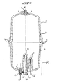
- the device for producing hot water comprises a reservoir with a hollow body 1 and a heating body 7.
- the reservoir is a hollow body of any suitable shape, in particular of revolution, entirely molded with its pipes or wall crossings 4, 4 ′ intended for the connection of the pipes.
- the reservoir is made of an aluminum alloy, in particular foundry, for example silicon-magnesium such as that whose standard conventional chemical designation is represented by the symbol AS10G.
- the tank 1 can be of any capacity varying for example between 1 and 300 liters.
- the reservoir 1 is molded either in two parts 2, 3 to be assembled later in a leaktight manner, or in a single piece if possible, and it possibly remains unmolded, due to the excellent surface condition plain or smooth thus obtained.
- the two parts 2, 3 respectively constitute two equal or unequal tank fractions and each of them is, in the example shown, bordered, at the level of the junction or separation plane, by an annular flange 13 radially projecting towards the outside.
- the assembly of parts 2 and 3 is carried out either by bolting or by a quick fixing device on flanges with possible interposition of a seal gasket, or by welding of the two flanges.
- the reservoir 1 is provided with at least two wall crossings 4 ′ and 4 made of material, respectively of cold water inlet 14 ′ and hot water outlet 14, preferably made in its domed bottoms.
- Each wall passage 4, 4 ′ is intended to receive, removably mounted, a tube 5, 5 ′ preferably made of a synthetic material such as in particular polyvinyl chloride.
- the pipes 5, 5 ' are advantageously fixed to the wall bushings 4, 4' by means of elements 6, 6 'such as bolts, nuts, screws or similar fixing members, preferably made of the same dielectric material.
- the heating body 7 is advantageously independent of the tank and attached removably thereon. This arrangement allows, unlike known devices, interchangeability of the heating body, facilitating repair or replacement thereof.
- the heating body 7 is constituted by a metal block 8, made of aluminum alloy in the example shown.
- this block can be made of any suitable material, preferably with properties similar to those of the material of the hollow body 1, that is to say having good thermal conductive properties.
- a heating element such as an electrical resistor, is embedded in the block 8 which is detachably fixed against the wall surface, in particular the outer wall of the reservoir, in direct heat-conducting contact with the latter.
- Such a fixing of the heating body to the tank is carried out for example by central tightening, in particular by nut on a screw inserted in the body 7.
- FIGs 3A and 3B show an alternative embodiment of the fixing of the heating body 7, which uses the cold water inlet 14 '.
- This arrangement allows the use of two strictly identical parts 2 and 3, hence a further improved manufacture of the tank.
- the heating body 7 is shaped so that it can be dismantled without dismantling the piping.
- a one-sided recess 21 allows the release of the heating body, after removing the nut 22 by sliding normal to the pipe 5 '.
- the heating body 7 comes to fit in an orifice present in the wall of the tank 1, and obtained in particular during molding.
- the heating body 7 then forms part of the inner wall of the tank body 1.
- a stirrup 24 bearing on the tank 1 is tightened against the latter by means of a nut 23 which, by screwing onto a threaded rod 25 integral with the heating body 7, allows a movement of the latter in the opposite direction to the movement of the stirrup 24, thereby fixing the heating body 7 to the wall of the tank at a predetermined location.
- the orifice made in the wall of the tank is of conical shape flaring towards the inside of the tank, so as to cooperate in leaktight manner with the heating body 7 shaped to form a waterproof complementary part of said orifice.
- the heating body 7 consists of an envelope or a closed enclosure 15 filled with a heat-transfer liquid such as water, at least partially surrounding the tank and in thermally conductive contact with that -this (see Figure 1).
- a heat-transfer liquid such as water
- thermometer thermometer, thermostat etc.
- the thermal measurement and regulation instruments are mounted externally on the tank and, like the heating elements, do not enter the volume containing the water thereof, measurement, detection and capture taking place indirectly.
- the wall of the reservoir 1 forms at least one inva thermowell protruding inwards and surrounded by water, thus constituting a cavity open towards the exterior 10.
- the blind cavity 10 is intended to preferably accommodate removably the heating element 7, for example in the form of barrel, which bathes in the air contained in the aforementioned cavity.
- Other similar cavities such as 12 are used to house the aforementioned measuring and regulating instruments.
- the reservoir 1 may optionally include an internal coating, in particular of plastic material such as that known commercially under the name of Rilsan or Teflon, to optionally perfect the protective oxide layer forming the skin of the metal. This coating is applied during the cooling of the molded part when it has reached the temperature suitable for the application of this coating.
- the device for producing hot water may include other modifications, without departing from the scope of the present invention.
- a material having good heat-conducting properties only for the production of the portion of the tank 1 comprising the heating body 7, the remaining portion may be made of composite material for example.
- the perfect internal smooth surface prevents any risk that retains foreign matter and corrosion, especially at assembly joints.
- the heating body is constituted by a heating element, such as one or more electrical resistances directly molded in the mass of the tank 1.
- FIGS. 5B and 5C show the case of molded resistors (26, 27) concentrated in a local location, preferably close to the cold water inlet pipe 14 '.
- the aforementioned resistors are molded in a locally thicker wall portion and projecting either inwardly (27) or outwardly (26) of the reservoir 1.
- resistors 28 are molded into the mass of the reservoir at points spaced from the wall of the latter.
- the resistors 28 are arranged opposite one another, thereby allowing the water contained in the tank to be heated in stages.
- these resistors allow the implementation of a fraction of the heating power adapted to the needs.
- These resistors also allow reheating of stages, by fractional heating or selective section of the tank height. We can also adapt to declining electricity prices.
- the barrel resistance is shaped to occupy the entire space of the cavity 10.
- the resistance is fixed by a metal bar fixed on the one hand to the resistance and on the other hand to the pipe 5 '.
Landscapes
- Engineering & Computer Science (AREA)
- Physics & Mathematics (AREA)
- Thermal Sciences (AREA)
- Chemical & Material Sciences (AREA)
- Combustion & Propulsion (AREA)
- Mechanical Engineering (AREA)
- General Engineering & Computer Science (AREA)
- Resistance Heating (AREA)
- Heat-Pump Type And Storage Water Heaters (AREA)
Applications Claiming Priority (2)
| Application Number | Priority Date | Filing Date | Title |
|---|---|---|---|
| FR8417678 | 1984-11-20 | ||
| FR8417678A FR2573519B1 (fr) | 1984-11-20 | 1984-11-20 | Dispositif de production d'eau chaude |
Publications (1)
| Publication Number | Publication Date |
|---|---|
| EP0184491A1 true EP0184491A1 (de) | 1986-06-11 |
Family
ID=9309769
Family Applications (1)
| Application Number | Title | Priority Date | Filing Date |
|---|---|---|---|
| EP85402232A Withdrawn EP0184491A1 (de) | 1984-11-20 | 1985-11-18 | Wassererhitzer |
Country Status (4)
| Country | Link |
|---|---|
| EP (1) | EP0184491A1 (de) |
| ES (1) | ES8703610A1 (de) |
| FR (1) | FR2573519B1 (de) |
| PT (1) | PT81518B (de) |
Cited By (7)
| Publication number | Priority date | Publication date | Assignee | Title |
|---|---|---|---|---|
| EP0337357A3 (en) * | 1988-04-11 | 1990-10-10 | State Industries, Inc. | Tank construction and method of manufacture |
| FR2774454A1 (fr) | 1998-02-02 | 1999-08-06 | Inst Francais Du Petrole | Dispositif d'auto-combustion de dechets heterogenes et/ou graisseux et appareil de production d'eau chaude associe |
| RU2193146C2 (ru) * | 1997-12-29 | 2002-11-20 | Мерлони Термосанитари С.П.А. | Водонагреватель, выполненный из стойкой к давлению пластмассы |
| WO2004044499A1 (en) * | 2002-11-13 | 2004-05-27 | Cadif Srl | Water heater with an external electric winding |
| EP1519122A1 (de) * | 2003-09-26 | 2005-03-30 | J. Eberspächer GmbH & Co. KG | Wärmetauscheranordnung für ein Heizgerät, insbesondere Fahrzeugheizgerät |
| GB2454952A (en) * | 2007-11-21 | 2009-05-27 | David Luke Pringle | Aluminium hot water cylinder with internal piston-like baffle |
| WO2010097566A1 (en) * | 2009-02-24 | 2010-09-02 | David Luke Pringle | Improved fluid container |
Families Citing this family (1)
| Publication number | Priority date | Publication date | Assignee | Title |
|---|---|---|---|---|
| WO2018021959A1 (en) * | 2016-07-27 | 2018-02-01 | Chew Sin Khow | Heating apparatus |
Citations (5)
| Publication number | Priority date | Publication date | Assignee | Title |
|---|---|---|---|---|
| GB138816A (en) * | 1919-05-02 | 1920-02-19 | Oliver John Wootton | Improvements in or relating to hollow-ware |
| US2861169A (en) * | 1956-06-08 | 1958-11-18 | Handling Equipment Mfg Corp | Electric water heater |
| DE1147368B (de) * | 1960-08-12 | 1963-04-18 | Alfred Eckerfeld | Warmwasserbereiter mit glockenfoermigem Behaelter |
| DE1600606A1 (de) * | 1967-06-02 | 1970-03-05 | Werner Schaffer Elektro Akusti | Gefaess fuer Inkrustationen bildende Fluessigkeiten |
| GB1246476A (en) * | 1968-09-03 | 1971-09-15 | Santon Ltd | Water heating and/or storage tanks comprising domed components |
-
1984
- 1984-11-20 FR FR8417678A patent/FR2573519B1/fr not_active Expired
-
1985
- 1985-11-18 EP EP85402232A patent/EP0184491A1/de not_active Withdrawn
- 1985-11-19 PT PT81518A patent/PT81518B/pt unknown
- 1985-11-20 ES ES549108A patent/ES8703610A1/es not_active Expired
Patent Citations (5)
| Publication number | Priority date | Publication date | Assignee | Title |
|---|---|---|---|---|
| GB138816A (en) * | 1919-05-02 | 1920-02-19 | Oliver John Wootton | Improvements in or relating to hollow-ware |
| US2861169A (en) * | 1956-06-08 | 1958-11-18 | Handling Equipment Mfg Corp | Electric water heater |
| DE1147368B (de) * | 1960-08-12 | 1963-04-18 | Alfred Eckerfeld | Warmwasserbereiter mit glockenfoermigem Behaelter |
| DE1600606A1 (de) * | 1967-06-02 | 1970-03-05 | Werner Schaffer Elektro Akusti | Gefaess fuer Inkrustationen bildende Fluessigkeiten |
| GB1246476A (en) * | 1968-09-03 | 1971-09-15 | Santon Ltd | Water heating and/or storage tanks comprising domed components |
Cited By (8)
| Publication number | Priority date | Publication date | Assignee | Title |
|---|---|---|---|---|
| EP0337357A3 (en) * | 1988-04-11 | 1990-10-10 | State Industries, Inc. | Tank construction and method of manufacture |
| RU2193146C2 (ru) * | 1997-12-29 | 2002-11-20 | Мерлони Термосанитари С.П.А. | Водонагреватель, выполненный из стойкой к давлению пластмассы |
| FR2774454A1 (fr) | 1998-02-02 | 1999-08-06 | Inst Francais Du Petrole | Dispositif d'auto-combustion de dechets heterogenes et/ou graisseux et appareil de production d'eau chaude associe |
| WO2004044499A1 (en) * | 2002-11-13 | 2004-05-27 | Cadif Srl | Water heater with an external electric winding |
| EP1519122A1 (de) * | 2003-09-26 | 2005-03-30 | J. Eberspächer GmbH & Co. KG | Wärmetauscheranordnung für ein Heizgerät, insbesondere Fahrzeugheizgerät |
| RU2295454C2 (ru) * | 2003-09-26 | 2007-03-20 | И.Эбершпехер Гмбх Унд Ко.Кг | Теплообменное устройство для обогревателя, в частности обогревателя транспортного средства |
| GB2454952A (en) * | 2007-11-21 | 2009-05-27 | David Luke Pringle | Aluminium hot water cylinder with internal piston-like baffle |
| WO2010097566A1 (en) * | 2009-02-24 | 2010-09-02 | David Luke Pringle | Improved fluid container |
Also Published As
| Publication number | Publication date |
|---|---|
| FR2573519A1 (fr) | 1986-05-23 |
| PT81518B (fr) | 1987-01-12 |
| FR2573519B1 (fr) | 1987-02-13 |
| PT81518A (fr) | 1985-12-01 |
| ES549108A0 (es) | 1987-02-16 |
| ES8703610A1 (es) | 1987-02-16 |
Similar Documents
| Publication | Publication Date | Title |
|---|---|---|
| EP2185046B1 (de) | Heisswasserbereiter für eine getränkezubereitungsmaschine | |
| EP0287429B1 (de) | Herstellungsverfahren von an ihren Enden verbundenen Metallröhren | |
| FR2708407A1 (fr) | Bouilloire électrique comportant un moyen de chauffe simplifié. | |
| FR2729293A1 (fr) | Biberon chauffant par induction | |
| EP0184491A1 (de) | Wassererhitzer | |
| CA1244207A (fr) | Procede d'obtention d'un corps de chauffe-eau a partir d'un materiau plastique a base de polyester renforce de fibres | |
| EP0067919A1 (de) | Mittels einer Verstärkung verstärktes Kunststoffrohr | |
| WO1994017938A1 (fr) | Procede de fabrication d'un organe chauffant de transfert de metal liquide, organe chauffant, son application et son utilisation | |
| FR2572873A1 (fr) | Electrode de paroi pour four metallurgique electrique a courant continu | |
| FR2706989A1 (en) | Device for storing and feeding with hot sanitary water | |
| EP1067822A1 (de) | Herstellungsverfahren eines Heizelements für Heizungs- oder Kochvorrichtung,solches Heizelement so hergestellt und so ausgerüstete Einrichtung | |
| FR2579731A1 (fr) | Procede et dispositif de fabrication de cuves notamment de chauffe-eau a accumulation et cuves ainsi obtenues | |
| FR2566101A1 (fr) | Chauffe-eau electrique | |
| FR2575544A1 (fr) | Chauffe-eau electrique | |
| EP0419351A1 (de) | Elektrisches Rohrheizelement und seine Biegevorrichtung, und Austauscher mit einem solchen Element | |
| FR2623253A1 (fr) | Pompe d'alimentation en carburant d'un moteur thermique et son procede de fabrication | |
| EP0538113B1 (de) | Stromleiterrollen für Elektrolyseeinrichtungen | |
| FR2578033A1 (fr) | Chauffe-eau a enveloppe metallique exterieure mise a la terre | |
| FR2574166A1 (fr) | Reservoir de chauffe-eau | |
| FR2621992A1 (fr) | Appareil de chauffage electrique de liquide en circulation, notamment pour eau de piscine | |
| FR2591395A1 (fr) | Connecteur electrique etanche | |
| WO2015028725A1 (fr) | Dispositif de génération de glace, mettant en œuvre un échangeur cylindrique à double paroi, dont une paroi interne bi-matériaux | |
| WO2015091344A1 (fr) | Vanne de commande avec segment d'etancheite moule comportant une bavure localisee dans un retrait | |
| FR2688723A3 (en) | Device for heating the flow of material in die casting moulds | |
| BE458654A (de) |
Legal Events
| Date | Code | Title | Description |
|---|---|---|---|
| PUAI | Public reference made under article 153(3) epc to a published international application that has entered the european phase |
Free format text: ORIGINAL CODE: 0009012 |
|
| AK | Designated contracting states |
Kind code of ref document: A1 Designated state(s): AT BE CH DE GB IT LI LU NL SE |
|
| 17P | Request for examination filed |
Effective date: 19861208 |
|
| 17Q | First examination report despatched |
Effective date: 19870922 |
|
| STAA | Information on the status of an ep patent application or granted ep patent |
Free format text: STATUS: THE APPLICATION IS DEEMED TO BE WITHDRAWN |
|
| 18D | Application deemed to be withdrawn |
Effective date: 19900110 |