EP0184496B1 - Wassereinspritzvorrichtung für Dampfbügeleisen - Google Patents
Wassereinspritzvorrichtung für Dampfbügeleisen Download PDFInfo
- Publication number
- EP0184496B1 EP0184496B1 EP85402276A EP85402276A EP0184496B1 EP 0184496 B1 EP0184496 B1 EP 0184496B1 EP 85402276 A EP85402276 A EP 85402276A EP 85402276 A EP85402276 A EP 85402276A EP 0184496 B1 EP0184496 B1 EP 0184496B1
- Authority
- EP
- European Patent Office
- Prior art keywords
- skirt
- lip
- plunger
- needle
- injection
- Prior art date
- Legal status (The legal status is an assumption and is not a legal conclusion. Google has not performed a legal analysis and makes no representation as to the accuracy of the status listed.)
- Expired
Links
Images

Classifications
-
- D—TEXTILES; PAPER
- D06—TREATMENT OF TEXTILES OR THE LIKE; LAUNDERING; FLEXIBLE MATERIALS NOT OTHERWISE PROVIDED FOR
- D06F—LAUNDERING, DRYING, IRONING, PRESSING OR FOLDING TEXTILE ARTICLES
- D06F75/00—Hand irons
- D06F75/08—Hand irons internally heated by electricity
- D06F75/10—Hand irons internally heated by electricity with means for supplying steam to the article being ironed
- D06F75/14—Hand irons internally heated by electricity with means for supplying steam to the article being ironed the steam being produced from water in a reservoir carried by the iron
- D06F75/18—Hand irons internally heated by electricity with means for supplying steam to the article being ironed the steam being produced from water in a reservoir carried by the iron the water being fed slowly, e.g. drop by drop, from the reservoir to a steam generator
Definitions
- the present invention relates to an injection device for a steam iron.
- This device more particularly comprises a nozzle mounted in an opening in a wall separating a water tank and a vaporization chamber located in service below the tank.
- the nozzle comprises an annular lip delimiting a communication orifice between the reservoir and the chamber, and a skirt surrounding the flow passage downstream of the lip relative to the direction of flow.
- the device further comprises a needle having a lateral recess and movable axially in the orifice between a closed position where the lip surrounds the needle between a free end of the latter and the lateral recess, and an injection position where the lip surrounds the needle between the two axial ends of the lateral recess.
- Such a device is known from FR-A-2 449 157.
- the needle passes from one to the other of its extreme positions, it makes the lip work in flexion, which descales it.
- the smooth region being in service below the axial recess, the needle can be passed into the injection position by simple downward pressure, which is convenient.
- an injection device comprising a concave conical seat followed on the lower side by a calibrated cylindrical orifice.
- a valve movable along the axis of the nozzle cooperates with the seat and further carries a needle engaged in the calibrated orifice when the valve is in the closed position.
- the needle When the valve is instead detached from its seat, the needle is above the orifice and the water flows in principle at a flow rate determined by the calibration of the orifice.
- the valve returns to the closed position, the needle pushes down the scale deposit that may have formed in the orifice, and prevents the orifice from being completely occupied by scale if the device is not operated for a while.
- the object of the invention is thus to propose an injection device of the kind stated at the beginning, by which the tartar sheath capable of surrounding the smooth region of the needle is effectively eliminated.
- the water injection device is characterized in that the skirt is flexible and in that the needle carries axially beyond its smooth region a bulge surrounded by the skirt in the closed position of the needle.
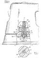
- the iron comprises a plastic casing 1 surmounting a heating sole 2.
- a vaporization chamber 3 is arranged between the upper face of the heating sole 2 and a sheet metal wall 6b.
- the heating sole 2 is traversed by steam distribution openings (not shown) through which the vaporization chamber 3 communicates with the outside, under the sole 2.
- the housing 1 contains a water tank 4 whose lower wall 6a, made of metal sheet, is located above the upper wall 6b of the chamber 3. Between the walls 6a and 6b is provided a space hollow 6c, having the aim of avoiding the heating of the water and the formation of vapor in the tank 4.
- the walls 6a and 6b are substantially horizontal in the iron service position in which the soleplate 2 is itself horizontal.
- An opening 7 passes through the walls 6a and 6b.
- the nozzle 8 of a water injection device 9 selectively allowing the water contained in the tank 4 to pass drop by drop by gravity into the vaporization chamber 3.
- the nozzle 8 comprises a tubular body 11 whose annular end directed towards the reservoir 4 has a flange 12 bearing, around the opening 7, under the sheet 6a adjacent to the tank 4.
- the sheet 6a itself around the opening 7 a cylindrical rim 13 fitted into the body 11.
- a metal tube 14 is crimped by its end directed towards the chamber 3 on the edge which presents around the opening 7 the sheet 6b adjacent to the chamber 3
- the tube 14 is fitted without play in the body 11 and extends to an annular wing 16 of the body 11, directed radially inwards.
- the body 11 is thus centered by the rim 13 and the tube 14, and it is positioned axially between the tube 14 and the sheet 6a.
- the wing 16 carries a flexible annular lip 17 delimiting by its free edge a circular orifice 18 ( Figure 2).
- the lip 17 is offset towards the tank 4 relative to the sheet 6b so as to be protected as much as possible from the heat given off by the heating sole 2.
- the wing 16 On its face facing the vaporization chamber 3, the wing 16 carries the inside the metal tube 14 a skirt 19 having a cylindrical inner wall with a diameter greater than that of the orifice 18. Over most of its axial length, the skirt 19 is surrounded by a free space 20 separating it radially from the tube 14 The space 20 extends to the free end 33 which the skirt 19 presents towards the chamber 3, and thus communicates with the chamber 3 all around the skirt 19.
- the end 33 of the skirt 19 protrudes from the tube 14 to the vaporization chamber 3.
- the body 11, the flange 12, the wing 16, the lip 17 and the skirt 19 are produced in a single block of silicone resin.
- the injection device 9 further comprises a needle 21 constituted by a rod of generally cylindrical shape made of a plastic material resistant to temperature.
- the rod 21 extends along the axis XX of the nozzle 8 and in particular of the orifice 18, this axis being perpendicular to the plane of the walls 6a and 6b and of the heating sole 2.
- the needle 21 is fixed to a pusher 22 mounted to slide along the axis XX in a barrel 23.
- the pusher 22 is connected to a push button 24 projecting from the top of the housing 1.
- the needle 21 comprises in the vicinity of the pusher 22 a lateral recess 26 constituted by a groove directed parallel to the axis XX.
- the area of the section of the groove 26 considered in a plane perpendicular to the axis XX decreases in the direction of the heating sole 2. This can be seen in Figures 1 and 4 from the decreasing depth of the groove 26. Between its groove 26 and its free end 27 directed towards the sole 2, the needle 21 has a smooth cylindrical region 28. The diameter of the needle 21 in the region having the groove 26 and in the region 28 is greater than the diameter of the orifice 18 before mounting of the needle 21, and is less than the internal diameter of the skirt 19.
- the needle 21 constantly tends to return to a closed position ( Figure 1) in which the lip 17 surrounds the smooth cylindrical region 28 of the needle 21. In this position, the needle 21 closes the orifice 18 and consequently prevents the flow of water to the vaporization chamber 3.
- the button 24 By pressing the button 24 ( Figure 4) the user can move the needle 21 along the axis XX until the lip 17 surrounds the needle 21 in the region having the groove 26. Therefore ( Figures 4 and 5 ) the groove 26 allows, through the orifice 18, a calibrated leak from the reservoir 4 towards the vaporization chamber 3. Taking into account the non-constant section of the groove 26, the flow rate to the vaporization chamber 3 is all the more important that the needle 21 is strongly moved towards the sole 2, which the user can adjust by pressing button 24 more or less.
- the flexible lip 17 is biased in bending by the axial movements of the needle 21, which descales it.
- the water which reaches the end 33 falls into the chamber 3 instead of spreading laterally towards the tube 14 and of forming scale in this region.
- the formation of tartar is therefore reduced.
- a tubular deposit is formed inside the skirt 19 having in section the shape shown in dotted lines at 29 in FIG. 1 and if no provision is made against a fair deposit 29, the needle 21 is braked or blocked in its movements; in addition, the scale deposit can seal between the skirt 19 and the needle 21 and thus prevent flow even when the needle 21 is in the injection position.
- the lip 17 in the plane of the sheet 6b, but this would have the disadvantage of subjecting it more to heating by the sole 2.
- the needle 21 would be too close to the sole 2 in the injection position.
- the skirt 19 has in the radial direction a thickness allowing it a certain flexibility taking into account the material (silicone resin) in which it is made.
- the needle 21 has at its free end 27 directed towards the sole 2, an annular bulge 31 having, in section along a plane passing through the axis XX, an isosceles triangle section whose base is parallel to the axis XX.
- the outside diameter of the bulge 31 is less than the inside diameter of the skirt 19.
- the bulge 31 has an outside diameter allowing it to cross the lip 17 by simple elastic deformation of the latter, which makes it possible to disassemble the needle 21 from above for cleaning.
- the bulge 31 When the needle 21 is in the closed position, the bulge 31 is surrounded by the skirt 19 ( Figure 1).
- the distance between the bulge 31 and the axial end 32 presented by the groove 26 in the direction of the bulge 31 is greater than or equal (equal in the example shown) to the distance between the lip 17 and the annular end 33 that has the skirt 19 on the downstream side, that is to say towards the sole 2.
- the bulge can be located below the free end of the needle and it can have a profile different from that described and shown.
Landscapes
- Engineering & Computer Science (AREA)
- Textile Engineering (AREA)
- Irons (AREA)
- Nozzles (AREA)
Claims (8)
Applications Claiming Priority (2)
| Application Number | Priority Date | Filing Date | Title |
|---|---|---|---|
| FR8417875 | 1984-11-23 | ||
| FR8417875A FR2573783B1 (fr) | 1984-11-23 | 1984-11-23 | Dispositif d'injection d'eau pour fer a repasser a vapeur |
Publications (2)
| Publication Number | Publication Date |
|---|---|
| EP0184496A1 EP0184496A1 (de) | 1986-06-11 |
| EP0184496B1 true EP0184496B1 (de) | 1988-05-04 |
Family
ID=9309881
Family Applications (1)
| Application Number | Title | Priority Date | Filing Date |
|---|---|---|---|
| EP85402276A Expired EP0184496B1 (de) | 1984-11-23 | 1985-11-22 | Wassereinspritzvorrichtung für Dampfbügeleisen |
Country Status (7)
| Country | Link |
|---|---|
| US (1) | US4669207A (de) |
| EP (1) | EP0184496B1 (de) |
| JP (1) | JPS61131800A (de) |
| CA (1) | CA1257533A (de) |
| DE (1) | DE3562495D1 (de) |
| ES (1) | ES290372Y (de) |
| FR (1) | FR2573783B1 (de) |
Families Citing this family (7)
| Publication number | Priority date | Publication date | Assignee | Title |
|---|---|---|---|---|
| FR2655667B1 (fr) * | 1989-12-13 | 1992-02-21 | Seb Sa | Dispositif d'injection d'eau pour fer a repasser a vapeur et fer a repasser a vapeur comportant un tel dispositif. |
| DE4402683A1 (de) * | 1994-01-29 | 1995-08-03 | Braun Ag | Wassereinleitvorrichtung für Dampfbügeleisen |
| US5623775A (en) * | 1996-01-16 | 1997-04-29 | Black & Decker Inc. | Electric steam iron with improved water tank and skirt assembly |
| US5829175A (en) * | 1996-09-20 | 1998-11-03 | Black & Decker Inc. | Steam iron with all temperature steam production |
| FR2776680B1 (fr) * | 1998-03-27 | 2001-09-28 | Moulinex Sa | Fer a repasser a vapeur |
| FR2802220B1 (fr) * | 1999-12-14 | 2002-01-18 | Seb Sa | Boisseau de fer a repasser a tige ceramique |
| DE102007062015B4 (de) | 2007-12-21 | 2014-11-06 | BSH Bosch und Siemens Hausgeräte GmbH | Ventilstange für Bügeleisen |
Family Cites Families (14)
| Publication number | Priority date | Publication date | Assignee | Title |
|---|---|---|---|---|
| DE374847C (de) * | 1921-07-15 | 1923-05-02 | Otto Walker | Elektrisches Buegeleisen |
| FR602293A (fr) * | 1925-08-19 | 1926-03-16 | Fer électrique à repasser, avec dispositif d'humidification du tissu | |
| US2746183A (en) * | 1951-02-21 | 1956-05-22 | Steam Iron Corp | Valve for steam iron |
| US2887799A (en) * | 1956-06-04 | 1959-05-26 | American Electrical Heater Co | Steam iron |
| FR1316012A (fr) * | 1962-01-17 | 1963-01-25 | Jura Elektroapp Fabriken L Hen | Perfectionnement aux fers à repasser à vapeur |
| CH448004A (de) * | 1965-12-09 | 1967-12-15 | Jura Elektroapparate Fab | Tropfventil für Dampfbügeleisen |
| US3474552A (en) * | 1968-06-24 | 1969-10-28 | Gen Electric | Steam iron valve structure |
| US3496661A (en) * | 1968-06-24 | 1970-02-24 | Gen Electric | Steam iron water valve structure |
| CH564633A5 (de) * | 1972-03-21 | 1975-07-31 | Henzirohs L Jura Elektroappara | |
| US3758969A (en) * | 1972-03-27 | 1973-09-18 | Gen Electric | Fast start spray iron |
| US3849916A (en) * | 1972-11-10 | 1974-11-26 | Gen Electric | Self-cleaning steam iron |
| US3889406A (en) * | 1974-10-07 | 1975-06-17 | Hoover Co | Steam iron water valve and manual operating mechanism therefor |
| PT66021B (de) * | 1976-02-05 | 1978-06-19 | Rowenta Werke Gmbh | Tropfventil fur dampfbugelautomaten |
| FR2449157A1 (fr) * | 1979-02-13 | 1980-09-12 | Seb Sa | Dispositif d'injection d'eau pour fer a repasser a vapeur, et fer a repasser a vapeur s'y rapportant |
-
1984
- 1984-11-23 FR FR8417875A patent/FR2573783B1/fr not_active Expired
-
1985
- 1985-11-18 ES ES1985290372U patent/ES290372Y/es not_active Expired
- 1985-11-19 CA CA000495645A patent/CA1257533A/en not_active Expired
- 1985-11-20 US US06/800,168 patent/US4669207A/en not_active Expired - Fee Related
- 1985-11-21 JP JP60259917A patent/JPS61131800A/ja active Granted
- 1985-11-22 EP EP85402276A patent/EP0184496B1/de not_active Expired
- 1985-11-22 DE DE8585402276T patent/DE3562495D1/de not_active Expired
Also Published As
| Publication number | Publication date |
|---|---|
| ES290372U (es) | 1986-10-16 |
| JPS61131800A (ja) | 1986-06-19 |
| ES290372Y (es) | 1987-06-16 |
| FR2573783A1 (fr) | 1986-05-30 |
| CA1257533A (en) | 1989-07-18 |
| FR2573783B1 (fr) | 1987-03-20 |
| DE3562495D1 (en) | 1988-06-09 |
| JPS6344399B2 (de) | 1988-09-05 |
| EP0184496A1 (de) | 1986-06-11 |
| US4669207A (en) | 1987-06-02 |
Similar Documents
| Publication | Publication Date | Title |
|---|---|---|
| EP0119181B1 (de) | Verteiler oder Tropfer für die Feinbewässerung von Böden | |
| EP0184496B1 (de) | Wassereinspritzvorrichtung für Dampfbügeleisen | |
| FR2771614A1 (fr) | Porte-filtre pour cafetiere du type expresso | |
| EP0520114B1 (de) | Unterbrechbarer Spülmechanismus mit gesicherter Minimalspülung | |
| FR2462200A1 (fr) | Godet pour pistolet de projection de peinture | |
| FR2825282A1 (fr) | Robinet d'arret pour endoscope avec element d'arret | |
| FR2735188A1 (fr) | Dispositif a pompe pour prelever un liquide dans un recipient et le distribuer sous forme pulverisee | |
| EP0486373B1 (de) | Viehtränke | |
| FR2712611A1 (fr) | Générateur de vapeur pour fer à repasser . | |
| EP1213038B1 (de) | Feuerschlauch mit einem Sicherungsgerät zum Verhindern, dass sich der Schlauch unter dem ihm speisenden Wasserdruck bewegt | |
| EP0575213B1 (de) | Ausgabevorrichtung für flüssige Produkte | |
| EP1317575A2 (de) | Selbstreinigendes dampfbügeleisen | |
| CA2261366C (fr) | Abreuvoir individuel a connexion pluridirectionnelle du genre comportant un bol et une robinetterie | |
| FR2731260A1 (fr) | Soupape d'equilibre de pression pour un reservoir de carburant | |
| FR2909295A1 (fr) | Pulverisateur portatif. | |
| FR2660679A1 (fr) | Dispositif de commande a bouton-poussoir et came basculante pour mecanisme de chasse d'eau. | |
| CH665347A5 (en) | Oral hygiene spray device - has spray head connectable to pressurised liq. supply, with selective control between multiple and single between multiple and single jets | |
| FR2741134A1 (fr) | Poignee de commande d'un robinet a verrou inviolable et robinet equipe d'une telle poignee | |
| EP0126667B1 (de) | Rohrtränken für Tiere | |
| BE895982A (fr) | Distributeur de micro-irrigation, auto-filtrant, auto-regulant et auto-nettoyant | |
| EP0719969A1 (de) | Sicherheitsventil | |
| EP1003409A1 (de) | Filterträger mit einer getränketropfen-zurückhaltungsvorrichtung, und kaffeemaschine mit einem solchen filterträger | |
| BE535192A (de) | ||
| FR2852375A3 (fr) | Soupape de vapeur pour cafetiere. | |
| CA2501829A1 (fr) | Pulverisateur a poussoir muni d'une buse laterale saillante |
Legal Events
| Date | Code | Title | Description |
|---|---|---|---|
| PUAI | Public reference made under article 153(3) epc to a published international application that has entered the european phase |
Free format text: ORIGINAL CODE: 0009012 |
|
| 17P | Request for examination filed |
Effective date: 19851127 |
|
| AK | Designated contracting states |
Kind code of ref document: A1 Designated state(s): BE DE FR GB IT LU NL |
|
| 17Q | First examination report despatched |
Effective date: 19870924 |
|
| ITF | It: translation for a ep patent filed | ||
| GRAA | (expected) grant |
Free format text: ORIGINAL CODE: 0009210 |
|
| AK | Designated contracting states |
Kind code of ref document: B1 Designated state(s): BE DE FR GB IT LU NL |
|
| REF | Corresponds to: |
Ref document number: 3562495 Country of ref document: DE Date of ref document: 19880609 |
|
| GBT | Gb: translation of ep patent filed (gb section 77(6)(a)/1977) | ||
| PLBE | No opposition filed within time limit |
Free format text: ORIGINAL CODE: 0009261 |
|
| STAA | Information on the status of an ep patent application or granted ep patent |
Free format text: STATUS: NO OPPOSITION FILED WITHIN TIME LIMIT |
|
| 26N | No opposition filed | ||
| PGFP | Annual fee paid to national office [announced via postgrant information from national office to epo] |
Ref country code: LU Payment date: 19910925 Year of fee payment: 7 |
|
| PGFP | Annual fee paid to national office [announced via postgrant information from national office to epo] |
Ref country code: BE Payment date: 19911024 Year of fee payment: 7 |
|
| ITTA | It: last paid annual fee | ||
| PGFP | Annual fee paid to national office [announced via postgrant information from national office to epo] |
Ref country code: NL Payment date: 19911130 Year of fee payment: 7 |
|
| EPTA | Lu: last paid annual fee | ||
| PG25 | Lapsed in a contracting state [announced via postgrant information from national office to epo] |
Ref country code: LU Free format text: LAPSE BECAUSE OF NON-PAYMENT OF DUE FEES Effective date: 19921122 |
|
| PG25 | Lapsed in a contracting state [announced via postgrant information from national office to epo] |
Ref country code: BE Effective date: 19921130 |
|
| BERE | Be: lapsed |
Owner name: S.A. SEB Effective date: 19921130 |
|
| PG25 | Lapsed in a contracting state [announced via postgrant information from national office to epo] |
Ref country code: NL Effective date: 19930601 |
|
| NLV4 | Nl: lapsed or anulled due to non-payment of the annual fee | ||
| REG | Reference to a national code |
Ref country code: GB Ref legal event code: IF02 |
|
| PGFP | Annual fee paid to national office [announced via postgrant information from national office to epo] |
Ref country code: FR Payment date: 20040913 Year of fee payment: 20 |
|
| PGFP | Annual fee paid to national office [announced via postgrant information from national office to epo] |
Ref country code: GB Payment date: 20041117 Year of fee payment: 20 |
|
| PGFP | Annual fee paid to national office [announced via postgrant information from national office to epo] |
Ref country code: DE Payment date: 20041208 Year of fee payment: 20 |
|
| PG25 | Lapsed in a contracting state [announced via postgrant information from national office to epo] |
Ref country code: GB Free format text: LAPSE BECAUSE OF EXPIRATION OF PROTECTION Effective date: 20051121 |
|
| REG | Reference to a national code |
Ref country code: GB Ref legal event code: PE20 |