EP0184520A2 - Verfahren zum Herstellen von Formen für Schiffrümpfe und ähnliche dünne Gegenstände und so erhaltene Formen - Google Patents
Verfahren zum Herstellen von Formen für Schiffrümpfe und ähnliche dünne Gegenstände und so erhaltene Formen Download PDFInfo
- Publication number
- EP0184520A2 EP0184520A2 EP85402428A EP85402428A EP0184520A2 EP 0184520 A2 EP0184520 A2 EP 0184520A2 EP 85402428 A EP85402428 A EP 85402428A EP 85402428 A EP85402428 A EP 85402428A EP 0184520 A2 EP0184520 A2 EP 0184520A2
- Authority
- EP
- European Patent Office
- Prior art keywords
- mold
- resin
- sheet
- layer
- shell
- Prior art date
- Legal status (The legal status is an assumption and is not a legal conclusion. Google has not performed a legal analysis and makes no representation as to the accuracy of the status listed.)
- Withdrawn
Links
- 238000000034 method Methods 0.000 title claims description 6
- 238000010438 heat treatment Methods 0.000 claims abstract description 28
- 239000004744 fabric Substances 0.000 claims abstract description 15
- 239000011521 glass Substances 0.000 claims abstract description 15
- 239000002131 composite material Substances 0.000 claims abstract description 12
- 239000002184 metal Substances 0.000 claims abstract description 10
- 238000000465 moulding Methods 0.000 claims abstract description 6
- 239000011810 insulating material Substances 0.000 claims abstract description 3
- 239000011347 resin Substances 0.000 claims description 15
- 229920005989 resin Polymers 0.000 claims description 15
- 239000000853 adhesive Substances 0.000 claims description 7
- 238000004519 manufacturing process Methods 0.000 claims description 7
- 240000002228 Cynara humilis Species 0.000 description 11
- 235000005921 Cynara humilis Nutrition 0.000 description 11
- 101100495270 Caenorhabditis elegans cdc-26 gene Proteins 0.000 description 10
- 239000012528 membrane Substances 0.000 description 10
- 239000006260 foam Substances 0.000 description 5
- 235000008429 bread Nutrition 0.000 description 4
- 239000010410 layer Substances 0.000 description 4
- 241001639412 Verres Species 0.000 description 3
- 239000000835 fiber Substances 0.000 description 3
- 230000000135 prohibitive effect Effects 0.000 description 3
- 238000007493 shaping process Methods 0.000 description 3
- 210000001519 tissue Anatomy 0.000 description 3
- 241000195940 Bryophyta Species 0.000 description 2
- 229920002302 Nylon 6,6 Polymers 0.000 description 2
- 208000002193 Pain Diseases 0.000 description 2
- 239000004952 Polyamide Substances 0.000 description 2
- 240000008042 Zea mays Species 0.000 description 2
- 239000011248 coating agent Substances 0.000 description 2
- 238000000576 coating method Methods 0.000 description 2
- 230000000694 effects Effects 0.000 description 2
- 239000007788 liquid Substances 0.000 description 2
- 239000000463 material Substances 0.000 description 2
- 239000007769 metal material Substances 0.000 description 2
- 235000011929 mousse Nutrition 0.000 description 2
- 230000036407 pain Effects 0.000 description 2
- 229920002647 polyamide Polymers 0.000 description 2
- OKTJSMMVPCPJKN-UHFFFAOYSA-N Carbon Chemical compound [C] OKTJSMMVPCPJKN-UHFFFAOYSA-N 0.000 description 1
- 229920000271 Kevlar® Polymers 0.000 description 1
- 229920005830 Polyurethane Foam Polymers 0.000 description 1
- 229910000831 Steel Inorganic materials 0.000 description 1
- 241001080024 Telles Species 0.000 description 1
- 229920000561 Twaron Polymers 0.000 description 1
- 239000006096 absorbing agent Substances 0.000 description 1
- 230000006978 adaptation Effects 0.000 description 1
- 239000002390 adhesive tape Substances 0.000 description 1
- 239000004760 aramid Substances 0.000 description 1
- 229920003235 aromatic polyamide Polymers 0.000 description 1
- 229910052799 carbon Inorganic materials 0.000 description 1
- 239000011247 coating layer Substances 0.000 description 1
- 238000010411 cooking Methods 0.000 description 1
- 238000001816 cooling Methods 0.000 description 1
- 229940082150 encore Drugs 0.000 description 1
- 239000003365 glass fiber Substances 0.000 description 1
- 239000003292 glue Substances 0.000 description 1
- 229920001903 high density polyethylene Polymers 0.000 description 1
- 239000004700 high-density polyethylene Substances 0.000 description 1
- 238000009434 installation Methods 0.000 description 1
- 238000009413 insulation Methods 0.000 description 1
- 239000012212 insulator Substances 0.000 description 1
- 238000002955 isolation Methods 0.000 description 1
- 239000004761 kevlar Substances 0.000 description 1
- 239000011490 mineral wool Substances 0.000 description 1
- 239000002245 particle Substances 0.000 description 1
- 238000005192 partition Methods 0.000 description 1
- 239000004033 plastic Substances 0.000 description 1
- 229920003023 plastic Polymers 0.000 description 1
- 239000011120 plywood Substances 0.000 description 1
- 239000004848 polyfunctional curative Substances 0.000 description 1
- 229920002635 polyurethane Polymers 0.000 description 1
- 239000004814 polyurethane Substances 0.000 description 1
- 239000011496 polyurethane foam Substances 0.000 description 1
- -1 polyéthylène Polymers 0.000 description 1
- 239000002904 solvent Substances 0.000 description 1
- 239000010959 steel Substances 0.000 description 1
- 239000003351 stiffener Substances 0.000 description 1
- 239000004762 twaron Substances 0.000 description 1
- 239000002023 wood Substances 0.000 description 1
Images
Classifications
-
- B—PERFORMING OPERATIONS; TRANSPORTING
- B29—WORKING OF PLASTICS; WORKING OF SUBSTANCES IN A PLASTIC STATE IN GENERAL
- B29C—SHAPING OR JOINING OF PLASTICS; SHAPING OF MATERIAL IN A PLASTIC STATE, NOT OTHERWISE PROVIDED FOR; AFTER-TREATMENT OF THE SHAPED PRODUCTS, e.g. REPAIRING
- B29C33/00—Moulds or cores; Details thereof or accessories therefor
- B29C33/34—Moulds or cores; Details thereof or accessories therefor movable, e.g. to or from the moulding station
-
- B—PERFORMING OPERATIONS; TRANSPORTING
- B29—WORKING OF PLASTICS; WORKING OF SUBSTANCES IN A PLASTIC STATE IN GENERAL
- B29C—SHAPING OR JOINING OF PLASTICS; SHAPING OF MATERIAL IN A PLASTIC STATE, NOT OTHERWISE PROVIDED FOR; AFTER-TREATMENT OF THE SHAPED PRODUCTS, e.g. REPAIRING
- B29C33/00—Moulds or cores; Details thereof or accessories therefor
- B29C33/02—Moulds or cores; Details thereof or accessories therefor with incorporated heating or cooling means
-
- B—PERFORMING OPERATIONS; TRANSPORTING
- B29—WORKING OF PLASTICS; WORKING OF SUBSTANCES IN A PLASTIC STATE IN GENERAL
- B29C—SHAPING OR JOINING OF PLASTICS; SHAPING OF MATERIAL IN A PLASTIC STATE, NOT OTHERWISE PROVIDED FOR; AFTER-TREATMENT OF THE SHAPED PRODUCTS, e.g. REPAIRING
- B29C70/00—Shaping composites, i.e. plastics material comprising reinforcements, fillers or preformed parts, e.g. inserts
- B29C70/04—Shaping composites, i.e. plastics material comprising reinforcements, fillers or preformed parts, e.g. inserts comprising reinforcements only, e.g. self-reinforcing plastics
- B29C70/28—Shaping operations therefor
- B29C70/30—Shaping by lay-up, i.e. applying fibres, tape or broadsheet on a mould, former or core; Shaping by spray-up, i.e. spraying of fibres on a mould, former or core
- B29C70/34—Shaping by lay-up, i.e. applying fibres, tape or broadsheet on a mould, former or core; Shaping by spray-up, i.e. spraying of fibres on a mould, former or core and shaping or impregnating by compression, i.e. combined with compressing after the lay-up operation
- B29C70/342—Shaping by lay-up, i.e. applying fibres, tape or broadsheet on a mould, former or core; Shaping by spray-up, i.e. spraying of fibres on a mould, former or core and shaping or impregnating by compression, i.e. combined with compressing after the lay-up operation using isostatic pressure
-
- H—ELECTRICITY
- H05—ELECTRIC TECHNIQUES NOT OTHERWISE PROVIDED FOR
- H05B—ELECTRIC HEATING; ELECTRIC LIGHT SOURCES NOT OTHERWISE PROVIDED FOR; CIRCUIT ARRANGEMENTS FOR ELECTRIC LIGHT SOURCES, IN GENERAL
- H05B3/00—Ohmic-resistance heating
- H05B3/10—Heating elements characterised by the composition or nature of the materials or by the arrangement of the conductor
- H05B3/12—Heating elements characterised by the composition or nature of the materials or by the arrangement of the conductor characterised by the composition or nature of the conductive material
-
- B—PERFORMING OPERATIONS; TRANSPORTING
- B29—WORKING OF PLASTICS; WORKING OF SUBSTANCES IN A PLASTIC STATE IN GENERAL
- B29C—SHAPING OR JOINING OF PLASTICS; SHAPING OF MATERIAL IN A PLASTIC STATE, NOT OTHERWISE PROVIDED FOR; AFTER-TREATMENT OF THE SHAPED PRODUCTS, e.g. REPAIRING
- B29C43/00—Compression moulding, i.e. applying external pressure to flow the moulding material; Apparatus therefor
- B29C43/02—Compression moulding, i.e. applying external pressure to flow the moulding material; Apparatus therefor of articles of definite length, i.e. discrete articles
- B29C43/10—Isostatic pressing, i.e. using non-rigid pressure-exerting members against rigid parts or dies
- B29C43/12—Isostatic pressing, i.e. using non-rigid pressure-exerting members against rigid parts or dies using bags surrounding the moulding material or using membranes contacting the moulding material
Definitions
- the invention relates to the molding of thin pieces of the type of shell which are made of a "composite” material, that is to say composed of sheets of glass fabric or the like impregnated with resin on the one hand and the other part of filling elements such as foam bars or wooden blocks.
- a "composite” material that is to say composed of sheets of glass fabric or the like impregnated with resin on the one hand and the other part of filling elements such as foam bars or wooden blocks.
- these heating mats consist of thin steel tapes individually wrapped in insulating sheaths and held parallel to each other by means of glass fiber bands intertwined in these ribbons, said ribbons being mounted electrically in parallel with each other using electric current distribution bars connected to the ends of these ribbons.
- the object of the invention is, above all, to overcome these drawbacks by making it possible to mold very large hulls, such as the hulls of boats of length greater than 10 meters, this length possibly reaching or even exceeding 50 meters.
- the molds under consideration also include a heating mat comprising parallel thin metal strips surrounded by insulating material and electrically connected to each other and the methods of manufacturing these molds are essentially characterized according to the invention in that they are shaped on site, on a suitable rigid support, a first sheet of glass fabric or the like impregnated with resin, in that it is unrolled on this first sheet a self-adhesive metal strip provided on one of its faces, with its self-adhesive side facing the sheet, so as to form a series of parallel strands glued onto said sheet, and in that the whole is covered by a second sheet of glass cloth or the like impregnated with resin.
- the metal strip is folded twice at 90 degrees during unwinding at the ends of the successive parallel strands so as to obtain a series of strands connected together in series according to zigzags.
- the mold meanwhile, has the characteristics arising from the processes thus defined.
- the metal strips which constitute the electrical resistances of its heating mat are made of lead and have a width of between 10 and 50 mm and a thickness of between 0.1 and 0.5 mm.
- the invention includes, apart from these main provisions, certain other provisions which are preferably used at the same time and which will be more explicitly discussed below.
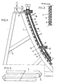
- a hull 1 of a very long boat for example of length greater than 30 meters, made of "composite”.
- the blocks 2 in question are prismatic breads of trapezoidal section individually wrapped by sheets 3 as defined above, these breads are juxtaposed side by side along their lateral faces and the assembly is inserted between two parallel sheets 3 of the above type.
- the thickness of the shell 1 is of the order of 5 cm for a length of the order of 30 meters.
- the calories necessary for heating the blank are brought directly against the two faces of this blank using electrically heated mats 4 applied contiguously against these two faces.
- Said mats 4 are sheets filled with electrical resistances capable of generating calories by the Joule effect.
- These resistors consist of flat lead strips 5 having a width of between 10 and 50 mm, preferably of the order of 25 mm and a thickness of between 0.1 and 0.5 mm, preferably of the order 0.2 mm.
- These bands 5 extend horizontally parallel to each other, with a mutual distance which is of the order of half their width and they are connected together in series at their ends in a zigzag.
- connection is advantageously obtained by double folding of the strip at 90 * , as seen at 5 in FIG. 3.
- the strips 5 are inserted between two thin sheets 6 (FIG. 2) made of composite, that is to say each constituted by a glass cloth or the like embedded in a resin, said sheets 6 being applied one against the other. .
- the strips 5 can then be available in the form of rolls, as is well known for the adhesive tapes.
- Each heating mat 4 the thickness of which is in particular of the order of 3 mm, is resistant to the temperatures involved in molding and preferably made permeable to vapors and liquids by perforation.
- the resin which constitutes the sheets 6 can for this purpose be a cold-polymerizable tooling resin with hardener.
- the membrane 15 is extended at its periphery by folded edges 17 which surround the shell 1 and which are tightly assembled against the periphery of the mold.
- This assembly is to produce a waterproof deformable pocket containing both the shell 1 and the two heating mats 4.
- the shell to be manufactured comprises, in addition to its relatively thin running portions with parallel faces, inserts 19 having portions 20 projecting towards the interior of the hull, portions intended to subsequently constitute expectations for partitions or floors or stiffeners.
- inserts are made of non-metallic materials, preferably using foam and / or wooden parts and glass or similar fabrics impregnated with resin.
- said inserts 19 are enveloped over their entire extent by the various sheets constituting the counter-mold 8, and in particular by the heating mat 4 and the membrane 15 constituting this counter-mold.
- the maximum temperature is of the order of 120 * and is reached in stages after a period of the order of 8 to 9 hours.
- the invention is in no way limited to those of its modes of application and embodiments which have been more especially envisaged; on the contrary, it embraces all of its variants, in particular those in which the glass fabric would be replaced by a set of threads of fibers of comparable qualities such as fibers made of carbon, or else of an aramid such as that diffused under the Kevlar appellation by the cios du Pont de Nemours or that distributed under the Twaron appellation by the Akzo Company.
Landscapes
- Engineering & Computer Science (AREA)
- Mechanical Engineering (AREA)
- Chemical & Material Sciences (AREA)
- Composite Materials (AREA)
- Casting Or Compression Moulding Of Plastics Or The Like (AREA)
- Laminated Bodies (AREA)
Applications Claiming Priority (2)
| Application Number | Priority Date | Filing Date | Title |
|---|---|---|---|
| FR8418764A FR2574341B1 (fr) | 1984-12-07 | 1984-12-07 | Perfectionnements aux procedes et dispositifs de fabrication des coques et pieces minces analogues et aux pieces ainsi fabriquees |
| FR8418764 | 1984-12-07 |
Publications (2)
| Publication Number | Publication Date |
|---|---|
| EP0184520A2 true EP0184520A2 (de) | 1986-06-11 |
| EP0184520A3 EP0184520A3 (de) | 1987-08-26 |
Family
ID=9310376
Family Applications (1)
| Application Number | Title | Priority Date | Filing Date |
|---|---|---|---|
| EP85402428A Withdrawn EP0184520A3 (de) | 1984-12-07 | 1985-12-06 | Verfahren zum Herstellen von Formen für Schiffrümpfe und ähnliche dünne Gegenstände und so erhaltene Formen |
Country Status (2)
| Country | Link |
|---|---|
| EP (1) | EP0184520A3 (de) |
| FR (1) | FR2574341B1 (de) |
Cited By (2)
| Publication number | Priority date | Publication date | Assignee | Title |
|---|---|---|---|---|
| WO1999035888A1 (en) * | 1998-01-09 | 1999-07-15 | Ceramitech, Inc. | Electric heating device |
| US6146576A (en) * | 1994-08-08 | 2000-11-14 | Intralaminar Heat Cure, Inc. | Method of forming advanced cured resin composite parts |
Families Citing this family (1)
| Publication number | Priority date | Publication date | Assignee | Title |
|---|---|---|---|---|
| SE464514B (sv) * | 1989-03-20 | 1991-05-06 | Diab Barracuda Ab | Saett att tillverka baatskrov av plast i sandwichkonstruktion |
Family Cites Families (15)
| Publication number | Priority date | Publication date | Assignee | Title |
|---|---|---|---|---|
| CA674309A (en) * | 1963-11-19 | D. Napier And Son Limited | Electrical surface heaters | |
| US2418438A (en) * | 1944-11-17 | 1947-04-01 | Vilas E Watts | Method for producing curved laminated structures |
| US2714567A (en) * | 1952-10-17 | 1955-08-02 | Pittsburgh Plate Glass Co | Preliminary pressing of bent laminated glass |
| GB765709A (en) * | 1953-09-02 | 1957-01-09 | William Olgilvie Hay | Improved room electric heater |
| GB863928A (en) * | 1958-08-04 | 1961-03-29 | Norsk Eswa As | Improvements in room heating elements |
| DD98416A1 (de) * | 1971-07-30 | 1973-06-12 | ||
| GB1386894A (en) * | 1972-10-13 | 1975-03-12 | Statni Vyzkumny Ustav Textilni | Method of producing an electrically heated sheet |
| GB1366148A (en) * | 1972-11-08 | 1974-09-11 | Wredden J V H | Electrical panel heater |
| US3964958A (en) * | 1973-01-24 | 1976-06-22 | Johnston Orin B | Heat bonding device |
| FR2228589A2 (en) * | 1973-05-07 | 1974-12-06 | Aerospatiale | Heating blanket for curing mould lay ups from both faces - to reduce cure temp. cycles and differentials |
| FR2251151A1 (en) * | 1973-11-09 | 1975-06-06 | Triplet Albert | Electrically heater plate for incubation chamber - has resistance wire embedded in plastics sheet |
| DE2650859C3 (de) * | 1976-11-06 | 1979-10-04 | Messerschmitt-Boelkow-Blohm Gmbh, 8000 Muenchen | Verfahren zur Herstellung von Großbauteilen aus faserverstärktem Kunststoff und Einrichtung zur Durchfuhrung des Verfahrens |
| DE3015998C2 (de) * | 1980-04-25 | 1983-05-19 | Messerschmitt-Bölkow-Blohm GmbH, 8000 München | Anordnung zur Beheizung großflächiger Laminatformkörper |
| NO146836C (no) * | 1980-10-10 | 1982-12-22 | Standard Tel Kabelfab As | Elektrisk varmeelement. |
| FR2552012B1 (fr) * | 1983-09-19 | 1986-12-12 | Aerospatiale | Procede de fabrication d'un moule pour realiser des pieces moulees de grandes dimensions en materiau composite, moule obtenu au moyen de ce procede et piece polymerisee obtenue au moyen de ce moule |
-
1984
- 1984-12-07 FR FR8418764A patent/FR2574341B1/fr not_active Expired
-
1985
- 1985-12-06 EP EP85402428A patent/EP0184520A3/de not_active Withdrawn
Cited By (3)
| Publication number | Priority date | Publication date | Assignee | Title |
|---|---|---|---|---|
| US6146576A (en) * | 1994-08-08 | 2000-11-14 | Intralaminar Heat Cure, Inc. | Method of forming advanced cured resin composite parts |
| WO1999035888A1 (en) * | 1998-01-09 | 1999-07-15 | Ceramitech, Inc. | Electric heating device |
| US6353707B1 (en) | 1998-01-09 | 2002-03-05 | Ceramitech, Inc. | Electric heating ribbon with multiple coating sections attached to ribbon |
Also Published As
| Publication number | Publication date |
|---|---|
| EP0184520A3 (de) | 1987-08-26 |
| FR2574341A1 (fr) | 1986-06-13 |
| FR2574341B1 (fr) | 1987-01-16 |
Similar Documents
| Publication | Publication Date | Title |
|---|---|---|
| EP0428885B1 (de) | Verfahren zur Herstellung eines Skis durch Injektion, und Skistruktur | |
| EP2878427B1 (de) | Herstellungsverfahren eines Bauteils aus Sandwich-Material, und nach diesem Verfahren hergestelltes Bauteil | |
| EP2259913B1 (de) | Verfahren und vorrichtung zum formen eines gebogenen bauteils aus verbundmaterial | |
| EP1224114B1 (de) | Baugruppe zum herstellen eines gleitschwimmkörpers und deren herstellungsverfahren | |
| EP2817223B1 (de) | Verfahren zur herstellung einer vorderkantenhülle durch backen eines stapels von erwärmungselementen und schichten von vorimprägnierten fasern | |
| CA2364951C (fr) | Procede de fabrication d'un panneau a couche d'amortissement acoustique protegee et panneau acoustique ainsi obtenu | |
| WO2011061432A1 (fr) | Procédé de fabrication d'une pièce courbe en matériau composite et dispositif pour la fabrication d'une pièce courbe en matériau composite | |
| EP2262634A2 (de) | Verfahren und vorrichtung zur herstellung eines gekrümmten teilstückes aus einem verbundwerkstoff und auf diese weise hergestelltes teilstück | |
| FR2602739A1 (fr) | Pale en materiaux composites, a structure bilongeron et bicaisson, et a revetement stratifies a sandwich de nid d'abeilles, et son procede de fabrication | |
| EP1071555A1 (de) | Verfahren zum herstellen, reparieren oder wiederherstellen eines gegenstandes mit einem teil oder material aus verbundwerkstoff | |
| EP2225099B1 (de) | Verfahren zur herstellung einer platte mit mindestens einem zellkörper und einer ersten haut aus einem verbundwerkstoff | |
| FR2612282A1 (fr) | Element de construction amovible ou pivotant pour l'habillage d'ouvertures dans le fuselage d'un avion | |
| EP3445578B1 (de) | Mehrschichtige platte | |
| CA2849707A1 (fr) | Procede pour etancher un reservoir de carburant | |
| EP0184520A2 (de) | Verfahren zum Herstellen von Formen für Schiffrümpfe und ähnliche dünne Gegenstände und so erhaltene Formen | |
| EP2412613B1 (de) | Karosseriemodul für ein Kühlfahrzeug mit Vakuum-Isolierpaneel, und entsprechendes Herstellungsverfahren | |
| EP3530444B1 (de) | Herstellungsverfahren eines zentralgehäuses eines flügels mithilfe von durch formpressverfahren mit hohem druck und niedriger temperatur hergestellten profilen, und zentralgehäuse eines flügels, das durch die umsetzung dieses verfahrens erhalten wurde | |
| EP2510514A1 (de) | Verfahren zur herstellung einer akustischen platte für eine triebwerksgondel eines flugzeuges | |
| WO2007048898A1 (fr) | Planche de glisse comportant une structure sandwich renforcée | |
| EP3018261B1 (de) | Vakuum-isolations-paneel (vip) mit wellen an der oberfläche, wandelement und wärmedämmwand, die ein solches paneel enthält | |
| FR2560819A1 (fr) | Panneau composite et procede concu pour la fabrication de ce panneau | |
| EP0308355B1 (de) | Selbsttragendes dekoratives Element aus leichter gemachtem Verbundmaterial und Verfahren zu seiner Herstellung | |
| FR2611519A1 (fr) | Procede pour realiser un ski et ski realise selon ce procede | |
| FR2490993A3 (fr) | Procede et dispositif pour la realisation de corps creux en matiere stratifiee et corps creux ainsi obtenus | |
| FR2704477A1 (fr) | Procédé de fabrication de plaques planes ondulées ou nervurées à base de résine thermodurcissable et dispositif pour la mise en Óoeuvre de ce procédé. |
Legal Events
| Date | Code | Title | Description |
|---|---|---|---|
| PUAI | Public reference made under article 153(3) epc to a published international application that has entered the european phase |
Free format text: ORIGINAL CODE: 0009012 |
|
| AK | Designated contracting states |
Kind code of ref document: A2 Designated state(s): DE FR GB IT NL SE |
|
| PUAL | Search report despatched |
Free format text: ORIGINAL CODE: 0009013 |
|
| AK | Designated contracting states |
Kind code of ref document: A3 Designated state(s): DE FR GB IT NL SE |
|
| STAA | Information on the status of an ep patent application or granted ep patent |
Free format text: STATUS: THE APPLICATION IS DEEMED TO BE WITHDRAWN |
|
| 18D | Application deemed to be withdrawn |
Effective date: 19880229 |
|
| RIN1 | Information on inventor provided before grant (corrected) |
Inventor name: CADOT, DANIEL Inventor name: INGOUF, LEON Inventor name: NEDELEC, GILLES |