EP0184545B1 - Verfahren und Vorrichtung zum Analysieren von Gasdiffusion - Google Patents
Verfahren und Vorrichtung zum Analysieren von Gasdiffusion Download PDFInfo
- Publication number
- EP0184545B1 EP0184545B1 EP85730159A EP85730159A EP0184545B1 EP 0184545 B1 EP0184545 B1 EP 0184545B1 EP 85730159 A EP85730159 A EP 85730159A EP 85730159 A EP85730159 A EP 85730159A EP 0184545 B1 EP0184545 B1 EP 0184545B1
- Authority
- EP
- European Patent Office
- Prior art keywords
- wind
- gas
- velocity
- tracer gas
- topography
- Prior art date
- Legal status (The legal status is an assumption and is not a legal conclusion. Google has not performed a legal analysis and makes no representation as to the accuracy of the status listed.)
- Expired
Links
- 238000009792 diffusion process Methods 0.000 title claims description 76
- 238000012360 testing method Methods 0.000 title claims description 61
- 238000000034 method Methods 0.000 title claims description 17
- 238000012876 topography Methods 0.000 claims description 72
- 239000000700 radioactive tracer Substances 0.000 claims description 61
- 238000007664 blowing Methods 0.000 claims description 15
- 238000007599 discharging Methods 0.000 claims description 13
- 238000010998 test method Methods 0.000 claims description 6
- 238000009877 rendering Methods 0.000 claims description 4
- 239000007789 gas Substances 0.000 description 139
- 239000000779 smoke Substances 0.000 description 22
- 230000001276 controlling effect Effects 0.000 description 6
- 238000005070 sampling Methods 0.000 description 5
- 230000000717 retained effect Effects 0.000 description 4
- 238000007789 sealing Methods 0.000 description 4
- 238000004140 cleaning Methods 0.000 description 3
- 238000003912 environmental pollution Methods 0.000 description 3
- 239000007788 liquid Substances 0.000 description 3
- 238000010276 construction Methods 0.000 description 2
- 238000007796 conventional method Methods 0.000 description 2
- 239000000446 fuel Substances 0.000 description 2
- 238000005192 partition Methods 0.000 description 2
- 230000001105 regulatory effect Effects 0.000 description 2
- 230000000630 rising effect Effects 0.000 description 2
- 238000011144 upstream manufacturing Methods 0.000 description 2
- 238000012935 Averaging Methods 0.000 description 1
- 230000033228 biological regulation Effects 0.000 description 1
- 238000010586 diagram Methods 0.000 description 1
- 230000000694 effects Effects 0.000 description 1
- 230000007613 environmental effect Effects 0.000 description 1
- 238000004868 gas analysis Methods 0.000 description 1
- 230000014759 maintenance of location Effects 0.000 description 1
- 238000012986 modification Methods 0.000 description 1
- 230000004048 modification Effects 0.000 description 1
- 238000005096 rolling process Methods 0.000 description 1
- 238000004088 simulation Methods 0.000 description 1
- 239000005341 toughened glass Substances 0.000 description 1
Images





Classifications
-
- G—PHYSICS
- G09—EDUCATION; CRYPTOGRAPHY; DISPLAY; ADVERTISING; SEALS
- G09B—EDUCATIONAL OR DEMONSTRATION APPLIANCES; APPLIANCES FOR TEACHING, OR COMMUNICATING WITH, THE BLIND, DEAF OR MUTE; MODELS; PLANETARIA; GLOBES; MAPS; DIAGRAMS
- G09B23/00—Models for scientific, medical, or mathematical purposes, e.g. full-sized devices for demonstration purposes
- G09B23/06—Models for scientific, medical, or mathematical purposes, e.g. full-sized devices for demonstration purposes for physics
- G09B23/08—Models for scientific, medical, or mathematical purposes, e.g. full-sized devices for demonstration purposes for physics for statics or dynamics
- G09B23/12—Models for scientific, medical, or mathematical purposes, e.g. full-sized devices for demonstration purposes for physics for statics or dynamics of liquids or gases
-
- G—PHYSICS
- G01—MEASURING; TESTING
- G01M—TESTING STATIC OR DYNAMIC BALANCE OF MACHINES OR STRUCTURES; TESTING OF STRUCTURES OR APPARATUS, NOT OTHERWISE PROVIDED FOR
- G01M9/00—Aerodynamic testing; Arrangements in or on wind tunnels
- G01M9/06—Measuring arrangements specially adapted for aerodynamic testing
Definitions
- the present invention relates to a method for testing gas diffusion by simulating gas diffusion situations of nature on a laboratory scale, and an apparatus for this method.
- a wind is caused to flow, and a specific gas, e.g., a tracer gas is discharged from the miniature chimneys.
- a specific gas e.g., a tracer gas
- an expansion of the gas is observed and measured by a color change test, a suction/gas analysis with the aid of a traverse, and the like.
- the topography model is rotatably disposed in the wind passage of the wind tunnel.
- a gas diffusion test can be carried out by previously establishing the time distribution of the direction and the velocity of the wind blowing above the central portion of its rotation and rotating the topography model on the basis of the established time distribution.
- FIG. 14 which represents the prior art disclosed in "Patent Abstracts of Japan, volume 7, No. 57 (P-181) (1202) 9 March 1983; JP-A-57 203 930 (Mitsub. Juko. K.K.) 14.12.1982, Abstract," an air flow 1 which has been generated by an air blower not shown and which has been rectified into a steady flow is blown into a wind passage 2 of a wind tunnel.
- a floor surface 3 of this wind passage 2 is provided at its central portion with a turntable 4 which is rotatably supported by a rotatable support device 12, the top surface of the turntable 4 being at the same level as the floor surface 3.
- a miniature chimney 5 is planted through the turntable 4.
- a topography model 6 comprising a building and the like is arranged on the turntable 4.
- a circumferential plate 9 is projectively disposed under the turntable 4 and is further immersed at its end portion in a sealing liquid 10 pooled in a circumferential groove member 8, which is attached to the circumferential edge of an opening formed in the floor surface 3.
- the turntable 4 can be rotated by a suitable means which is not shown, and a tracer gas 7 is discharged from the miniature chimney 5.
- a wind velocity of the wind which blows above the topography model 6 provided on the turntable 4 and a rotation angle of the turntable 4 can be decided as follows: That is to say, the direction and the velocity of the blowing wind are observed during one day on a chimney-disposed site or a construction-planned site to prepare such a wind rose as in Fig. 2, and the rotation angle of the turntable 4 and the velocity the blowing wind are regulated so as to reproduce the wind direction and the wind velocity of the wind rose.
- the height of the miniature chimney is decided on the basis of a reduced scale rate of the topography, and thus it is impossible to carry out the diffusion tests at the variously changed discharge heights.
- the wind tunnel is fixed and the topography model in the wind passage also is stationary. Therefore, in the one test, the gas diffusion can only be tested and measured under a specific condition such as the blow of a south wind.
- the topography model must be turned reversely in the wind tunnel.
- this topography model there are disposed a pipe for feeding the gas to the miniature chimney therethrough, a pipe for sucking the gas therethrough and the like, and thus returning the topography model reversely is difficult.
- each gas diffusion test must be carried out under each wind direction/wind velocity condition.
- the present invention has been achieved in view of such situations.
- the present invention is constituted as follows:
- the present invention is constituted as described above, and thus the following effects can be obtained.
- a turntable 4 is supported by means of a rotatable supporting device 12 in the middle of a floor surface 3.
- a miniature chimney 5 formed in a reduced scale ratio of a shown topography and a discharge pipe 5a an effective height He of which can be changed in response to the change in a wind velocity.
- a sealing medium is used, whereby the pipe 5a can freely move upward and downward without allowing any gas to leak out.
- the discharge pipe 5a is provided on its part with a rack 14 for enabling the pipe 5a to move upward and downward by the rotation of a gear 13, and is connected at its lower end portion to a pipe 16 for allowing a gas 7 to flow therethrough.
- the gear 13 can be driven by a motor not shown, and the rotation of the motor can be controlled by a control device 15. Therefore, when the height of the discharge pipe 5a is changed with time, the information of the height change is previously stored in the control device 15. Accordingly, the information in the control device 15 commands the motor to rotate and to thereby drive the discharge pipe 5a upward and downward.
- the other devices are the same as in a conventional one.
- Fig. 2 exhibits a frequency distribution in 16 directions, and a solid line therein represents the frequency distribution in each wind direction and a dotted line represents an average velocity of the wind in each direction. Since the average wind velocity for each wind direction is known from the shown dotted line, the discharge height He can previously be calculated for each wind velocity, for example, by the use of the formula for representing the rise of smoke. The information regarding a relation between a retention time of each wind direction and the discharge height is previously stored in the control device 15.
- a 1% wind direction frequency corresponds to 18 seconds. That is to say, the wind having the wind velocity shown by the dotted line in Fig. 2 is prepared in the wind tunnel.
- a discharge opening 17 is positioned at a level of the discharge height for this wind velocity, and the turntable 4 is rotated every 22.5° (360/16) in the 16 directions. In this case, each wind direction is maintained for a period of time corresponding to the wind direction frequency distribution of the wind rose in Fig. 2.
- the west side of the discharge pipe 5a on the turntable 4 is oriented to the upstream side of the wind passage and the discharge opening 17 is set at a level of the discharge height He for the wind velocity for the test. After the wind in the wind tunnel has been stabilized, the gas 7 is discharged from the discharge opening 17.
- the test of the diffusion state of the gas 7 can be carried out, for example, by a color change test method.
- the present invention can reproduce, on a laboratory scale, the time distribution of the wind direction and the wind velocity on the topography model in compliance with the weather conditions on an actual location. Further, according to the constitution of the present invention, the discharge height of the tracer gas can be positioned at the predetermined level in response to the wind velocity, whereby the diffusion state under natural conditions can be reproduced.
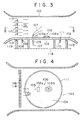
- a topography table 104 is provided in the middle of a floor surface 103 of the wind passage 102 into which there is blown an air stream 101 generated by air blowers 114 disposed between partitions 115,115 and then rectified into the state of a steady flow.
- the upper surface of the topography table 104 lies at the same level as the floor surface 103.
- On the topography table 104 there is placed a so-called topography model 106 containing a miniature chimney 105, a miniature building 106a, a miniature mountain 106b and the like, the model chimney 105 being planted through the topography table 104.
- a side plate of the wind passage 102 is made of a transparent tempered glass so that the interior of the wind passage 102 may be visible therethrough.
- the air flow 101 is rectified by the partitions 115 and rectifying plates 116.
- the floor surface 103 is supported by support columns 119 and rolling rollers 113 thereon, the support columns 119 being circularly arranged on the ground 118. Therefore, the wind passage 102 inclusive of the air blowers 114 can be freely rotated in a horizontal plane.
- a circumferential plate 109 is provided downward and is immersed in a sealing liquid 110 pooled in a circumferential groove 108 projectingly disposed along and under the circumferential edge of a central opening in the floor surface 103.
- This constitution thus permits preventing air from leaking out through a space between the floor surface 103 and the topography table 104.
- the wind passage 102 is rotated by a suitable means not shown, and a tracer gas 107 is discharged from the miniature chimney 105.
- the wind which will blow on the intensive topography model on the topography table 104 can be previously decided as follows:
- a wind blowing at, for example, 4to 6 m/ s for one day is measured in 16 directions to prepare a wind rose shown in Fig. 5.
- the frequency distribution is indicated in terms of percent, and for example, if it is intended that the gas diffusion for one day is carried out in 30 minutes, a value of 1% corresponds to 18 seconds.
- the wind having a wind velocity corresponding to an actual 5 m/s velocity is prepared in the wind passage 102 and the latter is rotated every 22.5° to the surface of the topography table 104 in order to retain the air stream 101 at a predetermined position for a period of time in compliance with the frequency distribution shown in the wind rose in Fig. 5.
- the gas diffusion begins with a west wind
- the west side of the miniature chimney 105 on the topography table 104 is oriented to the upstream of the air stream 101 in the wind passage 102, and when the wind in the wind tunnel has been stabilized, the tracer gas 107 is then discharged.
- a diffusion test is continued for 144 (8x 18) seconds in this state, and afterward, the wind passage 102 is rotated clockwise as much as 22.5° and this state is maintained for 396 (22x18) seconds. This procedure is successively repeated, and when the wind passage 102 has been rotated once, the diffusion test is over.
- Fig. 5 shows the wind rose of the 16 directions (divided every 22.5°), but that of 32 directions (divided every 11.25°) may also be employed optionally, needless to say.
- the test for investigating the diffusion state of the tracer gas 107 is carried out by, for example, a color change method.
- the gas diffusion can be simulated by the average wind blowing from all the directions for, e.g., one day or month, though the diffusion has heretofore been merely simulated by the one-direction wind.
- thermoelectric power plants and the like are built on seashores in view of the transport of fuels, the problem of environmental pollution and the like.
- the wind direction changes as a so-called sea wind and land wind for one day, and for one year, the wind velocity also varies remarkably. Therefore, the average wind velocities of the wind blowing from all the directions are largely different from each other. In such a case, the gas diffusion test in which not only the wind direction but also the wind velocity is considered is necessary.
- Fig. 2 exemplarily shows a wind rose containing the wind velocities in the 16 directions. That is to say, the wind rose in Fig. 2 has been prepared by measuring the wind directions and the wind velocities in the 16 directions at many points for a certain period of time, calculating frequencies of the wind directions, and averaging the wind velocities measured in the respective directions.
- the solid line represents the wind direction in terms of percent and the dotted line the wind velocity in terms of m/s.
- the test procedure in this case can be carried out in about the same manner as is previously described, but its feature is that the wind velocity of the air stream 101 in the wind tunnel is changed in each direction so as to correspond to the average wind velocity in this direction.
- the wind velocity may usually be given by regulating a rotational frequency of the air blowers 114, but of course, such a velocity regulation may be accomplished by another way.
- FIG. 6 an air stream 1 fed through an air blower 1a is introduced into a wind passage 2 in a wind tunnel.
- the wind passage 2 is composed of wind passage side walls, a wind passage ceiling 2a and a wind passage floor 3, and has a rectangular shape as seen in a sectional view.
- a part of the floor 3 constitutes a turntable 4 which can rotate about a rotary center 4a.
- a travelling foot 34 is attached under the turntable 4 and is put on a circular track 35 with the interposition of rollers not shown.
- a driving motor 36 works to rotate a driving roll 37 via a reduction gear. This driving roll 37 is contacted with a cylindrical surface of the travelling foot 34 in order to give a rotational force to the turntable 4.
- a topography model 6 of a site to be inspected is disposed, and a discharge pipe 5a for a tracer gas is arranged in the vicinity of the rotary center 4a in place of a chimney.
- a plurality of gas suction openings 40 are formed on the topography model 6, and these openings 40 are connected to gas sampling tubes 41 which extend to gas suction device 42.
- a rotation controlling device 20 is connected to a computer 23 in which weather data of the site are stored, and is further connected to the air blower 1a and the driving motor 36 via connecting wires 21 and 22, respectively.
- a time distribution of a wind direction is previously established from weather data 30 of the site and is input in the computer 23.
- the time distribution of a wind velocity is also beforehand established and input therein.
- a signal from the rotation controlling device 20 is applied to the driving motor 36 to control it and to thereby rotate the turntable 4 on the basis of the time distribution of the wind direction. This corresponds to the change in the direction of the air stream 1 to the topography model 6.
- a signal based on the time distribution of the wind velocity already input is applied to the air blower 1a in order to change the rotational frequency of the air blower 1 a and to thereby alter the wind velocity in the wind passage 2 of the wind tunnel.
- a tracer gas is fed in a controlled amount from a tracer gas bomb 19 to a tracer gas discharge pipe 5a through a flow rate controlling device 18, and the tracer gas 7 is then discharged from the discharge opening 17 as shown in Fig. 6 and diffuses above the topography model 6.
- the tracer gas 7 which is diffusing above the topography model 6 in compliance with conditions of the wind direction, the wind velocity and the topography is taken in the gas sampling tubes 41 through many gas suction openings 40 formed on the topography model 6, and gas concentrations are then measured at several positions at one time to examine the diffusion state of the gas.
- the gas sampling tubes 41 are connected to the gas absorbing device 42, and since a negative pressure is present in the tubes, the sampling operation of the tracer gas is easy.
- Fig. 7 is a vertical section illustrating another aspect of this embodiment regarding the gas diffusion testing apparatus, and in this drawing, a tracer gas discharge pipe 5a is disposed through the rotary center 4a of the turntable 4 in place of the miniature chimney.
- the topography model can be rotated and the rotating device can be controlled by the control device to freely regulate the wind direction to the topography model. Further, since the air blower for feeding the wind to the wind tunnel can be controlled to suitably change its rotational frequency and to thereby control the wind velocity.
- Fig. 9 shows one example of a wind rose regarding the topography model in Embodiment 3.
- This drawing indicates a frequency distribution in 16 directions, and a solid line therein represents a wind direction frequency and a dotted line therein an average wind velocity in each wind direction.
- a gas diffusion for one day is tested in 30 minutes (1,800 seconds)
- 1 % of an outer periphery of a turntable corresponds to 18 seconds.
- An air stream having a certain wind velocity is prepared in a wind tunnel, and the turntable is rotated every 22.5° (360°/16) and is retained at a certain position for a time corresponding to the frequency of the wind rose in Fig. 9. For this period of time, the average wind velocity indicated by the dotted line is retained.
- a topography around an opening for discharging an exhaust gas therethrough is different at the respective points.
- environmental conditions and test conditions are noticeably different from those of Fig. 7.
- a turntable 4 disposed in a wind passage 2 surrounded by a wind passage side wall 2b has a miniature land 6a containing a shoreline and a miniature ocean portion 6b having no projections thereon, and a tracer gas 7 discharged from a miniature chimney 5 is diffused above the miniature ocean portion 6b by an air stream 1 represented by an arrow.
- a discharge rate of the tracer gas 7 is adjusted so as to become constant, but the discharge of the gas toward the ocean portion having no problems of environmental pollution differs largely from that of the gas toward an urban district and a farmland in which the pollution must be considered.
- a throughput of a factory or a power station is variant and components of an exhaust gas also are distinct, and it thus is important to control these factors, taking the wind direction into consideration.
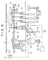
- FIG. 8 shows a vertical section of an apparatus used therein.
- An adjuster device for adjusting a discharge rate of a tracer gas 7 is composed of a control device 20, a computer 23 connecting to the control device 20 and storing weather data of an actual location, a flow rate control device 28 connecting to the control device 20 via a connecting wire 25, a flow rate meter 26 with a transmitter disposed on a tracer gas pipe 29 for leading the tracer gas 7 from the tracer gas bomb 19 to a discharge pipe 5a, and an electromagnetic flow rate control valve 27.
- the turntable 4 is rotated so as to obtain a desired wind direction by a signal from the control device 20. Simultaneously, a command regarding a gas discharge rate in compliance with the above-mentioned wind direction is transmitted to the flow rate control device 28, and a signal fed back from the flow rate meter 26 adjusts an open degree of the electromagnetic flow rate control valve 27 in order to maintain a predetermined relation between the wind direction and the gas flow rate.
- the wind direction and a tolerance of the exhaust gas can be realized before its construction, and in a factory for discharging the exhaust gas containing components which vary with works to be done, a relation between the wind direction and the works can be perceived, whereby environmental pollution can be prevented beforehand.
- an output of the air blower may be variable, and when the distribution state of the diffused tracer gas is tested, the tracer gas discharge pipe may be moved upward and downward in response to the wind direction or the wind velocity.
- the present invention can provide the gas diffusion testing apparatus in which the discharge rate of the tracer gas can be altered in compliance with the wind direction.
- a solid line in the wind rose represents the wind frequency and a dotted line the average wind velocity of each wind direction.
- 1% of the outer periphery of a turntable corresponds to 18 seconds.
- An air stream having a certain wind velocity is prepared in a wind tunnel, and the turntable 4 is rotated every 22.5° (360°/16) and is retained at a certain position for a time corresponding to the frequency of the wind rose in Fig. 9. For this period of time, the average wind velocity indicated by the dotted line is retained.
- the height AH varies with smoke discharge conditions (an upward discharge velocity and a discharge flow rate) and the wind velocity v as shown in Fig. 13.
- the Bosanquet formula is already put into practice.
- a rotation control device 20 is connected to a computer 23 in which weather data 30 of an actual location are stored, and a pulse motor 44 receives a signal from the rotation control device 20 through a connecting wire 43 and is driven thereby.
- a pinion 45 attached to an axial end portion of the pulse motor 44 is adapted to engage with a rack 46 mounted on a lower portion of a discharge pipe 5a extending through the center of a rotary shaft 4a under a turntable 4.
- a time distribution of a wind direction and a wind velocity for such a constitution is established from the weather data of the site as shown in Fig. 9, and the wind velocity is adjusted by controlling a rotation of the turntable 4 and a rotational frequency of the air blower 1a. Further, the height He of the tracer gas discharge opening 17 of the miniature chimney 5 is adjusted on the basis of a relation between the wind velocity and the discharge height shown in Fig. 13.
- the tracer gas 7 which is diffusing above a topography model 6 is taken in gas sampling tubes 41 from many gas suction openings 40, and gas concentrations are measured at several points at one time in order to examine the gas diffusion state.
- the time distribution of the wind direction and the wind velocity corresponding to the actual weather conditions of the site can be reproduced on a laboratory scale, and the accurate exhaust gas diffusion state can be realized by properly simulating the discharge height of the tracer gas.
- a discharge rate of the tracer gas may be controlled in compliance with the rotation angle of the turntable and/or the wind velocity.
- the present invention can provide the apparatus for testing the gas diffusion in which the height of the tracer gas discharge pipe can be adjusted in response to the wind velocity.
Landscapes
- Physics & Mathematics (AREA)
- General Physics & Mathematics (AREA)
- Engineering & Computer Science (AREA)
- Mathematical Optimization (AREA)
- Computational Mathematics (AREA)
- Mathematical Analysis (AREA)
- Algebra (AREA)
- Mathematical Physics (AREA)
- Pure & Applied Mathematics (AREA)
- Business, Economics & Management (AREA)
- Fluid Mechanics (AREA)
- Educational Administration (AREA)
- Educational Technology (AREA)
- Theoretical Computer Science (AREA)
- Aerodynamic Tests, Hydrodynamic Tests, Wind Tunnels, And Water Tanks (AREA)
Claims (5)
Applications Claiming Priority (10)
| Application Number | Priority Date | Filing Date | Title |
|---|---|---|---|
| JP25626184A JPS61133831A (ja) | 1984-12-04 | 1984-12-04 | ガス拡散試験方法 |
| JP256261/84 | 1984-12-04 | ||
| JP185936/84U | 1984-12-07 | ||
| JP18593684U JPS61102844U (de) | 1984-12-07 | 1984-12-07 | |
| JP31302/85 | 1985-02-19 | ||
| JP2243385U JPS61139455U (de) | 1985-02-19 | 1985-02-19 | |
| JP3130285A JPS61189430A (ja) | 1985-02-19 | 1985-02-19 | ガス拡散試験装置 |
| JP22433/85U | 1985-02-19 | ||
| JP71483/85 | 1985-04-04 | ||
| JP7148385A JPS61230040A (ja) | 1985-04-04 | 1985-04-04 | ガス拡散試験方法 |
Publications (2)
| Publication Number | Publication Date |
|---|---|
| EP0184545A1 EP0184545A1 (de) | 1986-06-11 |
| EP0184545B1 true EP0184545B1 (de) | 1989-04-05 |
Family
ID=27520458
Family Applications (1)
| Application Number | Title | Priority Date | Filing Date |
|---|---|---|---|
| EP85730159A Expired EP0184545B1 (de) | 1984-12-04 | 1985-12-03 | Verfahren und Vorrichtung zum Analysieren von Gasdiffusion |
Country Status (2)
| Country | Link |
|---|---|
| US (1) | US4646564A (de) |
| EP (1) | EP0184545B1 (de) |
Families Citing this family (12)
| Publication number | Priority date | Publication date | Assignee | Title |
|---|---|---|---|---|
| US4817039A (en) * | 1986-02-27 | 1989-03-28 | Fwg Associates, Inc. | Atmospheric controlled video simulation system |
| US5128881A (en) * | 1988-09-09 | 1992-07-07 | Saum Enterprises, Inc. | Means and methods for predicting hold time in enclosures equipped with a total flooding fire extinguishing system |
| US4896532A (en) * | 1988-11-09 | 1990-01-30 | Thermal Surveys, Inc. | Method of detecting turbulence in laminar air flow |
| US5127264A (en) * | 1991-05-20 | 1992-07-07 | Thermal Surveys, Inc. | Methods of infrared visualization of air flow |
| WO2011068910A2 (en) * | 2009-12-02 | 2011-06-09 | Air Dynamics Industrial Systems Corporation | Sand and dust environmental testing system |
| US10520423B2 (en) | 2009-12-02 | 2019-12-31 | Air Dynamics Industrial Systems Corporation | Modular sand and dust environmental testing system |
| AP2014008038A0 (en) * | 2012-07-31 | 2014-10-31 | Jgc Corp | Weather predicting method, weather predicting apparatus, and air utilizing apparatus |
| CN106017857B (zh) * | 2016-05-26 | 2017-07-11 | 中国人民解放军63820部队吸气式高超声速技术研究中心 | 吸气式高超声速飞行器分段部件气动力的测量方法 |
| CN108106811B (zh) * | 2017-12-20 | 2019-11-26 | 长沙理工大学 | 风洞试验污染物产生系统及监测系统 |
| CN109712501B (zh) * | 2018-11-21 | 2024-02-02 | 浙江大学 | 一种地下交通转换通道火灾模拟实验平台 |
| CN114235638A (zh) * | 2021-12-03 | 2022-03-25 | 北京科技大学 | 一种气体扩散模拟实验设备 |
| CN115100929B (zh) * | 2022-07-07 | 2023-10-27 | 淮阴工学院 | 一种物理实验的空气膨胀教学演示设备 |
Family Cites Families (3)
| Publication number | Priority date | Publication date | Assignee | Title |
|---|---|---|---|---|
| DE661286C (de) * | 1935-06-29 | 1938-06-15 | Provencale De Const Aeronautiq | Verfahren und Vorrichtung zur Veranschaulichung von Gasstroemungen |
| JPS57206844A (en) * | 1981-06-15 | 1982-12-18 | Mitsubishi Heavy Ind Ltd | Method of gas-diffusion color test |
| JPS58105034A (ja) * | 1981-12-18 | 1983-06-22 | Mitsubishi Heavy Ind Ltd | 粒子状物質拡散模擬試験方法 |
-
1985
- 1985-11-21 US US06/801,132 patent/US4646564A/en not_active Expired - Fee Related
- 1985-12-03 EP EP85730159A patent/EP0184545B1/de not_active Expired
Also Published As
| Publication number | Publication date |
|---|---|
| US4646564A (en) | 1987-03-03 |
| EP0184545A1 (de) | 1986-06-11 |
Similar Documents
| Publication | Publication Date | Title |
|---|---|---|
| EP0184545B1 (de) | Verfahren und Vorrichtung zum Analysieren von Gasdiffusion | |
| Borges et al. | Shelter effect on a row of coal piles to prevent wind erosion | |
| CN102818691A (zh) | 超大型冷却塔模拟试验装置及特性测试方法 | |
| US5807113A (en) | Method and apparatus for training in the detection of nuclear, biological and chemical (NBC) contamination | |
| Scheutz et al. | Validation and demonstration of a drone-based method for quantifying fugitive methane emissions | |
| CN107560821B (zh) | 一种研究沿海周边污染物扩散的风洞及其工作方法 | |
| US4817039A (en) | Atmospheric controlled video simulation system | |
| CN117571232A (zh) | 模拟海上平台有害气体泄漏扩散检测的试验装置 | |
| CN116698673A (zh) | 一种基于环境信息的危险气体泄漏三维扩散动态模拟方法 | |
| Cermak et al. | Physical modeling of urban air-pollutant transport | |
| JPS61110024A (ja) | 拡散風洞実験における風向制御方法 | |
| Obasaju et al. | Simulation of pollution dispersion using small scale physical models-an assessment of scaling options | |
| WO2024141721A1 (en) | Method and system for measuring emission rate of airborne emission species | |
| Etheridge | Modelling of air pollution in single-and multi-cell buildings | |
| JPS61230040A (ja) | ガス拡散試験方法 | |
| JPS61133831A (ja) | ガス拡散試験方法 | |
| JPS6352689B2 (de) | ||
| JPS60151539A (ja) | 煙拡散模型試験方法 | |
| JPS61189430A (ja) | ガス拡散試験装置 | |
| JP3129372B2 (ja) | 風路壁遮蔽装置 | |
| JPS636433A (ja) | ガス拡散試験方法 | |
| Alessio et al. | A laboratory model of wake-affected stack's emissions | |
| Cermak et al. | Wind-tunnel study of chimney downwash at the BL England Station of the Atlantic City Electric Company: report | |
| Petersen et al. | Evaluation of AERMOD/PRIME for two sites with unusual structures | |
| Petersen et al. | Effect of a Nearby Hill on Good Engineering Practice Stack Height |
Legal Events
| Date | Code | Title | Description |
|---|---|---|---|
| PUAI | Public reference made under article 153(3) epc to a published international application that has entered the european phase |
Free format text: ORIGINAL CODE: 0009012 |
|
| AK | Designated contracting states |
Kind code of ref document: A1 Designated state(s): CH FR GB LI NL |
|
| 17P | Request for examination filed |
Effective date: 19860606 |
|
| 17Q | First examination report despatched |
Effective date: 19870205 |
|
| GRAA | (expected) grant |
Free format text: ORIGINAL CODE: 0009210 |
|
| AK | Designated contracting states |
Kind code of ref document: B1 Designated state(s): CH FR GB LI NL |
|
| ET | Fr: translation filed | ||
| PLBE | No opposition filed within time limit |
Free format text: ORIGINAL CODE: 0009261 |
|
| STAA | Information on the status of an ep patent application or granted ep patent |
Free format text: STATUS: NO OPPOSITION FILED WITHIN TIME LIMIT |
|
| 26N | No opposition filed | ||
| PGFP | Annual fee paid to national office [announced via postgrant information from national office to epo] |
Ref country code: FR Payment date: 19921209 Year of fee payment: 8 |
|
| PGFP | Annual fee paid to national office [announced via postgrant information from national office to epo] |
Ref country code: CH Payment date: 19921214 Year of fee payment: 8 |
|
| PGFP | Annual fee paid to national office [announced via postgrant information from national office to epo] |
Ref country code: NL Payment date: 19921231 Year of fee payment: 8 |
|
| PGFP | Annual fee paid to national office [announced via postgrant information from national office to epo] |
Ref country code: GB Payment date: 19931123 Year of fee payment: 9 |
|
| PG25 | Lapsed in a contracting state [announced via postgrant information from national office to epo] |
Ref country code: LI Effective date: 19931231 Ref country code: CH Effective date: 19931231 |
|
| PG25 | Lapsed in a contracting state [announced via postgrant information from national office to epo] |
Ref country code: NL Effective date: 19940701 |
|
| NLV4 | Nl: lapsed or anulled due to non-payment of the annual fee | ||
| PG25 | Lapsed in a contracting state [announced via postgrant information from national office to epo] |
Ref country code: FR Effective date: 19940831 |
|
| REG | Reference to a national code |
Ref country code: CH Ref legal event code: PL |
|
| REG | Reference to a national code |
Ref country code: FR Ref legal event code: ST |
|
| PG25 | Lapsed in a contracting state [announced via postgrant information from national office to epo] |
Ref country code: GB Effective date: 19941203 |
|
| GBPC | Gb: european patent ceased through non-payment of renewal fee |
Effective date: 19941203 |