EP0184570A2 - Method and apparatus for producing a concrete or similar pile in the ground by using a tube of flexible material shielded by a protecting device, preferably a mandrel - Google Patents
Method and apparatus for producing a concrete or similar pile in the ground by using a tube of flexible material shielded by a protecting device, preferably a mandrel Download PDFInfo
- Publication number
- EP0184570A2 EP0184570A2 EP85870162A EP85870162A EP0184570A2 EP 0184570 A2 EP0184570 A2 EP 0184570A2 EP 85870162 A EP85870162 A EP 85870162A EP 85870162 A EP85870162 A EP 85870162A EP 0184570 A2 EP0184570 A2 EP 0184570A2
- Authority
- EP
- European Patent Office
- Prior art keywords
- tube
- flexible
- spindle
- concrete
- pipe
- Prior art date
- Legal status (The legal status is an assumption and is not a legal conclusion. Google has not performed a legal analysis and makes no representation as to the accuracy of the status listed.)
- Withdrawn
Links
Images

Classifications
-
- E—FIXED CONSTRUCTIONS
- E02—HYDRAULIC ENGINEERING; FOUNDATIONS; SOIL SHIFTING
- E02D—FOUNDATIONS; EXCAVATIONS; EMBANKMENTS; UNDERGROUND OR UNDERWATER STRUCTURES
- E02D5/00—Bulkheads, piles, or other structural elements specially adapted to foundation engineering
- E02D5/22—Piles
- E02D5/34—Concrete or concrete-like piles cast in position ; Apparatus for making same
- E02D5/38—Concrete or concrete-like piles cast in position ; Apparatus for making same making by use of mould-pipes or other moulds
- E02D5/385—Concrete or concrete-like piles cast in position ; Apparatus for making same making by use of mould-pipes or other moulds with removal of the outer mould-pipes
Definitions
- the present invention essentially relates to a method and device for producing a pile, for example of concrete or similar material, in the ground using a hose made of flexible material protected by a protective device, preferably in the form of a time zone.
- the plastic pipe is rigidly stretched in a driving tube between the driving head and a support device located above said pipe.
- the plastic pipe After the jacking pipe, for example, has reached the required depth, the plastic pipe is filled with concrete in a pourable form. Concrete applies the plastic pipe to the inside wall of the jacking pipe.
- the plastic pipe When the jacking pipe is removed, the plastic pipe may be damaged by irregularities. tears in the wall of this tube.
- the present invention therefore aims to solve the new technical problem consisting in providing a method and a device for producing a pile, for example of concrete or similar material, in the ground, using a material pipe. plastic, so as to protect it effectively during driving and removal of the driving tube, in a relatively simple and inexpensive manner.
- the present invention solves this technical problem for the first time.
- the flexible pipe is stored on a cassette arranged inside the spindle.
- This flexible pipe can be arranged in the form of an accordion on said cassette.
- the plastic pipe being placed in the spindle during driving and during the first phase of withdrawal of the driving pipe can in no way be damaged.
- the plastic pipe is pulled, over an extra thickness dimensioned so that the pipe is rigidly stretched, without undergoing excessive stress.
- the flexible pipe separates from the spindle and is filled simultaneously, for example with fluid or liquid concrete or the like.
- This separation has the effect that the lower end of the jacking tube is slightly above the lower end of the spindle, so that the plastic pipe is not applied against the inner bottom edge of the jacking tube under the effect of concrete pressure.
- the plastic pipe is no longer pressed against the inner face of the driving tube, generally made of steel, over its entire height under the effect of the pressure of the concrete.
- This plastic pipe can be arranged over the entire length of the pile, for example, or only over part of it.
- the lower end of the plastic pipe is fixed to the driving head or the like by means of wires, cables or any other similar device.
- the plastic pipe tick is not present on the lower part of the pile, for example, so that liquid or fluid concrete can flow freely until contact with the surrounding soil, which allows a good bond between the concrete and the soil and thus avoid any harmful repercussions on the bearing capacity of the piles.
- the plastic pipe can also be arranged along the entire length of the pile.
- the present invention also relates to a device for producing a pile, for example of concrete or similar material, in the ground, comprising a sinking tube made of resistant material, relatively rigid or non-deformable, said sinking tube comprising inside a hose made of flexible, flexible material, for example plastic, intended to serve as a casing for concrete or the like to define the pile, rigidly stretched between the driving head and a support device, characterized in that the support device includes a protection device suspended inside the jacking tube protecting the flexible hose against contact with the jacking tube.
- the protection device comprises a spindle with double concentric walls radially spaced providing a space for the arrangement of the flexible pipe.
- the flexible hose is wound on a cassette arranged inside the spindle.
- the plastic pipe can be arranged over the entire length of the pile, for example, or only over part of it.
- the plastic pipe is not present on the lower part of the pile, for example, so that the fluid or liquid concrete or similar material can flow freely until contact with the surrounding soil, which makes it possible to obtain a good bond between the concrete and the ground and thus to avoid any harmful repercussion on the bearing power of the piles.
- the plastic pipe can also be arranged over the entire length of the pile.
- annular rubber flap is provided on the underside of the spindle.
- the length and arrangement of this bib can be adapted to the particular circumstances.
- this flap may even be totally lacking.
- this flap can be short and not very flexible and constitute, in this case, only a seal against screw concrete when the jacking pipe is filled with concrete. Under the effect of the concrete pressure, this flap is applied against the wall of the driving tube, at the time of the start of concrete pouring and therefore automatically ensures a good seal.
- the rubber flap can be longer, so that its underside has the possibility of expanding so that the rubber flap takes the shaped like a truncated cone.
- the rubber flap must have the characteristic that its lower face can reach a markedly greater diameter, while its upper face remains at the same diameter.
- the flap is preferably made for this purpose in strips of a pleated envelope, or in an expandable material.
- the flap Under the effect of pressure, for example liquid concrete flowing in the pipe or the sinking tube, the flap is pressed outwards when the concrete escapes from the interior of the spindle and is forced to take the shape of a truncated cone.
- the plastic pipe is separated from the spindle when the spindle is extracted plus the driving tube and over the flap expanded by the pressure of the concrete.
- the dimensions of the flap and the plastic pipe must be chosen so that the plastic pipe is slightly under tension when the spindle is extracted.
- the arrangement of the flexible plastic pipe, or plastic material, on a cassette is not necessary but is only an auxiliary means to speed up production.
- the plastic pipe is placed beforehand on the cassette and the cassette comprising the flexible pipe is introduced into the spindle between the two concentric radially spaced walls. Then, at the lower part of the barrel, there is a detachable ring, generally made of steel, by means of quick coupling means. Finally, the wires or cables connected to the lower end of the flexible pipe are fixed to the driving head.
- the spindle principle can also be applied in cases where the spindle is placed in the driving tube after the latter has been brought to the required depth at which it is sufficient for the lower end of the pipe to be flexible material is retained when extracting the spindle in a different manner than that described above.
- the spindle is generally designed so that the hose made of soft, flexible material, such as plastic, is optimally protected at all stages of operation, by means of a wall forming a hose. or buffer, preferably made of steel, disposed between the hose made of flexible flexible material and the inner wall of the driving tube.
- a device according to the invention for producing the pile for example made of concrete or the like, in the ground, comprises a driving tube 1 made of resistant material, relatively rigid or non-deformable.
- This driving tube 1 includes inside a hose 2 made of flexible, flexible material, for example plastic, intended to serve as a concrete casing or the like to define the pile.
- This pipe 2 is rigidly tensioned between the driving head (not shown in FIG. 1 but clearly visible in FIGS. 2 to 2c), represented by the general reference number 4 and a support device represented by the general reference number 6.
- this device is characterized in that the support device comprises a protection device represented by the general reference number 8 suspended inside the driving tube using suspension cables 9 connected for example to a classic winch.
- This protection device 8 is designed so as to protect the flexible pipe against contact with the internal wall of the driving tube 1.
- the protection device 8 comprises a spindle 10 with double walls 12, 14, respectively internal and external radially spaced, providing a space 16 for the arrangement of the flexible pipe 2.
- the flexible pipe 2 is stored on a cassette 18 disposed inside the spindle 10, that is to say in the space 16 defined between the concentric walls 12, 14.
- the concentric walls 12, 14 are fixed at the upper part of the spindle 10 to a ring 20 of mechanically resistant material, relatively rigid or non-deformable, for example steel.
- This ring has a conical profile 22, the large base of which receives the walls 12, 14.
- the external wall 20 of this ring is provided with sealing means 24 sealing between the ring 20 and the driving tube 1.
- another ring 26 detachable mounted by means of quick coupling to the internal wall 12.
- This ring 26 has on its outer face a conical profile 28 radially increasing in the direction of the driving head 4
- a flap 30, is attached to this ring 26 a flap 30, generally made of rubber.
- This flap 30 is preferably made in the form of strips of a pleated envelope, or else in an expandable material. This flap can for example be made of rubber, natural or synthetic.
- the outer wall 14 is shorter and provides an opening normally closed by an elastic annular closure means 36 such as a flap which can be made of rubber.
- the dimension of the flap 30 varies according to whether the diameter of the flexible flexible pipe 2 differs little or strongly from the inside diameter of the driving tube 1.
- the flap 30 is short and not very flexible, and in this case simply provides only a seal against the concrete when the tube 1 is filled with concrete.
- the flap 30 can be longer so that its underside has the possibility of expanding so that this flap takes the form of a truncated cone.
- the flexible material pipe is fixed at its lower end to the driving head 4 by means of cables or wires 32.
- the spindle 10 has a through axial opening 34 which will allow the free passage of fluid or liquid concrete or any similar material in the direction of the driving head.
- FIG. 2a represents the position of the driving tube 1 and the spindle 10 at the end of the driving step when the driving tube reaches a determined depth.
- the inside of the driving tube 1, therefore of the spindle 10, is filled with fluid or liquid concrete 42 or any other similar material, up to the driving head 4.
- the driving tube 1 is raised slightly while the spindle 10 remains at the same depth.
- the driving tube 1 therefore slides along the spindle 10 and the concrete flows through the spindle during this extraction operation up to the head 4 remaining in place.
- the driving tube 1 is raised enough so that the lower end of the latter is slightly above the lower end of the spindle 10, that is to say in practice above the lower end of the outer wall 14 of the spindle 10 so as not to hinder the passage of the flexible pipe 2, as clearly visible in FIG. 2a.
- FIG. 2b represents an intermediate position showing the spindle partially raised to an intermediate depth.
- the flexible pipe 2 is thus extracted from the spindle 10 because the lower end of the flexible pipe 2 is fixed to the driving head 4 which remains in place, by means of cables or wires 32.
- the flexible pipe ⁇ 2 Since the flexible pipe ⁇ 2 is pulled by being guided by the conical surface 28 of the ring 26 and also by the swelling of the expandable flap 30 under the effect of the pressure of the concrete, this flexible pipe 2 is rigidly stretched, without be overloaded. Furthermore, during the extraction of the driving tube and the spindle 10, the flexible pipe 2 not only separates from the spindle but also simultaneously fills with fluid or liquid concrete or any similar material.
- the flexible pipe 2 is not applied against the inner lower edge of the tube jacking 1 under the effect of concrete pressure and does not risk being damaged.
- the flexible pipe 2 is no longer pressed against the inner face of the driving tube 1 over its entire height under the effect of the pressure of the concrete.
- the flexible pipe 2 can be arranged over the entire length of the pile, for example, or only over part of it.
- the flexible pipe 2 is not present on the lower part of the pile, for example, so that the liquid concrete can flow freely until contact with the surrounding soil, thus making it possible to obtain a good attachment between the concrete 42 and the soil 40 and also avoiding any harmful repercussions on the bearing power of the piles.
- the flexible pipe 2 can also be arranged over the entire length of the pile.
- the sealing devices 24, 38 which are preferably arranged in several places between the spindle 10 and the inner face of the driving tube 1, it is prevented that grains of gravel, for example, do not enter this cavity and that the spindle 10 does not block in the driving tube 1.
- the flexible pipe 2 makes it possible to protect the concrete against the aggressive agents of the soil and avoids an overconsumption of the concrete in soft soils by preventing the formation of huge balls or blisters.
Landscapes
- Engineering & Computer Science (AREA)
- Structural Engineering (AREA)
- Life Sciences & Earth Sciences (AREA)
- General Life Sciences & Earth Sciences (AREA)
- Mining & Mineral Resources (AREA)
- Paleontology (AREA)
- Civil Engineering (AREA)
- General Engineering & Computer Science (AREA)
- Piles And Underground Anchors (AREA)
Abstract
Description
La présente invention concerne essentiellement un procédé et dispositif de réalisation d'un pieu, par exemple en béton ou matériau analogue, dans le sol avec utilisation d'un tuyau en matière flexible protégé par un dispositif de protection, de préférence sous forme d'un fuseau.The present invention essentially relates to a method and device for producing a pile, for example of concrete or similar material, in the ground using a hose made of flexible material protected by a protective device, preferably in the form of a time zone.
Suivant une méthode actuellement connue pour le placement d'un tuyau en matière plastique servant d'enveloppe, par exemple pour du béton, au cours de la réalisation de pieux de fondation, le tuyau en matière plastique est tendu rigidement dans un tube de fonçage entre la tête de fonçage et un dispositif de support située au-dessus dudit tuyau.According to a currently known method for placing a plastic pipe serving as an envelope, for example for concrete, during the production of foundation piles, the plastic pipe is rigidly stretched in a driving tube between the driving head and a support device located above said pipe.
Après que le tube de fonçage, par exemple, soit arrivé à la profondeur requise, le tuyau en matière plastique est rempli de béton sous une forme coulable. Le béton applique le tuyau en matière plastique centre la paroi intérieure du tube de fonçage.After the jacking pipe, for example, has reached the required depth, the plastic pipe is filled with concrete in a pourable form. Concrete applies the plastic pipe to the inside wall of the jacking pipe.
Au moment où le tube de fonçage est retiré, le tuyau en matière plastique peut-être endommagé par des irrégularités de la paroi de ce tube.When the jacking pipe is removed, the plastic pipe may be damaged by irregularities. tears in the wall of this tube.
D'autre part, au cours de l'extraction du tube de fonçage, le tuyau en matière plastique est pressé fortement contre l'extrémité inférieure du tube de fonçage, sous l'effet de la pression du béton, ce qui peut provoquer également des dommages au tube en matière plastique à cet endroit.On the other hand, during the extraction of the jacking tube, the plastic pipe is pressed strongly against the lower end of the jacking tube, under the effect of the pressure of the concrete, which can also cause damage to the plastic tube there.
D'autre part, on a fait également des essais avec un tube en matière plastique tendu au bord extérieur du tube de fonçage, par exemple, mais l'enveloppe en matière plastique peut également être déchirée alors au cours du fonçage du tube, par suite des forces de frottement importantes provoquées par l'opération de fonçage.On the other hand, tests have also been made with a plastic tube stretched at the outer edge of the driving tube, for example, but the plastic casing can also be torn off while sinking the tube, consequently significant friction forces caused by the driving operation.
La présente invention a donc pour but de résoudre le nouveau problème technique consistant en la fourniture d'un procédé et d'un dispositif de réalisation d'un pieu, par exemple en béton ou matériau analogue, dans le sol, utilisant un tuyau en matière plastique, de manière à le protéger efficacement pendant le fonçage et le retrait du tube de fonçage, de manière relativement simple et peu coûteuse.The present invention therefore aims to solve the new technical problem consisting in providing a method and a device for producing a pile, for example of concrete or similar material, in the ground, using a material pipe. plastic, so as to protect it effectively during driving and removal of the driving tube, in a relatively simple and inexpensive manner.
Simultanément, on doit également éviter que le tuyau en matière plastique ne soit appuyé contre la face intérieure du tube de fonçage, sous l'effet de la pression du béton fluide ou liquide, ce qui pourrait provoquer des dommages au tuyau en matière plastique au moment de l'extraction du tube de fonçage.At the same time, it must also be avoided that the plastic pipe is pressed against the inner face of the jacking pipe, under the effect of the pressure of the fluid or liquid concrete, which could cause damage to the plastic pipe at the moment. the extraction of the driving tube.
La présente invention permet de résoudre ce problème technique pour la première fois.The present invention solves this technical problem for the first time.
La présente invention, selon un premier aspect, fournit donc un procédé de réalisation d'un pieu, par exemple en béton, dans le sol, comprenant les étapes suivantes :
- - le fonçage dans le sol, à une profondeur déterminée, d'un tube de fonçage en matière résistante, relativement rigide ou non déformable, comportant une tête de fonçage détachable, ledit tube de fonçage comprenant à l'intérieur un tuyau flexible en matière souple, par exemple en matière plastique, destiné à servir d'enveloppe au béton ou analogue pour définir le pieu, tendu rigidement entre la tête de fonçage et un dispositif de support,
- - le remplissage de l'intérieur dudit tube et dudit tuyau avec du béton fluide ou liquide, ou analogue,
- - la séparation du tube de fonçage de ladite tête de fonçage, et
- - le retrait du tube de fonçage en laissant ledit tuyau dans le sol, de manière à ce qu'il forme alors une enveloppe pour le béton,
caractérisé en ce qu'on dispose le tuyau flexible, à l'intérieur d'un dispositif de protection suspendu à l'intérieur du tube de fonçage, on réalise ensuite le retrait du tube de fonçage en deux phases, dans la première phase, ce retrait est réalisé en maintenant le dispositif de protection en place à la même profondeur jusqu'à ce que l'extrémité inférieure du tube de fonçage se trouve légèrement au-dessus de l'extrémité inférieure du dispositif de protection, ensuite dans une deuxième phase on retire simultanément le tube de fonçage et le dispositif de protection en provoquant l'extraction du tuyau flexible du dispositif de protection et son remplissage simultané avec le béton fluide ou analogue. Aussi, le procédé est caractérisé en ce que le dispositif de protection comprend un fuseau à double parois concentriques radialement espacées en ménageant un espace pour la disposition du tuyau flexible.The present invention, according to a first aspect, therefore provides a method of producing a pile, for example of concrete, in the ground, comprising the following steps:
- - sinking into the ground, to a determined depth, a sinking tube made of resistant material, relatively rigid or non-deformable, comprising a detachable sinking head, said sinking tube comprising inside a flexible hose made of flexible material , for example made of plastic, intended to serve as an envelope for concrete or the like to define the pile, rigidly stretched between the driving head and a support device,
- - filling the interior of said tube and said pipe with fluid or liquid concrete, or the like,
- - the separation of the driving tube from said driving head, and
- - the withdrawal of the jacking tube leaving the said pipe in the ground, so that it then forms an envelope for the concrete,
characterized in that the flexible hose is placed inside a protection device suspended inside the driving tube, the withdrawal of the driving tube is then carried out in two phases, in the first phase, this removal is achieved by keeping the protection device in place at the same depth until the lower end of the jacking tube is slightly above the lower end of the protection device, then in a second phase simultaneously withdraws the sinking tube and the protection device by causing the flexible pipe to be extracted from the protection device and its simultaneous filling with fluid concrete or the like. Also, the method is characterized in that the protection device comprises a spindle with double concentric walls radially spaced, leaving a space for the arrangement of the flexible pipe.
Selon une caractéristique préférée, le tuyau flexible est stocké sur une cassette disposée à l'intérieur du fuseau. Ce tuyau flexible peut être disposé en forme d'accordéon sur ladite cassette.According to a preferred characteristic, the flexible pipe is stored on a cassette arranged inside the spindle. This flexible pipe can be arranged in the form of an accordion on said cassette.
Ainsi, le tuyau en matière plastique étant disposé dans le fuseau pendant le fonçage et pendant la première phase de retrait du tube de fonçage, ne peut être en aucun cas endommagé. De préférence, le tuyau en matière plastique est tiré, par dessus une surépaisseur dimensionnée de manière à ce que le tuyau soit tendu rigidement, sans subir de sollicitation excessive.Thus, the plastic pipe being placed in the spindle during driving and during the first phase of withdrawal of the driving pipe, can in no way be damaged. Preferably, the plastic pipe is pulled, over an extra thickness dimensioned so that the pipe is rigidly stretched, without undergoing excessive stress.
Ainsi, pendant l'extraction du tube de fonçage et du fuseau, le tuyau flexible se sépare du fuseau et se remplit simultanément, par exemple avec du béton fluide ou liquide ou analogue.Thus, during the extraction of the driving tube and the spindle, the flexible pipe separates from the spindle and is filled simultaneously, for example with fluid or liquid concrete or the like.
Cette séparation a pour effet que l'extrémité inférieure du tube de fonçage se trouve légèrement au-dessus de l'extrémité inférieure du fuseau, si bien que le tuyau en matière plastique n'est pas appliqué contre le bord inférieur intérieur du tube de fonçage sous l'effet de la pression du béton.This separation has the effect that the lower end of the jacking tube is slightly above the lower end of the spindle, so that the plastic pipe is not applied against the inner bottom edge of the jacking tube under the effect of concrete pressure.
De plus, le tuyau en matière plastique n'est plus pressé contre la face intérieure du tube de fonçage, en général réalisé en acier, sur toute sa hauteur sous l'effet de la pression du béton.In addition, the plastic pipe is no longer pressed against the inner face of the driving tube, generally made of steel, over its entire height under the effect of the pressure of the concrete.
Ce tuyau en matière plastique peut être disposé sur toute la longueur du pieu, par exemple, ou seulement sur une partie de celle-ci.This plastic pipe can be arranged over the entire length of the pile, for example, or only over part of it.
Selon un mode de réalisation particulier:,.l'extrémité inférieure du tuyau en matière plastique est fixée à la tête de fonçage ou analogue au moyen de fils, de câbles ou tout autre dispositif similaire.According to a particular embodiment: the lower end of the plastic pipe is fixed to the driving head or the like by means of wires, cables or any other similar device.
Ainsi, en faisant varier la longueur des fils ou des câbles situés dans la partie inférieure du tuyau en matière plastique, on peut obtenir que le tuyau en matière plastique ne soit pas présent sur la partie inférieure du pieu, par exemple, si bien que le béton liquide ou fluide puisse s'écouler librement jusqu'au contact avec le sol environnant, ce qui permet d'obtenir un bon accrochage entre le béton et le sol et d'éviter ainsi toute répercussion néfaste sur la force portante des pieux.Thus, by varying the length of the wires or cables located in the lower part of the plastic pipe, it is possible to obtain that the plastic pipe tick is not present on the lower part of the pile, for example, so that liquid or fluid concrete can flow freely until contact with the surrounding soil, which allows a good bond between the concrete and the soil and thus avoid any harmful repercussions on the bearing capacity of the piles.
Le tuyau en matière plastique peut également être disposé sur toute la longueur du pieu.The plastic pipe can also be arranged along the entire length of the pile.
La présente invention concerne également un dispositif de réalisation d'un pieu, par exemple en béton ou matériau analogue, dans le sol, comprenant un tube de fonçage en matière résistante, relativement rigide ou non déformable, ledit tube de fonçage comprenant à l'intérieur un tuyau en matière souple, flexible, par exemple en matière plastique, destiné à servir d'enveloppe du béton ou analogue pour définir le pieu, tendu rigidement entre la tête de fonçage et un dispositif de support, caractérisé en ce que le dispositif de support comprend un dispositif de protection suspendu à l'intérieur du tube de fonçage protégeant le tuyau flexible contre un contact avec le tube de fonçage.The present invention also relates to a device for producing a pile, for example of concrete or similar material, in the ground, comprising a sinking tube made of resistant material, relatively rigid or non-deformable, said sinking tube comprising inside a hose made of flexible, flexible material, for example plastic, intended to serve as a casing for concrete or the like to define the pile, rigidly stretched between the driving head and a support device, characterized in that the support device includes a protection device suspended inside the jacking tube protecting the flexible hose against contact with the jacking tube.
Selon un mode de réalisation préféré de l'invention, le dispositif de protection comprend un fuseau à double parois concentriques radialement espacées aménageant un espace pour la disposition du tuyau flexible.According to a preferred embodiment of the invention, the protection device comprises a spindle with double concentric walls radially spaced providing a space for the arrangement of the flexible pipe.
De préférence, le tuyau flexible est enroulé sur une cassette disposée à l'intérieur du fuseau.Preferably, the flexible hose is wound on a cassette arranged inside the spindle.
Comme indiqué précédemment, le tuyau en matière plastique peut être disposé sur toute la longueur du pieu, par exemple, ou seulement sur une partie de celle-ci. D'autre part, en faisant varier la longueur des câbles ou des fils situés dans la partie inférieure du tuyau en matière plastique, on peut obtenir que le tuyau en matière plastique ne soit pas présent sur la partie inférieure du pieu, par exemple, si bien que le béton fluide ou liquide ou matériau analogue puisse s'écouler librement jusqu'au contact avec le sol environnant, ce qui permet d'obtenir un bon accrochage entre le béton et le sol et d'éviter ainsi toute répercussion néfaste sur la force portante des pieux.As indicated above, the plastic pipe can be arranged over the entire length of the pile, for example, or only over part of it. On the other hand, by varying the length of the cables or wires located in the lower part of the material pipe plastic, it is possible to obtain that the plastic pipe is not present on the lower part of the pile, for example, so that the fluid or liquid concrete or similar material can flow freely until contact with the surrounding soil, which makes it possible to obtain a good bond between the concrete and the ground and thus to avoid any harmful repercussion on the bearing power of the piles.
D'autre part, le tuyau en matière plastique peut également être disposé sur toute la longueur du pieu.On the other hand, the plastic pipe can also be arranged over the entire length of the pile.
D'autre part, selon un mode de réalisation particulier, on prévoit sur la face inférieure du fuseau une bavette annulaire en caoutchouc. La longueur et la disposition de cette bavette peuvent être adaptées aux circonstances particulières.Furthermore, according to a particular embodiment, an annular rubber flap is provided on the underside of the spindle. The length and arrangement of this bib can be adapted to the particular circumstances.
Dans certains cas, cette bavette peut même faire totalement défaut. C'est ainsi qu'au cas où le diamètre du tuyau en matière plastique ne diffère pas fortement du diamètre intérieur du tube de fonçage, cette bavette peut être courte et peu flexible et constituer, dans ce cas, uniquement une étanchéité vis-à-vis du béton au moment où le tube de fonçage est rempli de béton. Sous l'effet de la pression du béton, cette bavette est appliquée contre la paroi du tube de fonçage, au moment du début de la coulée du béton et assure donc automatiquement une bonne étanchéité.In some cases, this flap may even be totally lacking. Thus in the case where the diameter of the plastic pipe does not differ greatly from the internal diameter of the jacking tube, this flap can be short and not very flexible and constitute, in this case, only a seal against screw concrete when the jacking pipe is filled with concrete. Under the effect of the concrete pressure, this flap is applied against the wall of the driving tube, at the time of the start of concrete pouring and therefore automatically ensures a good seal.
Si le diamètre du tuyau en matière plastique est nettement supérieur au diamètre inférieur du tube de fonçage, la bavette en caoutchouc peut être plus longue, de manière à ce que sa face inférieure ait la possibilité de se dilater afin que la bavette en caoutchouc prenne la forme d'un cône tronqué.If the diameter of the plastic pipe is significantly larger than the lower diameter of the driving tube, the rubber flap can be longer, so that its underside has the possibility of expanding so that the rubber flap takes the shaped like a truncated cone.
A cet effet, la bavette en caoutchouc doit avoir pour caractéristique que sa face inférieure puisse atteindre un diamètre nettement supérieur, tandis que sa face supérieure reste au même diamètre.To this end, the rubber flap must have the characteristic that its lower face can reach a markedly greater diameter, while its upper face remains at the same diameter.
La bavette est réalisée de préférence à cet effet en lamelles d'une enveloppe plissée, ou bien en un matériau expansible.The flap is preferably made for this purpose in strips of a pleated envelope, or in an expandable material.
Sous l'effet de la pression, par exemple du béton liquide s'écoulant dans le tuyau ou le tube de fonçage, la bavette est pressée vers l'extérieur lorsque le béton s'échappe de l'intérieur du fuseau et est obligé de prendre la forme d'un cône tronqué.Under the effect of pressure, for example liquid concrete flowing in the pipe or the sinking tube, the flap is pressed outwards when the concrete escapes from the interior of the spindle and is forced to take the shape of a truncated cone.
Le tuyau en matière plastique est séparé du fuseau au moment de l'extraction du fuseau plus le tube de fonçage et par dessus la bavette expansée par la pression du béton. Les dimensions de la bavette et du tuyau en matière plastique doivent être choisies de manière à ce que le tube en matière plastique soit légèrement sous tension à l'extraction du fuseau.The plastic pipe is separated from the spindle when the spindle is extracted plus the driving tube and over the flap expanded by the pressure of the concrete. The dimensions of the flap and the plastic pipe must be chosen so that the plastic pipe is slightly under tension when the spindle is extracted.
La disposition du tuyau en matière plastique flexible, ou en matière plastique, sur une cassette n'est pas nécessaire mais constitue seulement un moyen auxiliaire pour accélérer la production.The arrangement of the flexible plastic pipe, or plastic material, on a cassette is not necessary but is only an auxiliary means to speed up production.
En règle générale, on dispose le tuyau en matière plastique au préalable sur la cassette et la cassette comportant le tuyau flexible est introduite dans le fuseau entre les deux parois concentriques radialement espacées. Ensuite, on dispose à la partie inférieure dufuseau,un anneau détachable, en général en acier, à l'aide de moyens d'accouplement rapide. Enfin, les fils ou câbles reliés à l'extrémité inférieure du tuyau flexible sont fixés à la tête de fonçage.As a general rule, the plastic pipe is placed beforehand on the cassette and the cassette comprising the flexible pipe is introduced into the spindle between the two concentric radially spaced walls. Then, at the lower part of the barrel, there is a detachable ring, generally made of steel, by means of quick coupling means. Finally, the wires or cables connected to the lower end of the flexible pipe are fixed to the driving head.
Selon une variante de réalisation, le principe du fuseau peut également être appliqué dans les cas où le fuseau est disposé dans le tube de fonçage après que celui-ci ait été amené à la profondeur requise auquel il suffit que l'extrémité inférieure du tuyau en matière flexible soit retenue au moment de l'extraction du fuseau d'une autre manière que celle décrite précédemment.According to an alternative embodiment, the spindle principle can also be applied in cases where the spindle is placed in the driving tube after the latter has been brought to the required depth at which it is sufficient for the lower end of the pipe to be flexible material is retained when extracting the spindle in a different manner than that described above.
Le fuseau est conçu de manière générale de manière à ce que le tuyau en matière souple, flexible, telle qu'une matière plastique, soit protégé d'une manière optimale à toutes les phases d'opération, au moyen d'une paroi formant tuyau ou tampon, de préférence en acier, disposée entre le tuyau en matière souple flexible et la paroi intérieure du tube de fonçage.The spindle is generally designed so that the hose made of soft, flexible material, such as plastic, is optimally protected at all stages of operation, by means of a wall forming a hose. or buffer, preferably made of steel, disposed between the hose made of flexible flexible material and the inner wall of the driving tube.
On peut naturellement prévoir des dispositifs d'étanchéité en plusieurs endroits entre le fuseau et la face intérieure du tube de fonçage afin d'empêcher que des grains de gravier, par exemple, ne pénètrent dans cette cavité et que le fuseau ne se bloque dans le tube de fonçage.It is naturally possible to provide sealing devices in several places between the spindle and the inner face of the driving tube in order to prevent grains of gravel, for example, from entering this cavity and the spindle from jamming in the jacking tube.
L'invention sera maintenant décrite plus en détail à l'aide des dessins annexés représentant un mode de réalisation actuellement préféré du dispositif selon l'invention, donné simplement à titre d'illustration et qui ne saurait donc en aucune façon limiter la portée de l'invention. Dans les dessins :
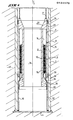
- - la figure 1 représente une coupe d'un tube de fonçage équipé du dispositif selon l'invention comprenant un fuseau suspendu à des câbles dans ce tube de fonçage, la coupe étant réalisée au niveau du dispositif selon l'invention; et
- - les figures 2a à 2c représentent les différentes phases du procédé.
- - Figure 1 shows a section through a sinking tube fitted with the device according to the invention comprising a spindle suspended from cables in this sinking tube, the section being made at the level of the device according to the invention; and
- - Figures 2a to 2c show the different phases of the process.
En référence à la figure 1, un dispositif selon l'invention pour la réalisation du pieu, par exemple en béton ou analogue, dans le sol, comprend un tube de fonçage 1 en matière résistante, relativement rigide ou non déformable. Ce tube de fonçage 1 comprend à l'intérieur un tuyau 2 en matière souple, flexible, par exemple en matière plastique, destiné à servir d'enveloppe du béton ou analogue pour définir le pieu.With reference to FIG. 1, a device according to the invention for producing the pile, for example made of concrete or the like, in the ground, comprises a driving tube 1 made of resistant material, relatively rigid or non-deformable. This driving tube 1 includes inside a hose 2 made of flexible, flexible material, for example plastic, intended to serve as a concrete casing or the like to define the pile.
Ce tuyau 2 est tendu rigidement entre la tête de fonçage (non représenté à la figure 1 mais clairement visible aux figures 2à à 2c), représentée par le numéro de référence général 4 et un dispositif de support représenté par le numéro de référence général 6.This pipe 2 is rigidly tensioned between the driving head (not shown in FIG. 1 but clearly visible in FIGS. 2 to 2c), represented by the general reference number 4 and a support device represented by the general reference number 6.
Selon l'invention, ce dispositif est caractérisé en ce que le dispositif de support comprend un dispositif de protection représenté par le numéro de référence général 8 suspendu à l'intérieur du tube de fonçage à l'aide de câbles de suspension 9 reliés par exemple à un treuil classique.According to the invention, this device is characterized in that the support device comprises a protection device represented by the general reference number 8 suspended inside the driving tube using suspension cables 9 connected for example to a classic winch.
Ce dispositif de protection 8 est conçu de manière à protéger le tuyau flexible contre un contact avec la paroi interne du tube de fonçage 1.This protection device 8 is designed so as to protect the flexible pipe against contact with the internal wall of the driving tube 1.
Selon un mode de réalisation actuellement préféré de l'invention, le dispositif de protection 8 comprend un fuseau 10 à double parois 12, 14, respectivement interne et externe radialement espacées aménageant un espace 16 pour la disposition du tuyau flexible 2.According to a currently preferred embodiment of the invention, the protection device 8 comprises a
Selon une caractéristique préférée, le tuyau flexible 2 est stocké sur une cassette 18 disposée à l'intérieur du fuseau 10, c'est-à-dire dans l'espace 16 défini entre les parois concentriques 12, 14.According to a preferred characteristic, the flexible pipe 2 is stored on a
Les parois concentriques 12, 14 sont fixées à la partie supérieure du fuseau 10 à un anneau 20 en matière mécaniquement résistante, relativement rigide ou non déformable, par exemple en acier. Cet anneau présente un profil conique 22 dont la grande base reçoit les parois 12, 14. La paroi externe 20 de cet anneau est pourvue de moyens d'étanchéité 24 réalisant une étanchéité entre l'anneau 20 et le tube de fonçage 1. A la partie inférieure du fuseau 10, il est prévu un autre anneau 26 monté détachable par des moyens d'accouplement rapide à la paroi interne 12. Cet anneau 26 présente sur sa face externe un profil conique 28 radialement croissant en direction de la tête de fonçage 4. A cet anneau 26 est fixée une bavette 30, généralement réalisée en caoutchouc. Cette bavette 30 est de préférence réalisée sous la forme de lamelles d'une enveloppe plissée, ou bien en un matériau expansible. Cette bavette peut par exemple être réalisée en caoutchouc, naturel ou synthétique. La paroi externe 14 est plus courte et ménage une ouverture normalement fermée par un moyen de fermeture annulaire 36 élastique tel qu'une bavette qui peut être réalisée en caoutchouc.The
La dimension de la bavette 30 varie selon que le diamètre du tuyau souple flexible 2 diffère peu ou fortement du diamètre intérieur du tube de fonçage 1.The dimension of the
Dans le cas où la différence de diamètre est faible, la bavette 30 est courte et peu flexible, et n'assure dans ce cas simplement qu'une étanchéité vis-à-vis du béton au moment ou le tube 1 est rempli de béton. Dans le cas où la différence de diamètre est importante, la bavette 30 peut être plus longue de manière à ce que sa face inférieure ait la possibilité de se dilater afin que cette bavette prenne la forme d'un cône tronqué. D'autre part, il est important que les dimensions de la bavette 30 et du tuyau en matière souple flexible 2 soient choisies de manière à ce que le tuyau 2 en matière flexible soit légèrement sous tension après l'extraction hors du fuseau 10.In the case where the difference in diameter is small, the
Comme indiqué précédemment, le tuyau en matière flexible est fixé à son extrémité inférieure à la tête de fonçage 4 au moyen de câbles ou de fils 32.As indicated above, the flexible material pipe is fixed at its lower end to the driving head 4 by means of cables or
On peut observer ainsi que le fuseau 10 présente une ouverture axiale traversante 34 qui permettra le passage libre du béton fluide ou liquide ou toute matière analogue en direction de la tête de fonçage.It can thus be observed that the
On va maintenant décrire le procédé de réalisation d'un pieu avec ce dispositif selon l'invention, en référence aux figures 2a à 2c, dans le sol 40.We will now describe the process for producing a pile with this device according to the invention, with reference to FIGS. 2a to 2c, in the
La figure 2a représente la position du tube de fonçage 1 et du fuseau 10 à la fin de l'étape de fonçage lorsque le tube de fonçage atteint une profondeur déterminée. On réalise le remplissage de l'intérieur du tube de fonçage 1, donc du fuseau 10 avec du béton fluide ou liquide 42 ou tout autre matériau analogue, jusqu'à la tête de fonçage 4. Ensuite, en référence à la figure 2a, le tube de fonçage 1 est remonté légèrement pendant que le fuseau 10 reste à la même profondeur. Le tube de fonçage 1 glisse donc le long du fuseau 10 et le béton s'écoule à travers le fuseau pendant cette opération d'extraction jusqu'à la tête 4 restant en place.FIG. 2a represents the position of the driving tube 1 and the
Le tube de fonçage 1 est remonté suffisamment pour que l'extrémité inférieure de celui-ci se trouve légèrement au-dessus de l'extrémité inférieure du fuseau 10, c'est-à-dire en pratique au-dessus de l'extrémité inférieure de la paroi externe 14 du fuseau 10 de manière à ne pas gener le passage du tuyau flexible 2, comme clairement visible à le figure 2a.The driving tube 1 is raised enough so that the lower end of the latter is slightly above the lower end of the
Ensuite, et comme on le voit bien à la figure 2b, le tube de fonçage 1, et le fuseau 10 sont remontés simultanément. La figure 2b représente une position intermédiaire montrant le fuseau en partie remonté à une profondeur intermédiaire. Au fur et à mesure de ce mouvement, le tuyau flexible 2 est extrait ainsi du fuseau 10 car l'extrémité inférieure du tuyau flexible 2 est fixée à la tête de fonçage 4 qui reste en place, au moyen des câbles ou fils 32.Then, and as can be seen in FIG. 2b, the driving tube 1, and the
Puisque le tuyau flexible}2 est tiré en étant guidé par la surface conique 28 de l'anneau 26 et également par le gonflement de la bavette expansible 30 sous l'effet de la pression du béton, ce tuyau flexible 2 est tendu rigidement, sans subir de sollicitation excessive. Par ailleurs, pendant l'extraction du tube de fonçage et du fuseau 10, le tuyau flexible 2 non seulement se sépare du fuseau mais également se remplit simultanément du béton fluide ou liquide ou tout matériau analogue.Since the flexible pipe} 2 is pulled by being guided by the
Pendant cette opération, puisque l'extrémité inférieure du tube de fonçage se trouve légèrement au-dessus de l'extrémité inférieure de la paroi externe 14 du fuseau 10, le tuyau flexible 2 n'est pas appliqué contre le bord inférieur intérieur du tube de fonçage 1 sous l'effet de la pression du béton et ne risque pas d'être endommagé. De plus, le tuyau flexible 2 n'est plus pressé contre la face intérieure du tube de fonçage 1 sur toute sa hauteur sous l'effet de la pression du béton.During this operation, since the lower end of the jacking tube is slightly above the lower end of the
L'opération se poursuit jusqu'à l'extraction complète du tube de fonçage 1 et du fuseau 10, avec déroulement complet du tuyau flexible 2. La fin de cette opération est représentée par la figure 2c. Il ne subsiste dans le sol que le tuyau flexible 2 totalement rempli de béton.The operation continues until the complete extraction of the driving tube 1 and the
Comme mentionné précédemment, le tuyau flexible 2 peut être disposé sur toute la longueur du pieu, par exemple, ou seulement sur une partie de celle-ci.As previously mentioned, the flexible pipe 2 can be arranged over the entire length of the pile, for example, or only over part of it.
On comprendra aisément qu'en faisant varier la longueur des câbles 32 situés dans la partie inférieure du tuyau flexible 2 on peut obtenir que le tuyau flexible 2 ne soit pas présent sur la partie inférieure du pieu, par exemple, si bien que le béton liquide puisse s'écouler librement jusqu'au contact avec le sol environnant en permettant ainsi d'obtenir un bon accrochage entre le béton 42 et le sol 40 et en évitant également toute répercussion néfaste sur la force portante des pieux. Naturellement, et comme représenté à la figure 2c, le tuyau flexible 2 peut également être disposé sur toute la longueur du pieu. D'autre part, par la présence des dispositifs d'étanchéité 24, 38 qui sont de préférence disposés en plusieurs endroits entre le fuseau 10 et la face intérieure du tube de fonçage 1, on empêche que des grains de gravier, par exemple, ne pénètrent dans cette cavité et que le fuseau 10 ne se bloque dans le tube de fonçage 1.It will be readily understood that by varying the length of the
Naturellement, l'invention comprend tous les moyens constituant des équivalents techniques des moyens décrits ainsi que leurs diverses combinaisons.Naturally, the invention includes all the means constituting technical equivalents of the means described as well as their various combinations.
Il est à noter que le tuyau flexible 2 permet de protéger le béton contre les agents agressifs du sol et évite une surconsommation du béton dans les sols mous en empêchant la formation de boules énormes ou boursouflures.It should be noted that the flexible pipe 2 makes it possible to protect the concrete against the aggressive agents of the soil and avoids an overconsumption of the concrete in soft soils by preventing the formation of huge balls or blisters.
Claims (11)
Applications Claiming Priority (2)
| Application Number | Priority Date | Filing Date | Title |
|---|---|---|---|
| BE0/214081A BE901163A (en) | 1984-11-29 | 1984-11-29 | Procedure for forming concrete pile - involves driving of tube and flexible envelope into ground with subsequent two-stage drive tube extraction |
| BE214081 | 1984-11-29 |
Publications (2)
| Publication Number | Publication Date |
|---|---|
| EP0184570A2 true EP0184570A2 (en) | 1986-06-11 |
| EP0184570A3 EP0184570A3 (en) | 1986-12-10 |
Family
ID=3843824
Family Applications (1)
| Application Number | Title | Priority Date | Filing Date |
|---|---|---|---|
| EP85870162A Withdrawn EP0184570A3 (en) | 1984-11-29 | 1985-11-21 | Method and apparatus for producing a concrete or similar pile in the ground by using a tube of flexible material shielded by a protecting device, preferably a mandrel |
Country Status (1)
| Country | Link |
|---|---|
| EP (1) | EP0184570A3 (en) |
Cited By (2)
| Publication number | Priority date | Publication date | Assignee | Title |
|---|---|---|---|---|
| CN116356807A (en) * | 2023-04-03 | 2023-06-30 | 深圳市工勘岩土集团有限公司 | Construction method of drag reduction sinking and precise positioning of three-layer steel casing for large-diameter, easy-to-collapse deep holes |
| CN120401478A (en) * | 2025-06-30 | 2025-08-01 | 杭州江润科技有限公司 | Construction method of large diameter double-layer steel casing |
Family Cites Families (3)
| Publication number | Priority date | Publication date | Assignee | Title |
|---|---|---|---|---|
| FR2116988A5 (en) * | 1970-12-11 | 1972-07-21 | Labrue Jean Marie | |
| FR2318275A1 (en) * | 1975-07-17 | 1977-02-11 | Labrue Jean Marie | PROCESS FOR MAKING PILES MOLDED IN THE SOIL AND HOLLOW AUGER FOR IMPLEMENTING THE PROCESS |
| NL7908738A (en) * | 1979-12-03 | 1981-07-01 | Stevin Volker Beton Water | SCREW DRILL POLE WITH LOST CASING. |
-
1985
- 1985-11-21 EP EP85870162A patent/EP0184570A3/en not_active Withdrawn
Cited By (2)
| Publication number | Priority date | Publication date | Assignee | Title |
|---|---|---|---|---|
| CN116356807A (en) * | 2023-04-03 | 2023-06-30 | 深圳市工勘岩土集团有限公司 | Construction method of drag reduction sinking and precise positioning of three-layer steel casing for large-diameter, easy-to-collapse deep holes |
| CN120401478A (en) * | 2025-06-30 | 2025-08-01 | 杭州江润科技有限公司 | Construction method of large diameter double-layer steel casing |
Also Published As
| Publication number | Publication date |
|---|---|
| EP0184570A3 (en) | 1986-12-10 |
Similar Documents
| Publication | Publication Date | Title |
|---|---|---|
| EP0020232B1 (en) | Method and apparatus for anchoring conduits such as pipe-lines on sea beds | |
| EP0536256B1 (en) | Radially deformable tube consisting of several releasably connected sections | |
| EP0122839A1 (en) | Method and apparatus for conducting logging and/or work-over operations in a borehole | |
| EP0002160B1 (en) | Device for drilling boreholes in the soil | |
| FR2763635A1 (en) | Downhole well element support system | |
| FR2661451A1 (en) | UNDERWATER WELL. | |
| FR2566813A1 (en) | Device and method for producing concrete piles in the ground and piles obtained by this method | |
| CA2064429C (en) | Sealing device for expansion joints cut in dams | |
| FR2534624A1 (en) | METHOD AND DEVICE FOR PYROTECHNIC DECOUPING OF AN IMMERSION TUBE | |
| BE901163A (en) | Procedure for forming concrete pile - involves driving of tube and flexible envelope into ground with subsequent two-stage drive tube extraction | |
| LU85071A1 (en) | METHOD AND APPARATUS FOR MAKING CONCRETE PILES IN SITU AND HAVING WIDE BASES | |
| EP0167610B1 (en) | Multiple piezometer and application of such a piezometer | |
| CA1278925C (en) | Method and device for temporary shoring of trench walls | |
| FR2459356A1 (en) | Overlay borehole hammer drill - has independent rotary drives for inner and outer tubes on feed assembly (BE 15.12.80) (BE 15.12.80) | |
| FR2662207A1 (en) | Device for casing a borehole and casing method resulting therefrom | |
| EP0441076A1 (en) | Tubular metallic pile with means for the injection of grout nearby the pile wall | |
| EP0288644A1 (en) | Method and apparatus for the provisional shoring of trench walls | |
| EP1407085B1 (en) | Method and device for creating a reinforced concrete wall in the ground | |
| BE898026A (en) | PILE INSTALLATION. | |
| FR2601706A1 (en) | Method for anchoring a foundation pile in the ground and device for the implementation of this method | |
| FR2597187A1 (en) | Method and device for provisionally supporting the walls of a trench | |
| FR3055919A1 (en) | SOIL DRILLING DEVICE FOR PERFORMING EXPANSION TESTS IN DRILLING IN SITU FLOOR | |
| FR2522062A1 (en) | DEVICE FOR RETAINING A SEALING LOAD IN AN ANCHORING HOLE PRIOR TO THE Sinking of an anchor rod into said hole | |
| BE1010367A3 (en) | Tube core, production process and use of internal tube. | |
| BE1004846A6 (en) | Method for sealing a pressurised fluid leak, particularly oil or gas, andequipment for the use of said method |
Legal Events
| Date | Code | Title | Description |
|---|---|---|---|
| PUAI | Public reference made under article 153(3) epc to a published international application that has entered the european phase |
Free format text: ORIGINAL CODE: 0009012 |
|
| AK | Designated contracting states |
Kind code of ref document: A2 Designated state(s): CH DE GB LI NL |
|
| PUAL | Search report despatched |
Free format text: ORIGINAL CODE: 0009013 |
|
| AK | Designated contracting states |
Kind code of ref document: A3 Designated state(s): CH DE GB LI NL |
|
| 17P | Request for examination filed |
Effective date: 19870601 |
|
| 17Q | First examination report despatched |
Effective date: 19881209 |
|
| STAA | Information on the status of an ep patent application or granted ep patent |
Free format text: STATUS: THE APPLICATION IS DEEMED TO BE WITHDRAWN |
|
| 18D | Application deemed to be withdrawn |
Effective date: 19890420 |
|
| RIN1 | Information on inventor provided before grant (corrected) |
Inventor name: DE KORT, PETRUS JOHANNES C.M. |