EP0184579A1 - Verfahren und Vorrichtung zum Transferieren von insbesondere Bauelementen auf eine Transportplattform - Google Patents
Verfahren und Vorrichtung zum Transferieren von insbesondere Bauelementen auf eine Transportplattform Download PDFInfo
- Publication number
- EP0184579A1 EP0184579A1 EP85890294A EP85890294A EP0184579A1 EP 0184579 A1 EP0184579 A1 EP 0184579A1 EP 85890294 A EP85890294 A EP 85890294A EP 85890294 A EP85890294 A EP 85890294A EP 0184579 A1 EP0184579 A1 EP 0184579A1
- Authority
- EP
- European Patent Office
- Prior art keywords
- stands
- stand
- vertical support
- transportation
- storage
- Prior art date
- Legal status (The legal status is an assumption and is not a legal conclusion. Google has not performed a legal analysis and makes no representation as to the accuracy of the status listed.)
- Granted
Links
- 238000000034 method Methods 0.000 title claims abstract description 25
- 238000012546 transfer Methods 0.000 title claims abstract description 14
- 238000010276 construction Methods 0.000 title description 26
- 239000006096 absorbing agent Substances 0.000 claims abstract description 7
- 230000035939 shock Effects 0.000 claims abstract description 7
- 238000003860 storage Methods 0.000 claims description 41
- 230000002238 attenuated effect Effects 0.000 abstract description 3
- 238000011068 loading method Methods 0.000 description 17
- 238000012384 transportation and delivery Methods 0.000 description 10
- 238000004519 manufacturing process Methods 0.000 description 5
- 239000004035 construction material Substances 0.000 description 2
- 238000009434 installation Methods 0.000 description 2
- 239000000463 material Substances 0.000 description 2
- 238000003466 welding Methods 0.000 description 2
- 241000272165 Charadriidae Species 0.000 description 1
- 229910000831 Steel Inorganic materials 0.000 description 1
- 239000004411 aluminium Substances 0.000 description 1
- 229910052782 aluminium Inorganic materials 0.000 description 1
- XAGFODPZIPBFFR-UHFFFAOYSA-N aluminium Chemical compound [Al] XAGFODPZIPBFFR-UHFFFAOYSA-N 0.000 description 1
- 238000004590 computer program Methods 0.000 description 1
- 230000007797 corrosion Effects 0.000 description 1
- 238000005260 corrosion Methods 0.000 description 1
- 230000008878 coupling Effects 0.000 description 1
- 238000010168 coupling process Methods 0.000 description 1
- 238000005859 coupling reaction Methods 0.000 description 1
- 238000013016 damping Methods 0.000 description 1
- 230000003247 decreasing effect Effects 0.000 description 1
- 238000013461 design Methods 0.000 description 1
- 238000010438 heat treatment Methods 0.000 description 1
- 229910052751 metal Inorganic materials 0.000 description 1
- 239000002184 metal Substances 0.000 description 1
- 238000012856 packing Methods 0.000 description 1
- 238000012545 processing Methods 0.000 description 1
- 230000001105 regulatory effect Effects 0.000 description 1
- 229910001220 stainless steel Inorganic materials 0.000 description 1
- 239000010935 stainless steel Substances 0.000 description 1
- 239000010959 steel Substances 0.000 description 1
Images

Classifications
-
- B—PERFORMING OPERATIONS; TRANSPORTING
- B65—CONVEYING; PACKING; STORING; HANDLING THIN OR FILAMENTARY MATERIAL
- B65G—TRANSPORT OR STORAGE DEVICES, e.g. CONVEYORS FOR LOADING OR TIPPING, SHOP CONVEYOR SYSTEMS OR PNEUMATIC TUBE CONVEYORS
- B65G63/00—Transferring or trans-shipping at storage areas, railway yards or harbours or in opening mining cuts; Marshalling yard installations
- B65G63/002—Transferring or trans-shipping at storage areas, railway yards or harbours or in opening mining cuts; Marshalling yard installations for articles
- B65G63/004—Transferring or trans-shipping at storage areas, railway yards or harbours or in opening mining cuts; Marshalling yard installations for articles for containers
- B65G63/006—Transferring or trans-shipping at storage areas, railway yards or harbours or in opening mining cuts; Marshalling yard installations for articles for containers using slanted guides
-
- B—PERFORMING OPERATIONS; TRANSPORTING
- B65—CONVEYING; PACKING; STORING; HANDLING THIN OR FILAMENTARY MATERIAL
- B65G—TRANSPORT OR STORAGE DEVICES, e.g. CONVEYORS FOR LOADING OR TIPPING, SHOP CONVEYOR SYSTEMS OR PNEUMATIC TUBE CONVEYORS
- B65G67/00—Loading or unloading vehicles
- B65G67/02—Loading or unloading land vehicles
-
- B—PERFORMING OPERATIONS; TRANSPORTING
- B65—CONVEYING; PACKING; STORING; HANDLING THIN OR FILAMENTARY MATERIAL
- B65G—TRANSPORT OR STORAGE DEVICES, e.g. CONVEYORS FOR LOADING OR TIPPING, SHOP CONVEYOR SYSTEMS OR PNEUMATIC TUBE CONVEYORS
- B65G7/00—Devices for assisting manual moving or tilting heavy loads
Definitions
- the present invention relates to a method in accordance with the preamble of claim 1 for the transfer of a plate-shaped product from two parallel storage stands or equivalent onto a transportation bed.
- the method is carried out by stacking the plate-shaped products onto two parallel storage stands, driving the transportation bed to underneath the goods to be transferred, and inclining the supports of the stands in their transverse direction until they are dumped and the goods are transferred onto the bed.
- the invention also relates to a storage stand in accordance with the preamble of claim 5 for carrying out the method.
- construction materials are generally transferred by road transportation from factories or stores to construction sites.
- trucks or stores In order to maintain tight schedules, especially the deliveries of construction elements must take place at the right time and in the correct sequence. During the busiest seasons of construction, this may lead to congestion at the element factories and stores.
- the bottleneck of deliveries has proved to be the loading of transportation veohiiies.
- Loading is generally arranged so that the elements are transferred either from the store or directly from production, using a separate crane onto the transportation bed, typically on the platform of a truck or trailer.
- a separate crane onto the transportation bed, typically on the platform of a truck or trailer.
- the object of the invention is to simplify the handling of construction materials and to provide a novel method for transferring plate-shaped goods, especially concrete panels, from the storage premises onto a transportation bed.
- Effective utilization of the invention even includes the minimization of construction costs at the construction site by precisely maintaining delivery schedules.
- the inflexibility of deliveries from the production factory to the construction sites often generates excessive additional costs at the construction site.
- the exact maintaining of the delivery time and correct loading method of elements are the principal factors in element deliveries.
- the system operates so that the construction site gives the factory instructions each day for the delivery needs of the next day. This ensures a flexible system for the construction site, for instance, by taking into account such factors as weather conditions at the construction site and the rate of progress in fixed-fee operations which often bring changes in the plans.
- the prerequisite for the operation of this system is an exact installation order of elements, received from the construction site, to enable correct sequential bundling of the loads.
- the system.control is handled by a computer program.
- the input data is transferred after processing within the element design CAD program to the CAM program of the production factory.
- the file is complemented with element delivery times and element mounting order according to instructions from the construction site.
- the CAM program takes into account the mounting schedules and mounting order requirements of the construction site to allow immediate compilation of loads when the products are received from the production line. Then, the products are continuously bundled straight from the production line without temporary storage or intermediate transfers. At the same time, the loading operations are transferred indoors, avoiding wasted time caused by weather changes and minimizing corrosion load on equipment located outdoors. Because the packing of load bundles is done on-line and the load data for the bundles is continuously available from the production program, the operation is performed in a controlled manner, leading to a lower need for investments and personnel for the loading equipment.
- the essential invention of the storage system is the storage stand.
- the transportation vefhide driver can transfer the load onto the truck bed alone at his convenience.
- this method almost totally eliminates the conventional manning for storage and loading as well as the need for crane equipment.
- the system requires only one load bundler in the factory and a transfer vehicle driver for transferring the bundles to the outdoors area.
- the system achieves a high flexibility of delivery times compared to the size of construction site and, consequently, offers savings in construction costs and disposes of storage lifts and all loading personnel at the factory. Simultaneously, the system also diminishes transportation costs because the load bundle can be tranfferred onto the transportation vehicle at any time convenient for the driver.
- the transportation bed is first driven to underneath the elements, preferably in the longitudinal direction of the elements, whereby the transportation bed is also, at the same time, driven underneath both horizontal beams of the stands supporting the load.
- a force is directed at the load to be transferred in its longitudinal direction, for instance, by coupling one of the storage stands with a pulling chain or equivalent to the transportation bed or to the vehicle and by pulling the load placed on the stands forwards in this manner.
- the force can also be directed in a similar manner directly at the load to be transferred. Owing to said force, the goods to be transferred are brought into a movement which is directed in the longitudinal direction of the elements forwards and downwards.
- the storage stand can be attached to the vehicle with a pull bar which at the beginning of the transfer phase initiates the inclination of the stands, but at the final stage resists too fast inclination, regulating the tilt in a controlled manner according to the forward movement of the truck.
- the panels are transferred by a controlled movement onto the transportation bed when the storage stands are inclined.
- the goods remain on the transportation bed, supported by the transverse beams of the stands.
- the leg members of the stands must be detached from the transverse beams before the panel load can be dispatched.
- the leg members can be attached to another transverse beam and used again in the storage and loading operations according to the method.
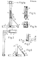
- the storage stand comprises two identical leg parts or members 1, 7 which are connected at their upper ends by a transverse beam 6.
- the transverse beam 6 is a so-called H profile beam in this case, but its cross section may as well be square or even circular.
- the cross-sectional shape of this beam is preferably a lying H or square.
- Figure 1 shows the construction of one of the leg members. It comprises a vertical support member or stilt 1, perpendicular to said transverse beam 6, of metal or equivalent material, preferably of steel, e.g. of stainless steel, or of aluminium.
- the support 1 is connected at its upper end perpendicularly to a round tube 3.
- the tube 3 is fitted inside a second round tube 4 of slightly larger diameter, preferably so that it may revolve freely inside this larger tube.
- the tube 4 is connected with a suitable method, for instance by welding, to the transverse beam 6.
- the support 1 is connected to the beam 7 via a pivotal shaft 8, 9. In practice, this is carried out by securing, e.g.
- a locking brace element 10 is pivotally attached to the beam 7 and the support 1.
- the brace is provided with pivots 11 and 12. The brace is locked to the beam 1 with a locking means, such as a lock pin 13, when the load is supported by the storage stands.
- the foot of the locking brace 10 is fitted to move in a gliding slot 14, fabricated into the side of the stand 1.
- a spring 15 which is attached at its one end to the support 1 and at its other end to the locking brace 10, preferably at the end which is fitted into the glide slot 14.
- another suitable damping element such as a shock absorber, may also be used.
- Figure 3 shows a situation in which the piece goods 18 are supported by the transverse beams 6 of the stands such that their leg members 4 form the contact faces against the base.
- driven A transportation bed 17 has been underneath the goods 18 in its longitudinal direction. whereby the bed 17 is also underneath the transverse beams 6.
- a pulling bar 19 is attached to the leg member of one of the storage stands.
- a force in the direction of arrow A is applied to the upper end of the stands via the pulling bar 19, moving the transportation bed forward in the direction of arrow A.
- the stands Pivoting around the pivotal shaft 8, 9, the stands are inclined by about 30...40°, and under the influence of the pulling force, the goods 18, leaning on the stands, are forced into a movement directed forwards and downwards, the radius of curvature of the path of movement being the distance between the pivotal shaft 8, 9 and the upper surface of the transverse beam 6.
- the leg members are detached from the transverse beam by detaching the tube 3 from the tube 4.
- the tube 3 and the leg member connected to it is rotable relative the transverse beam 6, whereby a maximum contact face is maintained between the goods ;H and the transverse beam 6 throughout the entire transfer movement and it is ensured that the goods remain steadily in support on the transverse beams 6 on the transportation bed.
- the upper and lower surfaces of the transverse beam 6 are in this case preferably parallel and plane.
- a stand shown in Figure 6 may also be used, having support 21 attached to a beam 22 via a pivotal shaft 23, 24 in the manner described above.
- the locking brace 25 is provided with a shock absorber or spring-loaded piston which is fitted into a cylinder. Also in this case the locking brace is attached at its both ends via pivots 26, 27 to the vertical suppport 21 and the beam 22, respectively.
- the brace 25 can be locked to its place by a locking pin 28.
- FIG. 7 A third possible embodiment is shown in Figure 7 in which a vertical support 31 and one leg of a beam 32 are welded together, forming an L-shaped support as a side view.
- the other leg of the beam 32 which is located in the inclination direction, is attached to the support via a pivot 33.
- Said leg is shaped such that it is at least slightly curving upwards, and to ensure the stable standing of the support, the underside of the leg is provided with a wedge bushing 36.
- the part of the leg facing the L-shaped support is skew.
- the wedge-shaped slot between the support and leg is provided with a locking wedge 34. The wedge must be removed before the support is brought into the inclination movement.
- the radius of curvature of the surface of the leg, which is rotated supported by the pivotal shaft, is preferably variable in order to prevent an accelerating inclination.
- the curved leg operates as a rocking chair, and the stand transfers the load by a tilt, remaining, however, in a standing position after the tilt.
- the transportation bed may be driven to underneath the load in its transverse direction by driving the bed only under the load, not under the load-supporting transverse beams.
- the load can be shifted onto the transportation bed so that it remains transversely on the bed.
- the storage stands are not left under the load and need not be dismantled for removal.
- the load may also remain on supports ready installed on the transportation bed, whereby, after the leg parts have been detached, the transverse beams can also be removed from the transportation bed.
Landscapes
- Engineering & Computer Science (AREA)
- Aviation & Aerospace Engineering (AREA)
- Mechanical Engineering (AREA)
- Conveying And Assembling Of Building Elements In Situ (AREA)
- Saccharide Compounds (AREA)
- Steroid Compounds (AREA)
- Control Of Vending Devices And Auxiliary Devices For Vending Devices (AREA)
- Discharge By Other Means (AREA)
- Die Bonding (AREA)
- Buffer Packaging (AREA)
- Processing Of Solid Wastes (AREA)
- Warehouses Or Storage Devices (AREA)
- On-Site Construction Work That Accompanies The Preparation And Application Of Concrete (AREA)
- Loading Or Unloading Of Vehicles (AREA)
- Auxiliary Methods And Devices For Loading And Unloading (AREA)
- Types And Forms Of Lifts (AREA)
- Intermediate Stations On Conveyors (AREA)
Priority Applications (1)
| Application Number | Priority Date | Filing Date | Title |
|---|---|---|---|
| AT85890294T ATE48115T1 (de) | 1984-12-05 | 1985-11-28 | Verfahren und vorrichtung zum transferieren von insbesondere bauelementen auf eine transportplattform. |
Applications Claiming Priority (2)
| Application Number | Priority Date | Filing Date | Title |
|---|---|---|---|
| FI844811 | 1984-12-05 | ||
| FI844811A FI72696C (fi) | 1984-12-05 | 1984-12-05 | Foerfarande och anordning foer oeverflyttning av foeretraedesvis byggnadselement pao ett transportunderlag. |
Publications (2)
| Publication Number | Publication Date |
|---|---|
| EP0184579A1 true EP0184579A1 (de) | 1986-06-11 |
| EP0184579B1 EP0184579B1 (de) | 1989-11-23 |
Family
ID=8520018
Family Applications (1)
| Application Number | Title | Priority Date | Filing Date |
|---|---|---|---|
| EP85890294A Expired EP0184579B1 (de) | 1984-12-05 | 1985-11-28 | Verfahren und Vorrichtung zum Transferieren von insbesondere Bauelementen auf eine Transportplattform |
Country Status (6)
| Country | Link |
|---|---|
| EP (1) | EP0184579B1 (de) |
| AT (1) | ATE48115T1 (de) |
| DE (1) | DE3574364D1 (de) |
| DK (1) | DK560785A (de) |
| FI (1) | FI72696C (de) |
| NO (1) | NO160915C (de) |
Cited By (2)
| Publication number | Priority date | Publication date | Assignee | Title |
|---|---|---|---|---|
| CN104175064A (zh) * | 2012-09-25 | 2014-12-03 | 安徽马钢工程技术集团有限公司 | 一种环件加工系统 |
| DE102016203778A1 (de) * | 2016-03-08 | 2017-09-14 | Fraunhofer-Gesellschaft zur Förderung der angewandten Forschung e.V. | Transporteinrichtung |
Families Citing this family (1)
| Publication number | Priority date | Publication date | Assignee | Title |
|---|---|---|---|---|
| CN102825435B (zh) * | 2012-09-25 | 2014-09-10 | 安徽马钢工程技术集团有限公司 | 一种环件加工系统及其方法及环件搬出装置 |
Citations (3)
| Publication number | Priority date | Publication date | Assignee | Title |
|---|---|---|---|---|
| DE1756629A1 (de) * | 1968-06-19 | 1970-04-02 | Gudrun Hoffstetter Geb Meyer | Verladevorrichtung |
| DE2122470A1 (de) * | 1970-05-18 | 1971-12-02 | Stefanelli, William L , Fresno, Calif (V St A ) | Frachtverladeeinrichtung |
| DE2022438A1 (de) * | 1970-05-08 | 1971-12-30 | Augsburg Nuernberg Ag Zweignie | Portal-Teleskopstuetzen fuer Wechselbruecken und Container |
-
1984
- 1984-12-05 FI FI844811A patent/FI72696C/fi not_active IP Right Cessation
-
1985
- 1985-11-28 EP EP85890294A patent/EP0184579B1/de not_active Expired
- 1985-11-28 DE DE8585890294T patent/DE3574364D1/de not_active Expired
- 1985-11-28 AT AT85890294T patent/ATE48115T1/de not_active IP Right Cessation
- 1985-12-04 DK DK560785A patent/DK560785A/da not_active Application Discontinuation
- 1985-12-04 NO NO854886A patent/NO160915C/no unknown
Patent Citations (3)
| Publication number | Priority date | Publication date | Assignee | Title |
|---|---|---|---|---|
| DE1756629A1 (de) * | 1968-06-19 | 1970-04-02 | Gudrun Hoffstetter Geb Meyer | Verladevorrichtung |
| DE2022438A1 (de) * | 1970-05-08 | 1971-12-30 | Augsburg Nuernberg Ag Zweignie | Portal-Teleskopstuetzen fuer Wechselbruecken und Container |
| DE2122470A1 (de) * | 1970-05-18 | 1971-12-02 | Stefanelli, William L , Fresno, Calif (V St A ) | Frachtverladeeinrichtung |
Cited By (4)
| Publication number | Priority date | Publication date | Assignee | Title |
|---|---|---|---|---|
| CN104175064A (zh) * | 2012-09-25 | 2014-12-03 | 安徽马钢工程技术集团有限公司 | 一种环件加工系统 |
| CN104175064B (zh) * | 2012-09-25 | 2016-08-24 | 安徽马钢工程技术集团有限公司 | 一种环件加工系统 |
| DE102016203778A1 (de) * | 2016-03-08 | 2017-09-14 | Fraunhofer-Gesellschaft zur Förderung der angewandten Forschung e.V. | Transporteinrichtung |
| DE102016203778B4 (de) * | 2016-03-08 | 2018-12-27 | Fraunhofer-Gesellschaft zur Förderung der angewandten Forschung e.V. | Transporteinrichtung |
Also Published As
| Publication number | Publication date |
|---|---|
| EP0184579B1 (de) | 1989-11-23 |
| FI844811L (fi) | 1986-06-06 |
| FI72696C (fi) | 1987-07-10 |
| DK560785A (da) | 1986-06-06 |
| FI72696B (fi) | 1987-03-31 |
| NO160915B (no) | 1989-03-06 |
| ATE48115T1 (de) | 1989-12-15 |
| DE3574364D1 (en) | 1989-12-28 |
| DK560785D0 (da) | 1985-12-04 |
| NO160915C (no) | 1989-06-14 |
| FI844811A0 (fi) | 1984-12-05 |
| NO854886L (no) | 1986-06-06 |
Similar Documents
| Publication | Publication Date | Title |
|---|---|---|
| EP0184293B1 (de) | Senkrecht stauende Stapel- und Abgabevorrichtung | |
| CN1131799C (zh) | 集装箱装卸装置或吊架 | |
| US4252358A (en) | Horizontal grapple | |
| US4402392A (en) | Portable belt conveyor, particularly a plate belt conveyor for crushing plants | |
| CN110939785B (zh) | 一种石油管道铺设安装施工方法 | |
| EP0457938A1 (de) | System zum Handhaben von gemischter Fracht | |
| CN1942377A (zh) | 在转移平台和运输交通工具之间转移装载物的设备和方法 | |
| EP0184579B1 (de) | Verfahren und Vorrichtung zum Transferieren von insbesondere Bauelementen auf eine Transportplattform | |
| EP0364487B1 (de) | Betriebsvorrichtung für eine lagerungsanordnung | |
| US3721354A (en) | Materials handling system | |
| US6626304B1 (en) | Portable trailer frame storage | |
| US20070029170A1 (en) | Rolling conveyor support | |
| WO1992012025A1 (en) | Vehicle, and method for loading/unloading such vehicle | |
| CN217075073U (zh) | 一种钢管辅助拆分分包装置 | |
| JPH08119420A (ja) | 管体の収納払出し装置 | |
| JP3011534U (ja) | 積載物運搬車輌の積載装置 | |
| RU2097312C1 (ru) | Грузоподъемное устройство преимущественно для монтажа мобильного объекта | |
| US7035713B2 (en) | Method for forming container racks | |
| US2808948A (en) | Self-loading vehicle for cylindrical tanks | |
| CA2525165C (en) | Load transfer system for flatbed trucks | |
| JPH06211303A (ja) | ガス充填方法及び設備 | |
| JP2003343087A (ja) | 建築現場用搬送装置及び建築現場の作業方法 | |
| CN213356297U (zh) | 一种卸车移送装置 | |
| CA1200534A (en) | System for handling compressible articles such as loaded bags | |
| JP2797088B2 (ja) | U形鋼矢板の積み重ね装置 |
Legal Events
| Date | Code | Title | Description |
|---|---|---|---|
| PUAI | Public reference made under article 153(3) epc to a published international application that has entered the european phase |
Free format text: ORIGINAL CODE: 0009012 |
|
| AK | Designated contracting states |
Kind code of ref document: A1 Designated state(s): AT BE CH DE FR GB IT LI NL SE |
|
| 17P | Request for examination filed |
Effective date: 19861126 |
|
| 17Q | First examination report despatched |
Effective date: 19870907 |
|
| RAP1 | Party data changed (applicant data changed or rights of an application transferred) |
Owner name: LOHJA PARMA ENGINEERING OY |
|
| GRAA | (expected) grant |
Free format text: ORIGINAL CODE: 0009210 |
|
| AK | Designated contracting states |
Kind code of ref document: B1 Designated state(s): AT BE CH DE FR GB IT LI NL SE |
|
| PG25 | Lapsed in a contracting state [announced via postgrant information from national office to epo] |
Ref country code: IT Free format text: LAPSE BECAUSE OF FAILURE TO SUBMIT A TRANSLATION OF THE DESCRIPTION OR TO PAY THE FEE WITHIN THE PRESCRIBED TIME-LIMIT;WARNING: LAPSES OF ITALIAN PATENTS WITH EFFECTIVE DATE BEFORE 2007 MAY HAVE OCCURRED AT ANY TIME BEFORE 2007. THE CORRECT EFFECTIVE DATE MAY BE DIFFERENT FROM THE ONE RECORDED. Effective date: 19891123 Ref country code: LI Effective date: 19891123 Ref country code: NL Effective date: 19891123 Ref country code: AT Effective date: 19891123 Ref country code: FR Free format text: THE PATENT HAS BEEN ANNULLED BY A DECISION OF A NATIONAL AUTHORITY Effective date: 19891123 Ref country code: CH Effective date: 19891123 Ref country code: BE Effective date: 19891123 Ref country code: SE Effective date: 19891123 |
|
| REF | Corresponds to: |
Ref document number: 48115 Country of ref document: AT Date of ref document: 19891215 Kind code of ref document: T |
|
| REF | Corresponds to: |
Ref document number: 3574364 Country of ref document: DE Date of ref document: 19891228 |
|
| PG25 | Lapsed in a contracting state [announced via postgrant information from national office to epo] |
Ref country code: GB Effective date: 19900123 |
|
| REG | Reference to a national code |
Ref country code: CH Ref legal event code: PL |
|
| EN | Fr: translation not filed | ||
| NLV1 | Nl: lapsed or annulled due to failure to fulfill the requirements of art. 29p and 29m of the patents act | ||
| PG25 | Lapsed in a contracting state [announced via postgrant information from national office to epo] |
Ref country code: DE Effective date: 19900801 |
|
| PLBE | No opposition filed within time limit |
Free format text: ORIGINAL CODE: 0009261 |
|
| STAA | Information on the status of an ep patent application or granted ep patent |
Free format text: STATUS: NO OPPOSITION FILED WITHIN TIME LIMIT |
|
| GBPC | Gb: european patent ceased through non-payment of renewal fee | ||
| 26N | No opposition filed |