EP0184599A1 - Messvorrichtung mit Verschiebungsfühler - Google Patents
Messvorrichtung mit Verschiebungsfühler Download PDFInfo
- Publication number
- EP0184599A1 EP0184599A1 EP84420204A EP84420204A EP0184599A1 EP 0184599 A1 EP0184599 A1 EP 0184599A1 EP 84420204 A EP84420204 A EP 84420204A EP 84420204 A EP84420204 A EP 84420204A EP 0184599 A1 EP0184599 A1 EP 0184599A1
- Authority
- EP
- European Patent Office
- Prior art keywords
- rule
- sensor
- displacement sensor
- graduation
- light sources
- Prior art date
- Legal status (The legal status is an assumption and is not a legal conclusion. Google has not performed a legal analysis and makes no representation as to the accuracy of the status listed.)
- Withdrawn
Links
- 238000006073 displacement reaction Methods 0.000 title claims abstract description 21
- 230000003287 optical effect Effects 0.000 claims abstract description 24
- 238000001514 detection method Methods 0.000 claims abstract description 5
- 230000001186 cumulative effect Effects 0.000 claims abstract description 4
- 230000010363 phase shift Effects 0.000 claims description 11
- 229910000831 Steel Inorganic materials 0.000 claims description 2
- 239000010959 steel Substances 0.000 claims description 2
- 238000005259 measurement Methods 0.000 abstract description 4
- 239000000463 material Substances 0.000 description 3
- 230000002093 peripheral effect Effects 0.000 description 3
- 239000000428 dust Substances 0.000 description 2
- 229920001971 elastomer Polymers 0.000 description 2
- 239000007788 liquid Substances 0.000 description 2
- 230000000630 rising effect Effects 0.000 description 2
- 239000000853 adhesive Substances 0.000 description 1
- 238000004026 adhesive bonding Methods 0.000 description 1
- 230000001070 adhesive effect Effects 0.000 description 1
- 239000002390 adhesive tape Substances 0.000 description 1
- 238000010586 diagram Methods 0.000 description 1
- 239000000806 elastomer Substances 0.000 description 1
- 229920001296 polysiloxane Polymers 0.000 description 1
- 230000001681 protective effect Effects 0.000 description 1
- 238000007789 sealing Methods 0.000 description 1
- 230000035945 sensitivity Effects 0.000 description 1
- 239000007787 solid Substances 0.000 description 1
- GYTROFMCUJZKNA-UHFFFAOYSA-N triethyl triethoxysilyl silicate Chemical compound CCO[Si](OCC)(OCC)O[Si](OCC)(OCC)OCC GYTROFMCUJZKNA-UHFFFAOYSA-N 0.000 description 1
Images

Classifications
-
- G—PHYSICS
- G01—MEASURING; TESTING
- G01D—MEASURING NOT SPECIALLY ADAPTED FOR A SPECIFIC VARIABLE; ARRANGEMENTS FOR MEASURING TWO OR MORE VARIABLES NOT COVERED IN A SINGLE OTHER SUBCLASS; TARIFF METERING APPARATUS; MEASURING OR TESTING NOT OTHERWISE PROVIDED FOR
- G01D5/00—Mechanical means for transferring the output of a sensing member; Means for converting the output of a sensing member to another variable where the form or nature of the sensing member does not constrain the means for converting; Transducers not specially adapted for a specific variable
- G01D5/26—Mechanical means for transferring the output of a sensing member; Means for converting the output of a sensing member to another variable where the form or nature of the sensing member does not constrain the means for converting; Transducers not specially adapted for a specific variable characterised by optical transfer means, i.e. using infrared, visible, or ultraviolet light
- G01D5/32—Mechanical means for transferring the output of a sensing member; Means for converting the output of a sensing member to another variable where the form or nature of the sensing member does not constrain the means for converting; Transducers not specially adapted for a specific variable characterised by optical transfer means, i.e. using infrared, visible, or ultraviolet light with attenuation or whole or partial obturation of beams of light
- G01D5/34—Mechanical means for transferring the output of a sensing member; Means for converting the output of a sensing member to another variable where the form or nature of the sensing member does not constrain the means for converting; Transducers not specially adapted for a specific variable characterised by optical transfer means, i.e. using infrared, visible, or ultraviolet light with attenuation or whole or partial obturation of beams of light the beams of light being detected by photocells
- G01D5/347—Mechanical means for transferring the output of a sensing member; Means for converting the output of a sensing member to another variable where the form or nature of the sensing member does not constrain the means for converting; Transducers not specially adapted for a specific variable characterised by optical transfer means, i.e. using infrared, visible, or ultraviolet light with attenuation or whole or partial obturation of beams of light the beams of light being detected by photocells using displacement encoding scales
-
- G—PHYSICS
- G01—MEASURING; TESTING
- G01D—MEASURING NOT SPECIALLY ADAPTED FOR A SPECIFIC VARIABLE; ARRANGEMENTS FOR MEASURING TWO OR MORE VARIABLES NOT COVERED IN A SINGLE OTHER SUBCLASS; TARIFF METERING APPARATUS; MEASURING OR TESTING NOT OTHERWISE PROVIDED FOR
- G01D5/00—Mechanical means for transferring the output of a sensing member; Means for converting the output of a sensing member to another variable where the form or nature of the sensing member does not constrain the means for converting; Transducers not specially adapted for a specific variable
- G01D5/26—Mechanical means for transferring the output of a sensing member; Means for converting the output of a sensing member to another variable where the form or nature of the sensing member does not constrain the means for converting; Transducers not specially adapted for a specific variable characterised by optical transfer means, i.e. using infrared, visible, or ultraviolet light
- G01D5/32—Mechanical means for transferring the output of a sensing member; Means for converting the output of a sensing member to another variable where the form or nature of the sensing member does not constrain the means for converting; Transducers not specially adapted for a specific variable characterised by optical transfer means, i.e. using infrared, visible, or ultraviolet light with attenuation or whole or partial obturation of beams of light
- G01D5/34—Mechanical means for transferring the output of a sensing member; Means for converting the output of a sensing member to another variable where the form or nature of the sensing member does not constrain the means for converting; Transducers not specially adapted for a specific variable characterised by optical transfer means, i.e. using infrared, visible, or ultraviolet light with attenuation or whole or partial obturation of beams of light the beams of light being detected by photocells
- G01D5/347—Mechanical means for transferring the output of a sensing member; Means for converting the output of a sensing member to another variable where the form or nature of the sensing member does not constrain the means for converting; Transducers not specially adapted for a specific variable characterised by optical transfer means, i.e. using infrared, visible, or ultraviolet light with attenuation or whole or partial obturation of beams of light the beams of light being detected by photocells using displacement encoding scales
- G01D5/34746—Linear encoders
- G01D5/34761—Protection devices, e.g. caps; Blowing devices
Definitions
- the present invention relates to a measuring device with displacement sensor intended more particularly for measuring distances.
- This device is of the type formed by a ruler provided with graduations of a determined pitch and a displacement sensor mounted displaceable above this ruler.
- the displacement sensor comprises at least one light source illuminating part of the graduation during the displacement of the sensor, photoelectric detection means capable of receiving the light reflected by the ruler surface and of emitting an output signal in the form of pulses. as well as cumulative counting means of the pulses emitted during the movement of the carriage.
- FR 2 506 928 In devices of this type such as, for example, that shown in FR 2 506 928, four light sources are used. These sources are not point sources and it is necessary to provide lenses to converge the light beam emitted by these lenses, in addition, as each incident beam covers several graduations, it is necessary to interpose masks on the path of the reflected beams in order to obtain an offset of these and to be able to have a reading.
- optical systems must be specially designed for the intended use, they involve special means of convergence and cannot use commercial optical systems, and they require the use of a carriage, on which the sensor is fixed. of movement, which is integral with the rule.
- optical systems are very complicated and therefore very expensive.
- the object of the present invention is to remedy these drawbacks and in particular to provide a measuring device with displacement sensor and counting of graduations, which is of simple and inexpensive design, while offering excellent precision, and which can be adapt on most machines and in particular on those comprising a movable element such as a carriage moving relative to another fixed guiding element such as a table.
- the device according to the invention comprises at least two light sources each emitting a thin light beam of width less than the pitch of the graduation of the rule and in that the light sources are out of phase with one another to the other. Therefore, as the phase shift of the light beams is carried out directly at the source, and not on the reflected beam as in known devices, and as each light beam scans only one graduation at a time, it is not necessary to provide masks on the path of the reflected beams, since each passage of the beam on a graduation causes the emission of a pulse and that there is thus a direct reading of each graduation.
- the incident light beams are out of phase with each other by an angle corresponding to a half-period of the output signal of the photoelectric means divided by the number of light sources.
- This arrangement makes it possible to have, for each graduation of the rule, a number of regularly spaced pulses equal at least to the number of light sources and therefore to increase the precision of the device accordingly.
- the output signal emitted by each photoelectric detection means has the form of a square signal, so that two pulses, -a rising edge and an output edge- are emitted for each light source at each passing a graduation and that the precision of the whole is still multiplied by two.
- each light source is formed by a direct reflection optical sensor incorporating a photo-detector.
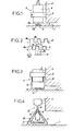
- the measuring device consists essentially of a rule (2) provided with graduations on its face (2a) and a displacement sensor (3).
- the graduated ruler (2) is formed for example by a flexible steel strip engraved at a determined pitch, n, for example, 0.4 mm.
- This rule (2) can be provided on its face (2b) opposite its graduated face (2a), with an adhesive allowing its fixing by simple gluing on the work table (1) of a machine tool (not shown on the drawing). It can also be fixed on this table by means of rivets.
- the displacement sensor (3) is fixed by means of a flange (5) on the mobile carriage (4) of the machine tool so as to move with it above the graduated rule (2), in parallel and at some distance above it.
- This displacement sensor comprises a cylindrical sleeve (6) at the bottom of which are fixed two optical sensors with direct reflection (7).
- Each optical sensor is of the type known under the trade name "HEDS 1000" and is formed by a light-emitting diode emitting a thin practically parallel light beam with a width equal to about 0.2 mm and by a photodetector directly receiving the reflected light beam. and capable of emitting an electrical pulse on each pass on a scale of the rule.
- Means for cumulative counting of electrical pulses emitted by each photodetector during the displacement of the sensor are also, in a manner known per se, mounted inside the cylindrical sleeve (6) thereof. These counting means are connected to a display device (not shown in the drawing) which permanently displays a number proportional to the number of pulses received and corresponding to the distance traveled by the sensor (3).
- the light beams emitted by the diodes (7) and, consequently, the light beams reflected by the rule (2) as well as the signals delivered by the photodetectors are phase shifted by an angle of 2 ⁇ 2p or ⁇ p since the period 21T of the signals delivered by the photodetectors corresponds to step n of the graduation.
- the phase shift of the light beams emitted by them is 90 °.
- the phase difference between them would be 2 ⁇ / 3, ie 60 °.
- This arrangement allows a very simple and inexpensive way to significantly increase the precision of the measurement device, in particular when the signals emitted by the photodetectors have the form of a square signal, as shown in FIG. 2.
- FIG. 2 In this FIG. 2 are shown the square signal (8) coming from the sinusoidal signal emitted by the photodetector of a first sensor (7), the square signal (9) coming from the sinusoidal signal emitted by the photodetector of the second sensor (7), this signal (9) being 90 ° out of phase with respect to the first signal (8), and the signal (10) transmitted to the counter.
- the signal (10) comprises, over the same period, four regularly distributed pulses, each pulse corresponding to a rising edge (8a, 9a) or to a falling edge (8b, 9b) of the square signals (8,9).
- the interval between two successive pulses of the signal (10) transmitted to the counter therefore corresponds to the step of the graduation divided by four, that is to say 0.1 mm for a step of 0.4 mm.
- the measurement thus obtained is very precise since it is carried out directly and without electronic analysis of the signal subject to drifts and therefore to inaccuracies as in the other known devices.
- the operation of the sensor (3) is completely independent of the ruler, since the latter performs a direct reading of the graduations, and it can therefore be used with any ruler comprising a graduation of any step insofar as this step is greater than the width of the light beams emitted.
- this measuring device can be easily adapted to most existing machine tools which generally include a mobile carriage. It suffices, in fact, to adapt a displacement sensor as described above on this carriage and to fix a simple ruler on the machine table using, for example, a double-sided adhesive tape, since the reading made by the sensor is completely independent of the type of rule used.
- This measuring device is not subject to any phenomenon of vibration or wear since there is no material contact between the rule and the sensor and is therefore very reliable; moreover, it minimizes the use of intermediate elements since there is a direct reading of each graduation.
- FIGS. 3 and 4 show other embodiments of the device making it possible to use it under more severe working conditions, in these figures the identical elements will be designated by the same references as in FIG. 1.
- the sensor (3) shown in FIG. 3 is provided at its lower part with a cylindrical pad (11), for example made of felt, which surrounds this sensor and is applied against the rule (2) so as to wipe it off. this during movement of the carriage (4).
- a cylindrical pad (11) for example made of felt, which surrounds this sensor and is applied against the rule (2) so as to wipe it off. this during movement of the carriage (4).
- the skate forms a closed chamber around the sensors, thus ensuring protection against abrasive solid splashes and stray light.
- the skate can also help keep the distance between the sensors and the ruler constant.
- Elastic means such as a spring (12) can also be provided between the flange (5) and the shoe (11) so as to press the latter against the rule (2).
- the measuring device shown in Figure 4 is designed for work in very difficult conditions with projection of liquids, dust and shavings.
- the displacement sensor (13) no longer has a cylindrical shape as before but has a narrowing (14). It is fixed by its upper part to the carriage (4) of a machine tool (not shown) and comprises at its lower part optical sensors (7), capable of moving during the movement of the carriage (4) in parallel and at a certain distance from a rule (2) fixed on the table (1) of the machine tool.
- the rule (2) is fixed to the bottom of a gutter or protective member (15) having a generally prismatic shape and comprising at its upper part two longitudinal lips (16,17) enclosing the narrowing (14) of the sensor (13).
- the material constituting the member (15) can be an elastomer, rubber or silicone having an elasticity and a coefficient of friction allowing a sufficient seal at the level of the narrowing (14) of the sensor (13) as well as the sliding of the latter.
- This gutter (15) protects the lower part of the sensor (13) against any projection of liquids, dust and shavings and therefore makes it possible to work in a difficult environment.
- This measuring device according to the invention can be used in any type of machine tool, press, shears, folder, etc.
- FIGS. 5 to 8 show a preferred embodiment of the sensor of FIG. 1, making it possible to easily and easily adjust the phase shift of the optical sensors or cells (7).
- the cells (7) are fixed in a cylindrical cell-carrying block (19) itself rotatably mounted inside the sleeve (6) at the lower end of the latter.
- a peripheral groove (20) is formed on the cell-holding block (19) and a segment (21) is housed in this groove (see Figures 5 and 6).
- Two diametrically opposed tapped holes (22) are provided in the cell holder (19) and extend in a longitudinal direction inside thereof, each hole (22) cutting the peripheral groove (20) as shown in Figure 6. Headless screws (23) are adapted to be screwed into each hole (22).
- each screw (23) When each screw (23) reaches the groove (20), it pushes the segment (21), which is housed therein, radially outward, as shown in phantom in Figure 6, and presses it against the inner wall of the sleeve (6) inside which is housed the cell holder block.
- the cell holder block (19) further comprises another peripheral groove (25) located still behind the groove (20) and capable of receiving an O-ring (not shown in the drawing) intended to ensure sealing and protecting the electronic circuit mounted inside the sleeve (6), behind the cell holder block (19), from the outside environment.
- the adjustment of the phase shift of the optical sensors (7) is obtained by rotating the cell holder block (19) relative to the cylindrical sleeve (6). Indeed, when the axis (26) of the two optical sensors (7) coincides with the longitudinal axis (27) of the rule (2), as is the case in FIG. 7, the distance between them ci, projected along the axis (27) of the rule (2), is equal to their real spacing (d).
- This adjustment will be made by rotating the block (19) and simultaneously controlling the phase shift of the square signals (8) and (9) using an oscilloscope.
- the cell holder block (19) is made integral with the cylindrical sleeve, as explained above using the grub screws (23).
- the flange (5) for fixing the displacement sensor (3) is provided with a centering pin (28), projecting radially inwards and capable of engaging in an associated longitudinal groove (29) formed along a director of the cylindrical sleeve (6).
- This arrangement makes it possible to remove the cylindrical sleeve (6) from the fixing flange (5) for example to clean it and to replace it as many times as necessary, without destroying the adjustment of the phase shift between the optical sensors (7 ), since the centering pin (28) cooperating with the associated longitudinal groove (29) always ensures the same positioning of the sleeve (6), that is to say of the sensor, relative to its fixing flange.
- centering pin could be replaced by any other equivalent means, for example a simple pin housed in a groove, and other means than the screws (23) and the segment (21) could be provided to make the block cell holder (19) integral with the sleeve.
- the table of the machine on which the rule is fixed is not necessarily fixed but can also be mobile.
- the invention is particularly suitable for measuring large distances.
- the device according to the invention can also replace proximity switches.
- the measuring device according to the invention can also be used for angular measurements on turrets, platforms, etc., using a ruler made of sufficiently flexible material to be installed on the periphery of these turrets, platforms.
- the gutter (15) is advantageously made in one piece, which was not possible previously for reasons of adjustment, while the independence of the sensor from the rule in the present device allows the realization of the gutter in one piece while obtaining the same precision.
Landscapes
- Physics & Mathematics (AREA)
- General Physics & Mathematics (AREA)
- Length Measuring Devices By Optical Means (AREA)
- Optical Transform (AREA)
Priority Applications (2)
| Application Number | Priority Date | Filing Date | Title |
|---|---|---|---|
| FR8314479A FR2551863B1 (fr) | 1983-09-12 | 1983-09-12 | Dispositif de mesure a capteur de deplacement independant |
| EP84420204A EP0184599A1 (de) | 1983-09-12 | 1984-12-07 | Messvorrichtung mit Verschiebungsfühler |
Applications Claiming Priority (2)
| Application Number | Priority Date | Filing Date | Title |
|---|---|---|---|
| FR8314479A FR2551863B1 (fr) | 1983-09-12 | 1983-09-12 | Dispositif de mesure a capteur de deplacement independant |
| EP84420204A EP0184599A1 (de) | 1983-09-12 | 1984-12-07 | Messvorrichtung mit Verschiebungsfühler |
Publications (1)
| Publication Number | Publication Date |
|---|---|
| EP0184599A1 true EP0184599A1 (de) | 1986-06-18 |
Family
ID=26095550
Family Applications (1)
| Application Number | Title | Priority Date | Filing Date |
|---|---|---|---|
| EP84420204A Withdrawn EP0184599A1 (de) | 1983-09-12 | 1984-12-07 | Messvorrichtung mit Verschiebungsfühler |
Country Status (2)
| Country | Link |
|---|---|
| EP (1) | EP0184599A1 (de) |
| FR (1) | FR2551863B1 (de) |
Families Citing this family (1)
| Publication number | Priority date | Publication date | Assignee | Title |
|---|---|---|---|---|
| FR2591736A1 (fr) * | 1985-12-17 | 1987-06-19 | Bazenet Jean Pierre | Systeme de mesure du deplacement lineaire d'une tige cylindrique telle qu'une tige de verin, verin adapte pour une telle mesure et son procede de fabrication |
Citations (7)
| Publication number | Priority date | Publication date | Assignee | Title |
|---|---|---|---|---|
| US3942895A (en) * | 1973-09-04 | 1976-03-09 | Teledyne, Inc. | Linear digital readout assembly for milling machines and the like and means for mounting same |
| FR2410251A1 (fr) * | 1977-11-25 | 1979-06-22 | Stanley Works | Metre a ruban a lecture numerique |
| GB2067283A (en) * | 1980-01-10 | 1981-07-22 | Gamon Eng Co Ltd V C | Determining relative movement |
| EP0040684A1 (de) * | 1980-05-02 | 1981-12-02 | Dr. Johannes Heidenhain GmbH | Präzisionslängenmesseinrichtung |
| FR2506928A1 (fr) * | 1981-05-27 | 1982-12-03 | Stanley Works | Dispositif optique sensible pour metres a ruban enroulable |
| EP0085787A2 (de) * | 1982-02-05 | 1983-08-17 | Dr. Johannes Heidenhain GmbH | Messeinrichtung |
| FR2534016A1 (fr) * | 1982-10-04 | 1984-04-06 | Bazenet Jean Pierre | Dispositif de mesure a capteur de deplacement |
-
1983
- 1983-09-12 FR FR8314479A patent/FR2551863B1/fr not_active Expired
-
1984
- 1984-12-07 EP EP84420204A patent/EP0184599A1/de not_active Withdrawn
Patent Citations (7)
| Publication number | Priority date | Publication date | Assignee | Title |
|---|---|---|---|---|
| US3942895A (en) * | 1973-09-04 | 1976-03-09 | Teledyne, Inc. | Linear digital readout assembly for milling machines and the like and means for mounting same |
| FR2410251A1 (fr) * | 1977-11-25 | 1979-06-22 | Stanley Works | Metre a ruban a lecture numerique |
| GB2067283A (en) * | 1980-01-10 | 1981-07-22 | Gamon Eng Co Ltd V C | Determining relative movement |
| EP0040684A1 (de) * | 1980-05-02 | 1981-12-02 | Dr. Johannes Heidenhain GmbH | Präzisionslängenmesseinrichtung |
| FR2506928A1 (fr) * | 1981-05-27 | 1982-12-03 | Stanley Works | Dispositif optique sensible pour metres a ruban enroulable |
| EP0085787A2 (de) * | 1982-02-05 | 1983-08-17 | Dr. Johannes Heidenhain GmbH | Messeinrichtung |
| FR2534016A1 (fr) * | 1982-10-04 | 1984-04-06 | Bazenet Jean Pierre | Dispositif de mesure a capteur de deplacement |
Also Published As
| Publication number | Publication date |
|---|---|
| FR2551863B1 (fr) | 1986-10-31 |
| FR2551863A1 (fr) | 1985-03-15 |
Similar Documents
| Publication | Publication Date | Title |
|---|---|---|
| EP0342123B1 (de) | Verfahren zur Positionierung eines Objektes in bezug auf eine Ebene, Längenmessverfahren und Vorrichtung zur Durchführung des Verfahrens | |
| EP0159210B1 (de) | Optische Vorrichtung zum Messen der Annäherung an einer Fläche und Verfahren zum Wiedergewinnen des Profils einer solchen Fläche | |
| FR2601443A1 (fr) | Capteur de position et son application a la telemetrie, notamment pour la robotique spatiale | |
| FR2491615A1 (fr) | Procede de mesure optoelectronique et dispositifs pour la determination de la qualite de surfaces a reflexion diffuse | |
| EP3019822B1 (de) | Optische vorrichtung zur messung eines physikalischen parameters und zugehöriges verfahren | |
| FR2559577A1 (fr) | Procede de mesure par trace polygonal et dispositif de mesure | |
| EP0015820A1 (de) | Vorrichtung zum berührungslosen und markierungslosen Messen von linearen Geschwindigkeiten | |
| EP0712009A1 (de) | Integriertes Winkelabweichungs-Messsystem | |
| EP0647829B1 (de) | Verfahren und Vorrichtung zur geometrischen Kontrolle eines Fahrzeugs | |
| EP0964226B1 (de) | Ablesevorrichtung für hochauflösenden optischen Kodierer | |
| FR2506007A1 (fr) | Dispositif pour la mesure des coordonnees d'une sphere tournante et procede de fabrication d'une partie dudit dispositif | |
| EP1111347B1 (de) | Positionsgeber | |
| EP0184599A1 (de) | Messvorrichtung mit Verschiebungsfühler | |
| CH684212A5 (fr) | Dispositif optique à interférométrie en lumière blanche. | |
| FR2656688A1 (fr) | Dispositif de mesure du niveau d'un liquide dans un reservoir par determination optique de la position d'un flotteur. | |
| EP0190181B1 (de) | Verfahren und vorrichtung zur stellungsbestimmung eines beweglichen organs mittels elementen mit variablen, optischen eigenschaften | |
| EP0023902B1 (de) | Optische vorrichtung zur regelung oder steuerung von licht | |
| EP0048688B1 (de) | Verfahren zur optischen Detektion und/oder zum Messen einer Deformation und/oder einer Versetzung eines Objektes oder eines Objektteiles, Vorrichtung für die Ausführung dieses Verfahrens und Anwendung des Verfahrens | |
| EP0065429A1 (de) | Verfahren und Vorrichtung zur optischen Wegmessung und Verwendung zur schrittweisen Photoreproduktion | |
| CH375909A (fr) | Dispositif de détermination de la position d'un organe mobile de machine | |
| FR2596514A1 (fr) | Capteur de deplacement | |
| WO2014102382A1 (fr) | Dispositif de repérage d'un échantillon, et système d'observation comportant un tel dispositif de repérage | |
| FR2591736A1 (fr) | Systeme de mesure du deplacement lineaire d'une tige cylindrique telle qu'une tige de verin, verin adapte pour une telle mesure et son procede de fabrication | |
| CH646784A5 (en) | Device for measuring linear dimensions or variations in these dimensions using an optical reader, and with electronic interpolation | |
| EP0070446A2 (de) | Optische Inkrementaldetektionsvorrichtung der relativen Verschiebung zweier materieller Objekte |
Legal Events
| Date | Code | Title | Description |
|---|---|---|---|
| PUAI | Public reference made under article 153(3) epc to a published international application that has entered the european phase |
Free format text: ORIGINAL CODE: 0009012 |
|
| AK | Designated contracting states |
Kind code of ref document: A1 Designated state(s): AT BE CH DE FR GB IT LI LU NL SE |
|
| STAA | Information on the status of an ep patent application or granted ep patent |
Free format text: STATUS: THE APPLICATION IS DEEMED TO BE WITHDRAWN |
|
| 18D | Application deemed to be withdrawn |
Effective date: 19870219 |