EP0184628A2 - Tête de lecture pour codeur de déplacements, en particulier codeur d'angles - Google Patents
Tête de lecture pour codeur de déplacements, en particulier codeur d'angles Download PDFInfo
- Publication number
- EP0184628A2 EP0184628A2 EP19850112649 EP85112649A EP0184628A2 EP 0184628 A2 EP0184628 A2 EP 0184628A2 EP 19850112649 EP19850112649 EP 19850112649 EP 85112649 A EP85112649 A EP 85112649A EP 0184628 A2 EP0184628 A2 EP 0184628A2
- Authority
- EP
- European Patent Office
- Prior art keywords
- hybrid
- light source
- light
- grating
- circuit
- Prior art date
- Legal status (The legal status is an assumption and is not a legal conclusion. Google has not performed a legal analysis and makes no representation as to the accuracy of the status listed.)
- Granted
Links
Images


Classifications
-
- G—PHYSICS
- G01—MEASURING; TESTING
- G01D—MEASURING NOT SPECIALLY ADAPTED FOR A SPECIFIC VARIABLE; ARRANGEMENTS FOR MEASURING TWO OR MORE VARIABLES NOT COVERED IN A SINGLE OTHER SUBCLASS; TARIFF METERING APPARATUS; MEASURING OR TESTING NOT OTHERWISE PROVIDED FOR
- G01D5/00—Mechanical means for transferring the output of a sensing member; Means for converting the output of a sensing member to another variable where the form or nature of the sensing member does not constrain the means for converting; Transducers not specially adapted for a specific variable
- G01D5/26—Mechanical means for transferring the output of a sensing member; Means for converting the output of a sensing member to another variable where the form or nature of the sensing member does not constrain the means for converting; Transducers not specially adapted for a specific variable characterised by optical transfer means, i.e. using infrared, visible, or ultraviolet light
- G01D5/32—Mechanical means for transferring the output of a sensing member; Means for converting the output of a sensing member to another variable where the form or nature of the sensing member does not constrain the means for converting; Transducers not specially adapted for a specific variable characterised by optical transfer means, i.e. using infrared, visible, or ultraviolet light with attenuation or whole or partial obturation of beams of light
- G01D5/34—Mechanical means for transferring the output of a sensing member; Means for converting the output of a sensing member to another variable where the form or nature of the sensing member does not constrain the means for converting; Transducers not specially adapted for a specific variable characterised by optical transfer means, i.e. using infrared, visible, or ultraviolet light with attenuation or whole or partial obturation of beams of light the beams of light being detected by photocells
- G01D5/347—Mechanical means for transferring the output of a sensing member; Means for converting the output of a sensing member to another variable where the form or nature of the sensing member does not constrain the means for converting; Transducers not specially adapted for a specific variable characterised by optical transfer means, i.e. using infrared, visible, or ultraviolet light with attenuation or whole or partial obturation of beams of light the beams of light being detected by photocells using displacement encoding scales
- G01D5/34707—Scales; Discs, e.g. fixation, fabrication, compensation
- G01D5/34715—Scale reading or illumination devices
Definitions
- Such a scanning head is known from DE-AS 1 153 909.
- a substantial part of the parallel light beam is transmitted or covered the light beam.
- a movement of the grating against each other caused by a moire modulation sequences of Li G htimpulsen, which are detected by the detector means, and can be counted by a acted upon by the output signal of the detector means counter. It is possible to provide a very fine division of the grating without the intensity of the light pulse becoming too low, as would be the case when scanning a single gap in the grating.
- Talbot stripes images of this grating
- the spacing of the Talbot stripes corresponds to the lattice constant w of the lattice.
- the distances of the planes from the grating are whole multiples of w 2 / X if ⁇ is the wavelength of the light used. From DE-PS 22 38 413 it is known to provide two grating pairs which come into effect one after the other in the beam path and are arranged at this distance w 2 / a from one another to improve the degree of modulation. A similar arrangement is described in the dissertation "Three-Grid Step Generator” by Jörg Wilhelm, TU Hannover, 1978 pages 33 to 41.
- the known scanning heads for high-resolution angular step encoders are too large for some applications. They are unsuitable for applications under extreme environmental conditions such as strongly fluctuating temperatures, thermal shock loads, vibrations and high accelerations.
- the known scanning heads are difficult to assemble and adjust with the required precision.
- the upper limit frequency for the transmission of the output signals of the detector means must be very high.
- the maximum permissible angular velocity of an angular step encoder is obtained by dividing the upper limit frequency of the amplifier by the number of grid bars or angular increments per revolution.
- the amplifiers are arranged at a spatial distance from the detector means. The capacitances and inductances of the relatively long lines reduce the upper limit frequency. There is also the danger interference by electromagnetic fields on these lines.
- the invention has for its object to make a pacemaker of the type mentioned small and compact, to make it insensitive to extreme environmental conditions, to assemble and adjust with little effort and to achieve a high cut-off frequency for high speeds with high angular resolution.
- a hybrid circuit is known to be a microcircuit in which discrete components and semiconductor components are applied to a network of passive components and lines, which is vapor-deposited on ceramic or glass (Graf "Modern Dictionary of Electronics” Howard W Sams and Co. Inc., The Bobbs-Merrill Co., Inc. 4 ed. Page 272).
- Such hybrid circuits are included in "hybrid packages”.
- the light source and the detector are applied to such a hybrid circuit and hermetically sealed in a hybrid housing. This makes the scanning head largely insensitive to environmental influences.
- a light-emitting diode serves as the light source. It is small and insensitive to vibrations and accelerations. However, their light output is lower than that of a commonly used incandescent lamp.
- a very short focal length collimator optics must be used, which captures as large a part of the light emitted by the light emitting diode as possible.
- the detector sits on a hybrid circuit, which also forms the amplifier for the detector signal.
- Embodiments of the invention are the subject of the dependent claims.
- An angular step encoder contains a disk 10 which is rotatable about an axis 12, a transmitter part 14 and a receiver part 16.
- the disk 10 has an annular, finely divided grid 18 with radial grid bars.
- the grid 18 has, for example, 8,000 grid webs or increments per revolution.
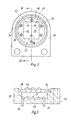
- the transmitter part 14 contains a hybrid circuit 20 on which five light-emitting diodes 22 are applied.
- the light-emitting diodes 22 with the hybrid circuit 20 are seated in a flat, hermetically sealed hybrid housing 24.
- the hybrid housing 24 has a lower housing part 26 and a cover 28.
- the lower housing part 26 forms a depression 30, which is adjoined by an annular shoulder or support surface 32.
- the cover 28 sits sealingly on the shoulder 32.
- the hybrid circuit 20 sits on the base of the recess 30. 34 denotes isolated connection pins.
- the cover 28 contains, aligned with the light-emitting diodes 22, five short-focal lenses 36 which serve as collimator optics.
- the light emitting diodes 22 are located in the focal points of the lenses, so that each light emitting diode 22 and lens 36 generate a parallel light beam.
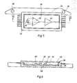
- the receiver part 16 contains a hybrid circuit 38.
- the hybrid circuit 38 carries detectors 40 in the form of photodiodes, as indicated in FIG. 5.
- the hybrid circuit 38 also contains, as is also indicated in FIG. 5, an amplifier 42 and a switching stage 44 for each of the detectors 40.
- the hybrid circuit 38 with the detectors 40 is seated in a flat, rectangular hybrid housing 46.
- the hybrid housing 46 has a lower housing part 48 and a lid 50.
- the lower housing part 48 forms a recess 52 to which a shoulder is attached or contact surface 54 connects.
- the cover 50 lies sealingly on the bearing surface 54.
- a strip 56 with fastening holes 58 sits on the hybrid housing.
- the hybrid housing 24 of the transmitter part 14 is connected to the strip 56 by screws 60 with the interposition of a spacer 62.
- the two hybrid housings 24 and 46 are thus kept at a fixed distance from one another.
- the disk 10 projects between these two hybrid housings 24 and 46.
- the cover 50 of the hybrid housing 46 is designed as a fixed grid 64 with radial grid webs.
- the parallel light beams thus fall through the movable grating 18 of the pane 10 and the fixed grating 64 formed by the cover 50 onto the detectors 40.
- a detector 40 is aligned with one of the light-emitting diodes 22.
- a monolithic light-emitting diode chip array can also be provided.
- the detectors can also be formed by other photo receivers such as photo elements or photoresistors.
- the lenses can be Fresnel lenses.
- FIG. 7 and 8 show another embodiment of the transmitter part, which is characterized by a different arrangement of the light-emitting diodes and lenses.
Landscapes
- Physics & Mathematics (AREA)
- General Physics & Mathematics (AREA)
- Optical Transform (AREA)
- Length Measuring Devices By Optical Means (AREA)
Applications Claiming Priority (2)
| Application Number | Priority Date | Filing Date | Title |
|---|---|---|---|
| DE19843444878 DE3444878A1 (de) | 1984-12-08 | 1984-12-08 | Abtastkopf fuer schrittgeber, insbesondere winkelschrittgeber |
| DE3444878 | 1984-12-08 |
Publications (3)
| Publication Number | Publication Date |
|---|---|
| EP0184628A2 true EP0184628A2 (fr) | 1986-06-18 |
| EP0184628A3 EP0184628A3 (en) | 1988-02-10 |
| EP0184628B1 EP0184628B1 (fr) | 1991-01-30 |
Family
ID=6252287
Family Applications (1)
| Application Number | Title | Priority Date | Filing Date |
|---|---|---|---|
| EP85112649A Expired - Lifetime EP0184628B1 (fr) | 1984-12-08 | 1985-10-05 | Tête de lecture pour codeur de déplacements, en particulier codeur d'angles |
Country Status (3)
| Country | Link |
|---|---|
| US (1) | US4700065A (fr) |
| EP (1) | EP0184628B1 (fr) |
| DE (2) | DE3444878A1 (fr) |
Cited By (5)
| Publication number | Priority date | Publication date | Assignee | Title |
|---|---|---|---|---|
| FR2596514A1 (fr) * | 1986-04-01 | 1987-10-02 | Bazenet Jean Pierre | Capteur de deplacement |
| EP0838665A1 (fr) * | 1996-10-28 | 1998-04-29 | Mitutoyo Corporation | Dispositif de détection optique de déplacement |
| WO2003054486A1 (fr) * | 2001-12-20 | 2003-07-03 | Agilent Technologies, Inc. | Dispositif a codeur optique |
| SG116401A1 (en) * | 1998-08-20 | 2005-11-28 | Koyo Seiko Co | Optical rotary encoder. |
| US7518157B2 (en) | 2003-11-08 | 2009-04-14 | Dr. Johannes Heidenhain Gmbh | Optoelectronic component assembly |
Families Citing this family (8)
| Publication number | Priority date | Publication date | Assignee | Title |
|---|---|---|---|---|
| US4806034A (en) * | 1988-02-10 | 1989-02-21 | Polaroid Corporation | Write head controller with grid synchronization |
| DE3820906A1 (de) * | 1988-06-21 | 1989-12-28 | Bodenseewerk Geraetetech | Winkelabgriff hoher aufloesung |
| DE3905508A1 (de) * | 1989-02-23 | 1990-08-30 | Messerschmitt Boelkow Blohm | Mikromechanisches bauelement |
| DE3939132A1 (de) * | 1989-11-27 | 1991-05-29 | Bodenseewerk Geraetetech | Stellungssensor fuer landeklappenhebel bei flugzeugen |
| DE4230405B4 (de) * | 1991-09-12 | 2005-11-17 | Mitsubishi Denki K.K. | Positions-Detektor |
| EP0867693A1 (fr) * | 1997-03-27 | 1998-09-30 | Koyo Seiko Co., Ltd. | Codeur optique rotatif |
| DE19855828A1 (de) | 1998-12-03 | 2000-06-08 | Heidenhain Gmbh Dr Johannes | Dreidimensionales Meßmodul |
| DE19957822A1 (de) * | 1999-11-19 | 2001-05-23 | Heidenhain Gmbh Dr Johannes | Abtasteinrichtung für Positionsmeßsysteme zur Abtastung einer Meßteilung |
Family Cites Families (7)
| Publication number | Priority date | Publication date | Assignee | Title |
|---|---|---|---|---|
| US4263506A (en) * | 1978-12-21 | 1981-04-21 | Hewlett-Packard Company | Pulse generating apparatus |
| US4338517A (en) * | 1979-01-15 | 1982-07-06 | Perrine Warren L | Shaft rotation sensor |
| IT1129862B (it) * | 1980-11-17 | 1986-06-11 | Olivetti & Co Spa | Trasduttore ottico |
| US4508965A (en) * | 1982-03-05 | 1985-04-02 | Hewlett-Packard Company | Uniaxially collimated light source for optical shaft angle encoders |
| WO1984001057A1 (fr) * | 1982-09-09 | 1984-03-15 | Plessey Overseas | Dispositif optique |
| DE3327849A1 (de) * | 1983-08-02 | 1985-02-14 | Dr. Johannes Heidenhain Gmbh, 8225 Traunreut | Lichtelektrische laengen- oder winkelmesseinrichtung |
| DE3331118C2 (de) * | 1983-08-30 | 1986-05-07 | Flachglas AG, 8510 Fürth | Bohrspindel für eine Glasbohrmaschine, mit am werkstückseitigen Ende angeordnetem Bohrer sowie Senker |
-
1984
- 1984-12-08 DE DE19843444878 patent/DE3444878A1/de not_active Withdrawn
-
1985
- 1985-10-05 DE DE8585112649T patent/DE3581609D1/de not_active Expired - Fee Related
- 1985-10-05 EP EP85112649A patent/EP0184628B1/fr not_active Expired - Lifetime
- 1985-11-25 US US06/801,199 patent/US4700065A/en not_active Expired - Lifetime
Cited By (8)
| Publication number | Priority date | Publication date | Assignee | Title |
|---|---|---|---|---|
| FR2596514A1 (fr) * | 1986-04-01 | 1987-10-02 | Bazenet Jean Pierre | Capteur de deplacement |
| EP0838665A1 (fr) * | 1996-10-28 | 1998-04-29 | Mitutoyo Corporation | Dispositif de détection optique de déplacement |
| US5841133A (en) * | 1996-10-28 | 1998-11-24 | Mitutoyo Corporation | Optical displacement detecting apparatus having gratings and a light receiving chip |
| SG116401A1 (en) * | 1998-08-20 | 2005-11-28 | Koyo Seiko Co | Optical rotary encoder. |
| WO2003054486A1 (fr) * | 2001-12-20 | 2003-07-03 | Agilent Technologies, Inc. | Dispositif a codeur optique |
| GB2395004A (en) * | 2001-12-20 | 2004-05-12 | Agilent Technologies Inc | Optical encoder device |
| GB2395004B (en) * | 2001-12-20 | 2006-01-18 | Agilent Technologies Inc | Optical encoder device |
| US7518157B2 (en) | 2003-11-08 | 2009-04-14 | Dr. Johannes Heidenhain Gmbh | Optoelectronic component assembly |
Also Published As
| Publication number | Publication date |
|---|---|
| US4700065A (en) | 1987-10-13 |
| DE3581609D1 (de) | 1991-03-07 |
| EP0184628B1 (fr) | 1991-01-30 |
| DE3444878A1 (de) | 1986-06-12 |
| EP0184628A3 (en) | 1988-02-10 |
Similar Documents
| Publication | Publication Date | Title |
|---|---|---|
| DE69322569T2 (de) | Vorrichtung zur Erfassung von Rotationsinformationen | |
| EP0638784B1 (fr) | Dispositif de mesure photo-électrique de longueurs et d'angles | |
| DE69227009T2 (de) | Opto-elektronischer Skalenleseapparat | |
| DE69320716T3 (de) | Gerät zur Detektion von Verschiebungsinformation | |
| EP1923673B1 (fr) | Dispositif de mesure de position | |
| EP0425726B1 (fr) | Dispositif de mesure de position | |
| DE69418819T3 (de) | Drehkodierer | |
| EP0137099B1 (fr) | Appareil de mesure | |
| EP0184628A2 (fr) | Tête de lecture pour codeur de déplacements, en particulier codeur d'angles | |
| EP0262349A2 (fr) | Dispositif photoélectrique pour la mesure d'angles | |
| DE3816247A1 (de) | System zur entfernungsmessung | |
| EP0083689B1 (fr) | Dispositif photo-électrique incrémentiel pour mesurer des longueurs ou des angles | |
| DE10058239B4 (de) | Positionsmeßeinrichtung | |
| EP0363620A1 (fr) | Dispositif photoélectrique pour mesurer la position | |
| DE3816248A1 (de) | System zur entfernungsmessung | |
| EP2735848B1 (fr) | Dispositif optique de mesure de la position | |
| EP0626564B1 (fr) | Dispositif de mesure d'angles ou de longueur | |
| DE3113166C2 (de) | Vorrichtung zum elektro-optischen Ablesen eines Schriftstückes oder dergl. | |
| DE10116599A1 (de) | Optische Positionsmesseinrichtung | |
| DE4303162A1 (de) | Photoelektrisches Längen- bzw. Winkelmeßsystem | |
| DE19524725C1 (de) | Fotoelektrischer Kodierer zum Abtasten optischer Strukturen | |
| DE19518714A1 (de) | Geber mit diffraktiven optischen Abbildungselementen | |
| DE3632084A1 (de) | Optischer encoder | |
| EP0590162B1 (fr) | Capteur linéaire ou angulaire | |
| DE4323624C2 (de) | Lichtelektrische Längen- oder Winkelmeßeinrichtung |
Legal Events
| Date | Code | Title | Description |
|---|---|---|---|
| PUAI | Public reference made under article 153(3) epc to a published international application that has entered the european phase |
Free format text: ORIGINAL CODE: 0009012 |
|
| AK | Designated contracting states |
Kind code of ref document: A2 Designated state(s): DE FR GB |
|
| PUAL | Search report despatched |
Free format text: ORIGINAL CODE: 0009013 |
|
| AK | Designated contracting states |
Kind code of ref document: A3 Designated state(s): DE FR GB |
|
| 17P | Request for examination filed |
Effective date: 19880809 |
|
| 17Q | First examination report despatched |
Effective date: 19891009 |
|
| GRAA | (expected) grant |
Free format text: ORIGINAL CODE: 0009210 |
|
| RIN1 | Information on inventor provided before grant (corrected) |
Inventor name: KORDULLA, HANS Inventor name: SCHMID, GUENTER Inventor name: JANSEN, DIRK, DR. |
|
| AK | Designated contracting states |
Kind code of ref document: B1 Designated state(s): DE FR GB |
|
| REF | Corresponds to: |
Ref document number: 3581609 Country of ref document: DE Date of ref document: 19910307 |
|
| GBT | Gb: translation of ep patent filed (gb section 77(6)(a)/1977) | ||
| ET | Fr: translation filed | ||
| PLBE | No opposition filed within time limit |
Free format text: ORIGINAL CODE: 0009261 |
|
| STAA | Information on the status of an ep patent application or granted ep patent |
Free format text: STATUS: NO OPPOSITION FILED WITHIN TIME LIMIT |
|
| 26N | No opposition filed | ||
| PGFP | Annual fee paid to national office [announced via postgrant information from national office to epo] |
Ref country code: FR Payment date: 20010827 Year of fee payment: 17 |
|
| PGFP | Annual fee paid to national office [announced via postgrant information from national office to epo] |
Ref country code: GB Payment date: 20010924 Year of fee payment: 17 |
|
| PGFP | Annual fee paid to national office [announced via postgrant information from national office to epo] |
Ref country code: DE Payment date: 20011219 Year of fee payment: 17 |
|
| REG | Reference to a national code |
Ref country code: GB Ref legal event code: IF02 |
|
| PG25 | Lapsed in a contracting state [announced via postgrant information from national office to epo] |
Ref country code: GB Free format text: LAPSE BECAUSE OF NON-PAYMENT OF DUE FEES Effective date: 20021005 |
|
| PG25 | Lapsed in a contracting state [announced via postgrant information from national office to epo] |
Ref country code: DE Free format text: LAPSE BECAUSE OF NON-PAYMENT OF DUE FEES Effective date: 20030501 |
|
| GBPC | Gb: european patent ceased through non-payment of renewal fee |
Effective date: 20021005 |
|
| PG25 | Lapsed in a contracting state [announced via postgrant information from national office to epo] |
Ref country code: FR Free format text: LAPSE BECAUSE OF NON-PAYMENT OF DUE FEES Effective date: 20030630 |
|
| REG | Reference to a national code |
Ref country code: FR Ref legal event code: ST |