EP0184818B1 - Dispositif de positionnement pour plaquette de coupe - Google Patents
Dispositif de positionnement pour plaquette de coupe Download PDFInfo
- Publication number
- EP0184818B1 EP0184818B1 EP85115684A EP85115684A EP0184818B1 EP 0184818 B1 EP0184818 B1 EP 0184818B1 EP 85115684 A EP85115684 A EP 85115684A EP 85115684 A EP85115684 A EP 85115684A EP 0184818 B1 EP0184818 B1 EP 0184818B1
- Authority
- EP
- European Patent Office
- Prior art keywords
- circular
- cutting
- recess
- segment
- head
- Prior art date
- Legal status (The legal status is an assumption and is not a legal conclusion. Google has not performed a legal analysis and makes no representation as to the accuracy of the status listed.)
- Expired
Links
- 238000005520 cutting process Methods 0.000 claims abstract description 45
- 230000002093 peripheral effect Effects 0.000 description 4
- 238000004519 manufacturing process Methods 0.000 description 3
- 238000010276 construction Methods 0.000 description 2
- 238000003801 milling Methods 0.000 description 2
- 210000002435 tendon Anatomy 0.000 description 2
- 238000003754 machining Methods 0.000 description 1
- 239000002245 particle Substances 0.000 description 1
Images




Classifications
-
- B—PERFORMING OPERATIONS; TRANSPORTING
- B23—MACHINE TOOLS; METAL-WORKING NOT OTHERWISE PROVIDED FOR
- B23B—TURNING; BORING
- B23B27/00—Tools for turning or boring machines; Tools of a similar kind in general; Accessories therefor
- B23B27/14—Cutting tools of which the bits or tips or cutting inserts are of special material
- B23B27/16—Cutting tools of which the bits or tips or cutting inserts are of special material with exchangeable cutting bits or cutting inserts, e.g. able to be clamped
- B23B27/1659—Cutting tools of which the bits or tips or cutting inserts are of special material with exchangeable cutting bits or cutting inserts, e.g. able to be clamped with plate-like exchangeable cutting inserts
-
- B—PERFORMING OPERATIONS; TRANSPORTING
- B23—MACHINE TOOLS; METAL-WORKING NOT OTHERWISE PROVIDED FOR
- B23B—TURNING; BORING
- B23B2205/00—Fixation of cutting inserts in holders
- B23B2205/12—Seats for cutting inserts
Definitions
- the invention relates to a cutting holder for cutting inserts, in particular indexable inserts, which consists of a shaft and a recess made in the head thereof for receiving the cutting insert, the recess having a base area and two side faces arranged at an angle to one another for positioning the cutting insert, one of the two side faces is rotatably arranged with respect to the other and is formed by a circular section piece which is arranged in a circular cutout of the head.
- Cutting holders with rotatably arranged side faces are known from DE-B-2 210 816 and GB-A-2086 273, but they are complex to manufacture and to operate and require relatively narrow tolerances in the production of cutting holders and cutting inserts.
- Cutters like inserts, are mass-produced, i.e. that is, efforts are made to adhere to predetermined tolerances, and the manufacturing process requires the greatest possible tolerances, since these are easier to adhere to, and in many cases the application demands very narrow tolerances.
- the present invention is therefore based on the object of providing a cutting holder which can be manufactured with coarser tolerances, but which nevertheless enables the cutting insert to rest properly on the side surfaces of the recess in the head of the cutting holder.
- a cutting holder for cutting inserts in particular indexable inserts, which consists of a shank and a recess in the head for receiving the cutting insert, the recess having a base area and two side surfaces arranged at an angle to one another for positioning the cutting insert, one of the both side surfaces rotatably arranged relative to the other and is formed by a circular section piece which is arranged in a circular section-shaped recess of the head, with the characteristic feature that the cylinder jacket of the circular section piece has an open area which is arranged opposite its tendon.
- the invention provides that the cylinder jacket of the circular section piece has a free surface which is arranged opposite its tendon, which is in engagement with the insert inserted.
- this free area in the rear area of the circular section piece reduces its contact surface and thus reduces the friction, so that the circular section piece adapts more easily to the position of the cutting plate. It is also essential that this compensates for tolerances that occur when machining the outer surface of the circular segment piece and the circular segment-shaped recess.
- this rotatable side surface is provided with two lugs and only these two lugs are in engagement with the contact side of the cutting plate.
- This configuration also makes it possible to center cutting inserts that are crowned or have the shape of a polygon, that is to say more than four side surfaces. In this case, the two lugs engage on different side surfaces, so that, in conjunction with the one rigid side surface, the cutting insert is properly positioned.
- the rotatable side surface is formed by a circular segment piece, which is arranged in a circular segment-shaped recess of the head.
- the circular section piece has a greater height than the height of the circular section shaped recess, with the radius being essentially the same as that of the circular section.
- This milling cutter must be inserted into a side surface above the base of the recess, a disc spring with a rear open area being inserted into this cutout, which can be both open and covered at the top, ie towards the surface of the head of the cutting holder.
- an advantageous embodiment of the invention provides that the circular section piece is provided with a shoulder.
- This approach is located in the upper third of the height of the side surfaces, so it only engages in the upper third of the insert, so that there is a space in the lower area, whereby the lower edge of the insert is exposed in any case and not by a possibly unclean system, as can occur due to fine dirt particles, affects the positioning of the insert.
- the rigid side surface is also expediently provided with a projection, so that clean positioning is also possible here and the cutting plates are prevented from being beaked.
- a preferred embodiment of the invention provides that the circular segment-shaped recess below the base surface is designed as a blind hole.
- This constructive measure makes it possible to introduce the receptacle for the rotatable side surface by simply making a hole in the head of the cutting holder, the rotatable side surface in this case being designed as a cylinder which has a region extending above the base surface of the recess has milled surface, which in turn can be provided with a shoulder.
- the cylinder is covered by a base plate in the area of the base of the recess, this base plate serving as a support for the cutting plate.
- the cylinder is captively arranged in the cutter holder, ie not only is there a very simple possibility of producing the movable side surface, the piece to be used is also secured against falling out and thus against loss.
- An expedient embodiment of the invention provides that the circular segment-shaped recess has an undercut.
- the analog section section which thus represents a disc with a leg running on the circumference of the disc, engages in this undercut. This construction also ensures that the circular section piece is securely mounted and guided in the cutting holder.
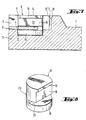
- the shank (1) of the cutting tool carries at its front end the head (13) which has the recess (2).
- the recess (2) is limited on one side by the rigid side surface (7).
- the footplate (4) rests on the base (6) of the recess (2) and is fastened to it by the footplate screw (5).
- the cutting plate (3) is arranged, which rests with a peripheral surface on the extension (10 ') of the rigid side surface (7) and with a further peripheral surface in contact with the extension (10) of the circular section piece (8) stands.
- the cutting plate (3) When inserting the cutting plate (3) into the recess (2), the cutting plate (3) is pressed against the rigid side surface (7) and slides along it until the circular section piece (8) lies against the second peripheral surface of the cutting plate (3) Has.
- the circular segment piece (8) rotates in the circular segment-shaped recess (9) until the chord (14) comes into full contact with the peripheral surface of the cutting plate (3).
- the circular segment-shaped recess (9) has an undercut (11) into which the leg (17) of the circular segment piece (8) engages.
- Two lugs (15) on the circular section piece (8) ensure two point-shaped systems even in the event that the cutting plate (3) is spherical in this edge area.
- Figure 6 shows the circular section piece (8) shown in perspective, which is delimited by the cylinder jacket (24), which is located above the leg (17).
- the height (h1) of the circular segment piece, which is perpendicular to the chord (14), is greater than the height (h2) of the circular segment-shaped recess (9).
- the circular segment piece (8) always protrudes from the circular segment-shaped recess (9).
- the circular section piece (8) is designed as a cylinder which has a milled surface (16) which is provided with a shoulder (10).
- the circular area (19) of this cylinder is located in the blind hole (12) and is partially covered by the base plate (4).
- a groove (22) is arranged under the milled surface (16), so that a limited rotation of the cylinder is possible even when the base plate (4) is screwed on.
- the inserted circular section piece (8) is shown as a disc spring in the circular segment-shaped recess (9).
- This disc spring protrudes beyond the lateral boundary of the circular segment-shaped recess (9) to allow rotation, and is by the pin (20) which the bore (21) in the disc spring, i.e.. H. the circular section (8), reaches through, secured against falling out.
- the diameter of the bore (21) is a multiple of the diameter of the pin (20) to allow the disc spring to move.
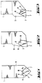
- FIGS. 11, 12a and 12b A circular section piece (8) is shown in FIGS. 11, 12a and 12b, which is provided with a rear open area (22).
- the cylinder jacket (23) is divided by the free surface (22) so that only two remaining cylinder surfaces (24) remain.
- the contact of the circumferential surface (23) with the recess (9) in the form of a circular segment is thereby considerably reduced, but at the same time, by dimensioning the width of the free surface (22), it is ensured that even with the greatest possible rotational movement of the circular segment piece (8) in the shaft (1)
- Another contact of the two remaining cylinder surfaces (24) against the circular cutout (9) is achieved.
Landscapes
- Engineering & Computer Science (AREA)
- Mechanical Engineering (AREA)
- Harvester Elements (AREA)
- Nonmetal Cutting Devices (AREA)
- Details Of Cutting Devices (AREA)
- Cutting Tools, Boring Holders, And Turrets (AREA)
- Drilling Tools (AREA)
- Polyoxymethylene Polymers And Polymers With Carbon-To-Carbon Bonds (AREA)
Claims (5)
Priority Applications (1)
| Application Number | Priority Date | Filing Date | Title |
|---|---|---|---|
| AT85115684T ATE41889T1 (de) | 1984-12-13 | 1985-12-10 | Schneidhalter fuer schneidplatten. |
Applications Claiming Priority (2)
| Application Number | Priority Date | Filing Date | Title |
|---|---|---|---|
| DE19843445423 DE3445423A1 (de) | 1984-12-13 | 1984-12-13 | Schneidhalter fuer schneidplatten |
| DE3445423 | 1984-12-13 |
Publications (2)
| Publication Number | Publication Date |
|---|---|
| EP0184818A1 EP0184818A1 (fr) | 1986-06-18 |
| EP0184818B1 true EP0184818B1 (fr) | 1989-04-05 |
Family
ID=6252639
Family Applications (1)
| Application Number | Title | Priority Date | Filing Date |
|---|---|---|---|
| EP85115684A Expired EP0184818B1 (fr) | 1984-12-13 | 1985-12-10 | Dispositif de positionnement pour plaquette de coupe |
Country Status (3)
| Country | Link |
|---|---|
| EP (1) | EP0184818B1 (fr) |
| AT (1) | ATE41889T1 (fr) |
| DE (2) | DE3445423A1 (fr) |
Families Citing this family (3)
| Publication number | Priority date | Publication date | Assignee | Title |
|---|---|---|---|---|
| SE509595C2 (sv) * | 1996-01-25 | 1999-02-15 | Sandvik Ab | Skär för spånavskiljande metallbearbetning |
| IL131463A (en) | 1999-08-18 | 2003-05-29 | Iscar Ltd | Cutting insert pocket |
| SE0100250L (sv) | 2001-01-30 | 2002-07-31 | Sandvik Ab | Verktygshållare |
Family Cites Families (8)
| Publication number | Priority date | Publication date | Assignee | Title |
|---|---|---|---|---|
| DD48135A (fr) * | ||||
| DE1402937B2 (de) * | 1960-03-04 | 1971-10-14 | Feldmühle AG, 4000 Düsseldorf | Schneidwerkzeug mit auswechselbar angeordnetem schneidkoerper |
| FR2094446A5 (fr) * | 1970-06-22 | 1972-02-04 | Unital | |
| BE794309A (fr) * | 1972-03-07 | 1973-05-16 | Hertel Karl | Outil a ecrouter les arbres par enlevement des copeaux |
| FR2234075A1 (en) * | 1973-06-20 | 1975-01-17 | Fruit Rene | Positioning method for cutting inserts - uses positioning points passing through the shank of the support |
| CH604990A5 (fr) * | 1975-03-04 | 1978-09-29 | Zapp Werkzeug & Maschf R | |
| FR2465543A1 (fr) * | 1979-09-21 | 1981-03-27 | Electro Metallurg Ste Indle | Dispositif de reglage micrometrique d'une plaquette de coupe fixee par vis sur un support |
| IL61368A (en) * | 1980-10-29 | 1984-05-31 | Iscar Ltd | Holder assembly for tools such as apertured cutting inserts |
-
1984
- 1984-12-13 DE DE19843445423 patent/DE3445423A1/de not_active Withdrawn
-
1985
- 1985-12-10 EP EP85115684A patent/EP0184818B1/fr not_active Expired
- 1985-12-10 DE DE8585115684T patent/DE3569215D1/de not_active Expired
- 1985-12-10 AT AT85115684T patent/ATE41889T1/de not_active IP Right Cessation
Also Published As
| Publication number | Publication date |
|---|---|
| EP0184818A1 (fr) | 1986-06-18 |
| DE3445423A1 (de) | 1986-06-19 |
| ATE41889T1 (de) | 1989-04-15 |
| DE3569215D1 (en) | 1989-05-11 |
Similar Documents
| Publication | Publication Date | Title |
|---|---|---|
| DE69416365T2 (de) | Schneidwerkzeug | |
| DE69909070T2 (de) | Modulare schneidwerkzeuganordnung | |
| DE69715462T2 (de) | Schneideinsatz für spanabnehmende bearbeitung von metallen | |
| AT396762B (de) | Innendrehmeissel | |
| EP1486279A1 (fr) | Plaquette de coupe pour tourner et fraiser | |
| EP0131784B1 (fr) | Outil de décroutage | |
| DE69718740T2 (de) | Werkzeugmaschinenschneidewerkzeugpositioniervorrichtung | |
| EP1462199A1 (fr) | Plaquette de coupe et outil de fraisage | |
| DE102015122697B4 (de) | Schneidwerkzeugbaugruppe | |
| DE68902495T2 (de) | Fraeswerkzeug. | |
| DE1552296A1 (de) | Schneidwerkzeug | |
| DE29609541U1 (de) | Stanzvorrichtung | |
| WO1994007665A1 (fr) | Tete porte-lames | |
| EP0769341B1 (fr) | Outil pour l'usinage de pièces par enlèvement de copeaux | |
| DE3031216A1 (de) | Spannfutter fuer gewindebohrer. | |
| DE2065306A1 (de) | Bohrkopf | |
| EP1033210B1 (fr) | Plaquette de coupe, en particulier pour un outil de fraisage | |
| WO2003022495A1 (fr) | Matrice de decoupage pour outils servant a l'usinage de pieces par enlevement de copeaux | |
| EP0184818B1 (fr) | Dispositif de positionnement pour plaquette de coupe | |
| DE4330174A1 (de) | Drehbares Schneidwerkzeug | |
| EP1136162A1 (fr) | Fraise à surfacer et à fraise des coins | |
| DE10305854A1 (de) | Viereckiger Schneideinsatz für Fräser mit negativem Radialwinkel der Schneiden für das dreidimensionale Fräsen aus dem Vollen | |
| DE102006005572B4 (de) | Stanzvorrichtung | |
| AT397219B (de) | Rotierendes spanabhebendes werkzeug | |
| DE2505515A1 (de) | Schneidwerkzeug |
Legal Events
| Date | Code | Title | Description |
|---|---|---|---|
| PUAI | Public reference made under article 153(3) epc to a published international application that has entered the european phase |
Free format text: ORIGINAL CODE: 0009012 |
|
| 17P | Request for examination filed |
Effective date: 19851210 |
|
| AK | Designated contracting states |
Kind code of ref document: A1 Designated state(s): AT BE CH DE FR GB IT LI LU NL SE |
|
| 17Q | First examination report despatched |
Effective date: 19880426 |
|
| ITF | It: translation for a ep patent filed | ||
| GRAA | (expected) grant |
Free format text: ORIGINAL CODE: 0009210 |
|
| AK | Designated contracting states |
Kind code of ref document: B1 Designated state(s): AT BE CH DE FR GB IT LI LU NL SE |
|
| REF | Corresponds to: |
Ref document number: 41889 Country of ref document: AT Date of ref document: 19890415 Kind code of ref document: T |
|
| REF | Corresponds to: |
Ref document number: 3569215 Country of ref document: DE Date of ref document: 19890511 |
|
| ET | Fr: translation filed | ||
| GBT | Gb: translation of ep patent filed (gb section 77(6)(a)/1977) | ||
| PG25 | Lapsed in a contracting state [announced via postgrant information from national office to epo] |
Ref country code: LU Free format text: LAPSE BECAUSE OF NON-PAYMENT OF DUE FEES Effective date: 19891231 |
|
| PLBE | No opposition filed within time limit |
Free format text: ORIGINAL CODE: 0009261 |
|
| STAA | Information on the status of an ep patent application or granted ep patent |
Free format text: STATUS: NO OPPOSITION FILED WITHIN TIME LIMIT |
|
| 26N | No opposition filed | ||
| PGFP | Annual fee paid to national office [announced via postgrant information from national office to epo] |
Ref country code: LU Payment date: 19901031 Year of fee payment: 6 |
|
| PGFP | Annual fee paid to national office [announced via postgrant information from national office to epo] |
Ref country code: DE Payment date: 19901105 Year of fee payment: 6 |
|
| PGFP | Annual fee paid to national office [announced via postgrant information from national office to epo] |
Ref country code: GB Payment date: 19901114 Year of fee payment: 6 |
|
| PGFP | Annual fee paid to national office [announced via postgrant information from national office to epo] |
Ref country code: FR Payment date: 19901120 Year of fee payment: 6 |
|
| PGFP | Annual fee paid to national office [announced via postgrant information from national office to epo] |
Ref country code: BE Payment date: 19901121 Year of fee payment: 6 |
|
| PGFP | Annual fee paid to national office [announced via postgrant information from national office to epo] |
Ref country code: CH Payment date: 19901123 Year of fee payment: 6 |
|
| PGFP | Annual fee paid to national office [announced via postgrant information from national office to epo] |
Ref country code: SE Payment date: 19901228 Year of fee payment: 6 Ref country code: AT Payment date: 19901228 Year of fee payment: 6 |
|
| ITTA | It: last paid annual fee | ||
| PGFP | Annual fee paid to national office [announced via postgrant information from national office to epo] |
Ref country code: NL Payment date: 19901231 Year of fee payment: 6 |
|
| EPTA | Lu: last paid annual fee | ||
| PG25 | Lapsed in a contracting state [announced via postgrant information from national office to epo] |
Ref country code: GB Effective date: 19911210 Ref country code: AT Effective date: 19911210 |
|
| PG25 | Lapsed in a contracting state [announced via postgrant information from national office to epo] |
Ref country code: SE Effective date: 19911211 |
|
| PG25 | Lapsed in a contracting state [announced via postgrant information from national office to epo] |
Ref country code: LI Effective date: 19911231 Ref country code: CH Effective date: 19911231 Ref country code: BE Effective date: 19911231 |
|
| BERE | Be: lapsed |
Owner name: FELDMUHLE A.G. Effective date: 19911231 |
|
| PG25 | Lapsed in a contracting state [announced via postgrant information from national office to epo] |
Ref country code: NL Effective date: 19920701 |
|
| GBPC | Gb: european patent ceased through non-payment of renewal fee | ||
| NLV4 | Nl: lapsed or anulled due to non-payment of the annual fee | ||
| PG25 | Lapsed in a contracting state [announced via postgrant information from national office to epo] |
Ref country code: FR Effective date: 19920831 |
|
| REG | Reference to a national code |
Ref country code: CH Ref legal event code: PL |
|
| PG25 | Lapsed in a contracting state [announced via postgrant information from national office to epo] |
Ref country code: DE Effective date: 19920901 |
|
| REG | Reference to a national code |
Ref country code: FR Ref legal event code: ST |
|
| EUG | Se: european patent has lapsed |
Ref document number: 85115684.4 Effective date: 19920704 |