EP0184821B1 - Dispositif de positionnement précis - Google Patents
Dispositif de positionnement précis Download PDFInfo
- Publication number
- EP0184821B1 EP0184821B1 EP85115716A EP85115716A EP0184821B1 EP 0184821 B1 EP0184821 B1 EP 0184821B1 EP 85115716 A EP85115716 A EP 85115716A EP 85115716 A EP85115716 A EP 85115716A EP 0184821 B1 EP0184821 B1 EP 0184821B1
- Authority
- EP
- European Patent Office
- Prior art keywords
- mounting means
- member mounting
- flexure
- base
- axis
- Prior art date
- Legal status (The legal status is an assumption and is not a legal conclusion. Google has not performed a legal analysis and makes no representation as to the accuracy of the status listed.)
- Expired - Lifetime
Links
- 238000005520 cutting process Methods 0.000 claims description 14
- 238000000034 method Methods 0.000 claims description 8
- 230000007246 mechanism Effects 0.000 claims description 3
- 238000010276 construction Methods 0.000 description 2
- 238000011109 contamination Methods 0.000 description 2
- 230000009471 action Effects 0.000 description 1
- 239000003638 chemical reducing agent Substances 0.000 description 1
- 238000006073 displacement reaction Methods 0.000 description 1
- 239000000428 dust Substances 0.000 description 1
- 238000005461 lubrication Methods 0.000 description 1
- 238000003754 machining Methods 0.000 description 1
- 238000012423 maintenance Methods 0.000 description 1
- 238000004519 manufacturing process Methods 0.000 description 1
- 238000012986 modification Methods 0.000 description 1
- 230000004048 modification Effects 0.000 description 1
- NJPPVKZQTLUDBO-UHFFFAOYSA-N novaluron Chemical compound C1=C(Cl)C(OC(F)(F)C(OC(F)(F)F)F)=CC=C1NC(=O)NC(=O)C1=C(F)C=CC=C1F NJPPVKZQTLUDBO-UHFFFAOYSA-N 0.000 description 1
- 238000010079 rubber tapping Methods 0.000 description 1
- 239000000725 suspension Substances 0.000 description 1
- 230000037303 wrinkles Effects 0.000 description 1
Images


Classifications
-
- B—PERFORMING OPERATIONS; TRANSPORTING
- B23—MACHINE TOOLS; METAL-WORKING NOT OTHERWISE PROVIDED FOR
- B23Q—DETAILS, COMPONENTS, OR ACCESSORIES FOR MACHINE TOOLS, e.g. ARRANGEMENTS FOR COPYING OR CONTROLLING; MACHINE TOOLS IN GENERAL CHARACTERISED BY THE CONSTRUCTION OF PARTICULAR DETAILS OR COMPONENTS; COMBINATIONS OR ASSOCIATIONS OF METAL-WORKING MACHINES, NOT DIRECTED TO A PARTICULAR RESULT
- B23Q1/00—Members which are comprised in the general build-up of a form of machine, particularly relatively large fixed members
- B23Q1/25—Movable or adjustable work or tool supports
- B23Q1/26—Movable or adjustable work or tool supports characterised by constructional features relating to the co-operation of relatively movable members; Means for preventing relative movement of such members
- B23Q1/34—Relative movement obtained by use of deformable elements, e.g. piezoelectric, magnetostrictive, elastic or thermally-dilatable elements
- B23Q1/36—Springs
-
- Y—GENERAL TAGGING OF NEW TECHNOLOGICAL DEVELOPMENTS; GENERAL TAGGING OF CROSS-SECTIONAL TECHNOLOGIES SPANNING OVER SEVERAL SECTIONS OF THE IPC; TECHNICAL SUBJECTS COVERED BY FORMER USPC CROSS-REFERENCE ART COLLECTIONS [XRACs] AND DIGESTS
- Y10—TECHNICAL SUBJECTS COVERED BY FORMER USPC
- Y10T—TECHNICAL SUBJECTS COVERED BY FORMER US CLASSIFICATION
- Y10T403/00—Joints and connections
- Y10T403/54—Flexible member is joint component
-
- Y—GENERAL TAGGING OF NEW TECHNOLOGICAL DEVELOPMENTS; GENERAL TAGGING OF CROSS-SECTIONAL TECHNOLOGIES SPANNING OVER SEVERAL SECTIONS OF THE IPC; TECHNICAL SUBJECTS COVERED BY FORMER USPC CROSS-REFERENCE ART COLLECTIONS [XRACs] AND DIGESTS
- Y10—TECHNICAL SUBJECTS COVERED BY FORMER USPC
- Y10T—TECHNICAL SUBJECTS COVERED BY FORMER US CLASSIFICATION
- Y10T82/00—Turning
- Y10T82/10—Process of turning
-
- Y—GENERAL TAGGING OF NEW TECHNOLOGICAL DEVELOPMENTS; GENERAL TAGGING OF CROSS-SECTIONAL TECHNOLOGIES SPANNING OVER SEVERAL SECTIONS OF THE IPC; TECHNICAL SUBJECTS COVERED BY FORMER USPC CROSS-REFERENCE ART COLLECTIONS [XRACs] AND DIGESTS
- Y10—TECHNICAL SUBJECTS COVERED BY FORMER USPC
- Y10T—TECHNICAL SUBJECTS COVERED BY FORMER US CLASSIFICATION
- Y10T82/00—Turning
- Y10T82/13—Pattern section
- Y10T82/135—Cam-controlled cutter
-
- Y—GENERAL TAGGING OF NEW TECHNOLOGICAL DEVELOPMENTS; GENERAL TAGGING OF CROSS-SECTIONAL TECHNOLOGIES SPANNING OVER SEVERAL SECTIONS OF THE IPC; TECHNICAL SUBJECTS COVERED BY FORMER USPC CROSS-REFERENCE ART COLLECTIONS [XRACs] AND DIGESTS
- Y10—TECHNICAL SUBJECTS COVERED BY FORMER USPC
- Y10T—TECHNICAL SUBJECTS COVERED BY FORMER US CLASSIFICATION
- Y10T82/00—Turning
- Y10T82/25—Lathe
- Y10T82/2531—Carriage feed
- Y10T82/2541—Slide rest
Definitions
- the present invention relates to positioning devices and more particularly to a positioning device which is used to provide controlled, accurate positioning of a movable member, as well as to a method for controlling accurate positioning of said movable member.
- Positioning devices currently utilized in positioning a member such as a tool or cutter typically include a slide, sometimes moving with a ball bearing arrangement, and a leadscrew which provides the driving force and positioning. These slides are subject to three problems which prohibit discrete movements of less than 0,00127mm (50 millionths of an inch). These three problems are "stick-slip", “backlash” and wear of bearing surfaces.
- “Stick-slip” is the tendancy of the moving member of a slide to stick or freeze when stationary, due to friction between the adjacent surfaces. Although this problem is initially overcome by a ball bearing slide, wear and contamination eventually produce "stick-slip". The only recourse to this problem is to infeed an additional amount until the slide moves or to tap the slide with a hammer until it moves. When using the first method, the resulting movement is usually a lunge or jump which can be two or three times the desired movement. The tapping of the slide with a hammer, although crude, can be effective but cannot be consistently relied upon for extremely accurate positioning.
- “Backlash” is the tendency of leadscrews to develop a free movement before exerting any pressure on the slide member. This is particularly true where a reverse movement is desired, such as when the member is advanced too far and a small retraction is needed. Theoretically, “backlash” occurs since clearance is required between a screw and a nut to prevent it from locking up. However, when the screw is reversed, it uses the back side of the thread and develops a “play” or “backlash” when traversing from the front side of the thread to the back side of the thread through the clearance provided. This "backlash” may seem insignificant but does prevent precise, minute incremental positioning which is frequently needed.
- the third major problem with current positioning devices is the wear of the surfaces of the slide. As stated above, initial results are satisfactory, especially with a ball bearing slide. However, friction between the surfaces produces wear which eventually leads to play in the slide and an inevitable inaccurate positioning. This problem is enhanced by contamination from foreign matter which is produced by most machining operations.
- US-A-1,122,713 discloses a tool adjustment for lathes. This patent discloses a slide which moves a cutting tool and has weights attached to the slide to provide an axial load on the slide which is driven by a screw feed.
- US-A-1,322,352 discloses an automatic lathe using a slide which moves a cutting tool and is driven by a screw feed.
- US-A-2,065,966 discloses an elastic holder for cutting tools.
- This patent discloses a tool holder in which the tool can give way elastically, if the tool or workpiece are in danger of being damaged or broken.
- the elastic member is constituted by a plate spring or by a plurality of superimposed plate springs.
- US-A-2,370,742 discloses another tool holder which is capable of yielding to avoid distortion or breakage and also uses plate springs.
- US-A-2,377,239 discloses a set-up and adjustment means whereby a cutting tool is moved on a slide which is driven by a cam capable of being adjusted by a screw.
- the slide is additionally subjected to an axial force provided by helical springs.
- US-A-2,391,142 discloses a tool holder which will yield to permit the tool to move from the workpiece.
- This yielding means is provided by a helical spring having a spring rate which may be varied to provide different tensions to control the action of the tool.
- US-A-2,852,966 provides a cutting tool holder which will retract from the cutting surface without marring and is capable of minute adjustments.
- This patent discloses a tool holder which moves along a slide subjected to a force provided by a helical spring.
- US-A-3,361,018 discloses a tool holder for lathes in the form of a pair of flat parallel leaf springs having their lower edges secured to the lathe and their upper ends mounting a tool holder.
- GB-A-535 962 finally, from which the present invention starts out in its pre-characterizing part, is directed to improvements in tailstocks for precision grinders or laths.
- This document shows a tailstock member which is carried by a pair of laminated flat springs such that it is movable in a single direction, i.e. in a direction along its longitudinal axis.
- the flat springs are fixedly mounted at their respective ends and carry the tailstock member midways. Due to the fixed ends of the flat springs on the one hand only small movements of the tailstock member are possible and on the other hand high forces are necessary to move the tailstock member, this leading to undesirable wear in any driving means and hence to increasing inaccuracy over a longer period of time.
- a method for controlling accurate positioning of a movable member according to this invention is claimed in claim 12.
- the apparatus of the present invention provides a positioning device which is capable of repeated accurate positioning of a member within five millionths of an inch. This accuracy has never been achieved before and is provided in an inexpensive, dependable and more rugged apparatus which is not susceptible to the problems described above and which will continue to function in the most hostile manufacturing environments with a minimal amount of maintenance.
- the apparatus of the present invention differs from the previously proposed apparatus by providing an incremental positioning device which is not subjected to friction between surfaces, does not exhibit any free movement before positioning is started or reversed, and moves in an absolute straight line.
- an apparatus for controlling accurate positioning of a movable member comprising a base, mounting means spaced from the base, at least two mounting blocks mounted on the base, and flexure means fixed transversely of and to the mounting means and fixed at each end thereof to one of the mounting blocks.
- the mounting means is able to move forwardly and rearwardly along an axis thereof spaced from the base and is subjected to an axial force by the flexure means.
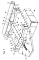
- Fig. 1 is a front perspective view of a grinder attached to an accurate positioning apparatus which is constructed according to the teachings of the present invention and which is shown in conjunction with a lathe;
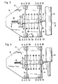
- Fig. 2 is a top perspective view of one preferred embodiment of the accurate positioning apparatus of the present invention shown with a cutting tool mounted at one end of a mounting member of the apparatus;
- Fig. 3 is a top plan view of the apparatus shown in Fig. 2 and is shown in its at-rest position;
- Fig. 4 is a top plan view of the apparatus in its working position;
- Fig. 5 is a vertical sectional view of the apparatus shown in Fig. 3 and is taken along line 5-5 of Fig. 3; and
- Fig. 6 is a sectional view of a mounting block of the apparatus shown in Fig. 3 and is taken along line 6-6 of Fig. 3.
- FIG. 1 a very accurate positioning apparatus 10 constructed according to the present invention which is shown with a grinder 12 mounted thereon for grinding a workpiece 14 mounted on a lathe 16.
- the apparatus 10 is mounted on a pedestal 18 adjacent to, or part of, the lathe 16 and is driven by a screw feed drive 20 including a motor or gear reducer 22.
- the apparatus 10 includes a base 24 on which are mounted four blocks 31-34.
- Each block 31-34 has a throughbore 41, 42, 43 or 44 (Fig. 2) for receiving a pin or dowel 51, 52, 53 or 54 (Fig. 2), each of which is fixed at its lower end to the base 24.
- the apparatus 10 further includes a mounting bar 60 positioned for movement over the base 24 and having a proximal end 62 upon which the screw feed drive 20 acts, a distal end 64, and a top side 66 on which the grinder 12 is mounted.
- the mounting bar 60 is supported for movement over the base 24 by a flexing mechanism 70 which includes two elongate flat plate springs 72 and 74 which are curved, in order to be fixed at each end, respectively, to blocks 31, 32 and 33, 34.
- the mounting bar 60 is mounted on the flat springs 72 and 74 as will be described in greater detail below.
- the positioning apparatus 10 is shown in Fig. 2 with a cutting tool 76 mounted on the distal end 64 of the mounting bar 60 for cutting a workpiece 78.
- the distal end 64 can have a special construction for accommodating or mounting a tool such as the cutting tool 76. Also, bolt holes 81-84 can be provided in the top side 66 of the bar 60 for mounting a machine tool such as the grinder 12 shown in Fig 1.
- the mounting bar 60 has two parallel spaced slots 86 and 88.
- the flat spring 72 is received in the slot 86 and the flat spring 74 is received in the slot 88.
- the flat springs 72 and 74 are fixed in proper position in and relative to the bar 60 by dowel pins 90 and 92, respectively and clamped to the bar 60 by fasteners (not shown) received through end blocks 94 and 96 as best shown in Figs. 3 and 4.
- the screw feed drive 20 acts on the end block 94 to move the mounting bar 60. This movement permits the cutting tool 76 or the grinder 12 to engage or disengage the workpiece 14 or 78 to be machined. Since the mounting bar 60 is mounted suspended above the base 24, no lubrication between these two members is needed and the mounting bar 60 is not restricted by any dirt, dust, residue, etc. which may accumulate from the workpiece 14 or 78 to be machined. This method of mounting the bar 60 prevents any "stick-slip" described earlier.
- Each of the blocks 31-34 has a slot 101, 102,103 or 104 therein as best shown in Fig. 6 which is a sectional view though block 31 and shows slot 101.
- An end 106 of flat spring 72 is received in the slot 101 and held in place by a dowel pin 108 which can be a threaed set screw 108 as shown.
- the flat flexure springs 72 and 74 it is desirable to mount the flat flexure springs 72 and 74 in such a way as to provide an axial force on the mounting bar 60 acting on same in a direction toward the proximal end 62 of the mounting bar 60.
- This axial force is established by selecting springs 72 and 74 with a desired spring range and by providing the flat springs 72, 74 with an arch pointing toward the proximal end 62 of the mounting bar 60 when the flexure springs 72 and 74 are mounted in mounting blocks 31-34. This axial force prevents backlash in the screw feed drive 20 as described earlier.
- the flat flexure springs 72 and 74 can be flat leaf springs such as used in vehicle suspension systems.
- the pivotal mounting of the mounting blocks 31-34 and the distance D (Fig. 6) between pivot axis 110 of pin 51 and the plane 112 of flat spring 22 (actually the center plane of slot 101) are chosen so that (a) the mounting blocks 31-34 are free to pivot about the pins 51-54 and allow the screw feed drive to move the mounting bar 60 freely against the axial force provided by the flat flexure springs 72 and 74 and (b) when the slots 86 and 88 are aligned, respectively, with mounting block slots 101, 102, and 103, 104, the flat springs 72 and 74 are straight without wrinkles or wrinkling as shown in Fig. 4.
- the slots 101-104 may be formed further away from the respective throughbores 41-44 and may not open onto same as shown in Fig. 6.
- the positioning apparatus 10 is placed adjacent to an object (workpiece 14 or 78) to be machined.
- the screw feed drive 20 is operated to apply a driving force to the proximal end 62 of the mounting bar 60 which is moved in an absolute straight line without any lateral displacement of the mounting bar 60.
- the drive force must be sufficient to overcome the axial force exerted by the flexure mechanism 70 and move the machine tool (grinder 12 or cutting tool 76) to make contact with the object to be machined and machine it to a desired specification. Once this specification is achieved, the screw feed drive 20 is reversed.
- Empirical tests have shown that with the tool (12 or 76) under continued pressure or axial force from the apparatus 10, very precise control of the position of the tool is obtained to a tolerance of approximately five millionths of an inch (0.000005 inch), i.e. 0,000127mm.
- positioning apparatus 10 has been shown in conjunction with a cutting tool 76 or a grinder 12, it is to be understood that the apparatus 10 of the present invention is equally applicable to other movable members where precise controlled , accurate positioning is needed, such as in, for example, scientific instruments, pelletizer blade locating apparatus, etc.
Landscapes
- Mechanical Engineering (AREA)
- Engineering & Computer Science (AREA)
- Vehicle Body Suspensions (AREA)
- Machine Tool Units (AREA)
- Steering Control In Accordance With Driving Conditions (AREA)
- Fluid-Damping Devices (AREA)
- Jigs For Machine Tools (AREA)
- Die Bonding (AREA)
- Seal Device For Vehicle (AREA)
- Medicines That Contain Protein Lipid Enzymes And Other Medicines (AREA)
- Turning (AREA)
- Automatic Control Of Machine Tools (AREA)
- Body Structure For Vehicles (AREA)
Claims (13)
- Dispositif de guidage pour supporter un organe mobile de façon à répondre avec précision à un positionnement linéaire, comprenant:
une base rigide (24);
un élément de montage d'organe (60) espacé de ladite base pour le montage d'un organe mobile (76), ledit élément (60) de montage d'organe étant déplaçable dans un sens et dans l'autre le long d'un axe et présentant une extrémité distante (64) et une extrémité proche (62) qui peut être déplacée par une force d'entraînement appliquée à cette extrémité afin de déplacer ladite extrémité distante vers l'avant et vers l'arrière le long dudit axe;
des moyens de flexion allongés (79) reliant élastiquement ledit élément de montage d'organe (60) à ladite base rigide (24) de façon à permettre ledit mouvement dans un sens et dans l'autre, comprenant deux éléments flexibles allongés (72, 74) qui s'étendent transversalement audit élément de montage d'organe (60), ledit élément de montage d'organe (60) étant fixé à chacun desdits éléments flexibles allongés (72, 74), sensiblement à mi-distance entre les extrémités desdits éléments flexibles, les éléments flexibles allongés étant montés parallèlement l'un à l'autre et espacés l'un de l'autre, perpendiculairement à l'axe de l'élément de montage d'organe, caractérisé par
un bloc de montage d'élément flexible (31, 32, 33, 34) attaché à chaque extrémité desdits éléments flexibles (72, 74) pour fixer de façon pivotante chaque extrémité desdits éléments flexibles à ladite base (24) d'une manière permettant un mouvement limité de chacune desdites extrémités desdits éléments flexibles autour d'un axe de pivot fixe (51, 52, 53, 54) sur ladite base et assurant la symétrie de chaque extrémité des éléments flexibles allongés pendant la flexion de ces derniers, les blocs de montage pivotant de chaque élément flexible allongé étant espacés de façon à rappeler ledit élément de montage d'organe (60) au moyen desdits éléments flexibles allongés dans une certaine direction axiale le long de l'axe dudit élément de montage d'organe, de sorte que l'organe mobile (76) monté sur ledit élément de montage d'organe peut être déplacé linéairement, contre ladite sollicitation desdits moyens de flexion, lorsqu'une force d'entraînement est appliquée, en sens inverse de ladite certaine direction axiale, à ladite extrémité proche (62) dudit élément de montage d'organe (60). - Dispositif suivant la revendication 1, caractérisé en ce que chacun desdits éléments flexibles est constitué d'un ressort plat (72, 74).
- Dispositif suivant la revendication 2, caractérisé en ce que chaque ressort plat (72, 74), dans une position de repos, présente une courbure qui est arquée vers l'extrémité proche (62) de l'élément de montage d'organe (60).
- Dispositif suivant les revendications 2 ou 3, caractérisé en ce que chaque extrémité de chaque ressort plat (72, 74) est montée sur l'un desdits blocs de montage (31, 32, 33, 34).
- Dispositif suivant la revendication 4, caractérisé en ce que la distance entre ledit axe de pivot (51, 52, 53, 54) et le plan de l'extrémité de chaque ressort plat (72, 74) monté sur l'un desdits blocs de montage (31, 32, 33, 34) est lié à la courbure du ressort plat arqué (72, 74) d'une manière qui permet audit ressort plat de passer de sa dite configuration arquée à sa position rectiligne sans ondulation de chaque ressort plat, les dites extrémités desdits ressorts plats dans lesdits blocs de montage (31, 32, 33, 34) pivotant autour desdits axes de pivot (51, 52, 53, 54).
- Dispositif suivant l'une quelconque des revendications précédentes, caractérisé en ce que ledit élément de montage d'organe (60) comprend une barre (60) comportant deux fentes (86, 88) pour recevoir chacun desdits ressorts plats (72, 74).
- Dispositif suivant la revendication 4, 5 ou 6, caractérisé en ce que quatre axes de pivot (51, 52, 53, 54) sont fixés chacun à une extrémité de ladite base (24) et en ce que chaque bloc de montage (31, 32, 33, 34) comporte un trou (41, 42, 43, 44) de réception d'un desdits axes de pivot (51, 52, 53, 54) pour permettre à chaque bloc de montage (31, 32, 33, 34) de pivoter autour d'un desdits axes de pivot (51, 52, 53, 54).
- Dispositif suivant la revendication 4, 5, 6 ou 7, caractérisé en ce que chaque bloc de montage (31, 32, 33, 34) comporte une rainure (101, 102, 103, 104) et l'extrémité d'un desdits ressorts plats (72, 74) s'ajuste dans l'une desdites rainures (101, 102, 103, 104) d'un desdits blocs de montage (31, 32, 33, 34) et est fixée à celui-ci.
- Dispositif suivant l'une quelconque des revendications 1 à 8, caractérisé en ce que ledit élément de montage d'organe (60) est prévu pour le montage d'un outil (76) d'usinage ou de coupe à son extrémité distante (64).
- Dispositif suivant l'une quelconque des revendications 1 à 9, dans lequel ledit élément de montage d'organe (60) est prévu pour le montage d'un élément abrasif, ou d'une meule entraînée (12) fixé à sa dite face supérieure (66).
- Dispositif suivant l'une quelconque des revendications 1 à 10, combiné à un mécanisme d'entraînement à vis (20) accouplé à ladite extrémité proche (62) dudit élément de montage d'organe (60).
- Procédé pour supporter un organe mobile de manière à répondre avec précision à un positionnement linéaire, comprenant:
l'utilisation d'une base rigide (24);
l'utilisation d'un élément de montage d'organe (60) espacé de ladite base, pour le montage dudit organe mobile (76), ledit élément de montage d'organe (60) étant déplaçable en va-et-vient le long d'un axe et présentant une extrémité distante (64) et une extrémité proche (62);
l'application d'une force d'entraînement pour déplacer ladite extrémité distante vers l'avant et vers l'arrière, suivant son axe longitudinal;
l'utilisation des moyens de flexion allongés (79), pour relier élastiquement ledit élément de montage d'organe (60) à ladite base rigide (24) pour ledit mouvement de va-et-vient, comportant deux éléments flexibles allongés parallèles (72, 74) s'étendant transversalement audit élément de montage d'organe (60);
et la fixation desdits éléments flexibles allongés (72, 74) à l'élément de montage d'organe (60) sensiblement à mi-distance entre les extrémités desdits éléments flexibles, de façon à ce qu'ils soient parallèles l'un à l'autre et espacés l'un de l'autre, et coupent perpendiculairement l'axe de l'élément de montage d'organe, caractérisé par:
l'utilisation d'un bloc de montage d'élément flexible (31, 32, 33, 34) attaché à chaque extrémité desdits éléments flexibles (72, 74);
le montage pivotant de chaque extrémité desdits éléments flexibles à ladite base (24) d'une manière permettant un mouvement limité de chacune desdites extrémités desdits éléments flexibles autour d'un axe de pivot fixe (51, 52, 53, 54) sur ladite base et assurant la symétrie de chaque extrémité des éléments flexibles allongés, pendant la flexion de ceux-ci;
la sollicitation dudit élément de montage d'organe (60) par lesdits éléments flexibles allongés, dans une certaine direction axiale le long de l'axe dudit élément de montage d'organe, de sorte que l'organe mobile (76) monté sur ledit élément de montage d'organe peut être déplacé linéairement lorsque ladite force d'entraînement est appliquée à ladite extrémité proche (62) dudit élément de montage d'organe (60). - Procédé suivant la revendication 12, caractérisé en ce que ledit mouvement linéaire est commandé avec une tolérance d'au moins ± 0,000127 mm (± 5 millionièmes de pouce) environ.
Priority Applications (1)
| Application Number | Priority Date | Filing Date | Title |
|---|---|---|---|
| AT85115716T ATE63075T1 (de) | 1984-12-10 | 1985-12-10 | Genaue positioniervorrichtung. |
Applications Claiming Priority (2)
| Application Number | Priority Date | Filing Date | Title |
|---|---|---|---|
| US06/679,748 US4607461A (en) | 1984-12-10 | 1984-12-10 | Accurate positioning apparatus |
| US679748 | 1991-04-25 |
Publications (2)
| Publication Number | Publication Date |
|---|---|
| EP0184821A1 EP0184821A1 (fr) | 1986-06-18 |
| EP0184821B1 true EP0184821B1 (fr) | 1991-05-02 |
Family
ID=24728197
Family Applications (1)
| Application Number | Title | Priority Date | Filing Date |
|---|---|---|---|
| EP85115716A Expired - Lifetime EP0184821B1 (fr) | 1984-12-10 | 1985-12-10 | Dispositif de positionnement précis |
Country Status (11)
| Country | Link |
|---|---|
| US (1) | US4607461A (fr) |
| EP (1) | EP0184821B1 (fr) |
| JP (1) | JPS61142040A (fr) |
| CN (2) | CN85205797U (fr) |
| AT (1) | ATE63075T1 (fr) |
| AU (2) | AU551011B3 (fr) |
| CA (1) | CA1260686A (fr) |
| DE (2) | DE3582725D1 (fr) |
| GB (1) | GB2168272B (fr) |
| HK (1) | HK56388A (fr) |
| SG (1) | SG29388G (fr) |
Families Citing this family (18)
| Publication number | Priority date | Publication date | Assignee | Title |
|---|---|---|---|---|
| DE3632403A1 (de) * | 1986-09-24 | 1988-04-07 | Heidelberg Instr Gmbh | Verstelleinrichtung |
| US4760672A (en) * | 1986-12-10 | 1988-08-02 | Corning Glass Works | Simultaneously grinding and polishing preforms for optical lenses |
| DE3940229A1 (de) * | 1989-12-05 | 1991-06-06 | Rieter Ag Maschf | Verstelleinrichtung |
| US4945683A (en) * | 1989-07-10 | 1990-08-07 | J. D. Phillips Corporation | Abrasive belt grinding machine |
| US5367866A (en) * | 1990-10-05 | 1994-11-29 | J. D. Phillips Corporation | Crankpin grinder |
| US5210978A (en) * | 1992-05-26 | 1993-05-18 | J. D. Phillips Corporation | Nose piece retainer for abrasive belt backing shoe |
| CN1057037C (zh) * | 1995-07-14 | 2000-10-04 | 清华大学 | 高频响大行程高精度微进给装置 |
| WO1997048525A1 (fr) * | 1996-06-15 | 1997-12-24 | Unova U.K. Limited | Controle et maniement de pieces |
| US6206762B1 (en) * | 1998-05-11 | 2001-03-27 | Richard Bentley | Method and apparatus for cutting mults from a billet |
| IT249658Y1 (it) * | 2000-01-31 | 2003-05-28 | Balance Systems Spa | Dispositivo di supporto e guida per piccole macchine utensili in particolare per equilibratrici di masse rotanti |
| US6482072B1 (en) * | 2000-10-26 | 2002-11-19 | Applied Materials, Inc. | Method and apparatus for providing and controlling delivery of a web of polishing material |
| US7434362B2 (en) | 2001-07-20 | 2008-10-14 | Unirac, Inc. | System for removably and adjustably mounting a device on a surface |
| US7600349B2 (en) * | 2003-02-26 | 2009-10-13 | Unirac, Inc. | Low profile mounting system |
| CN102790258A (zh) * | 2011-05-20 | 2012-11-21 | 深圳富泰宏精密工业有限公司 | 天线壳体组装治具 |
| CN102501101B (zh) * | 2011-10-24 | 2014-04-09 | 陕西天达航空标准件有限公司 | 加工滑轮架侧板的夹具体及加工定位方法 |
| CN105008090A (zh) * | 2013-03-14 | 2015-10-28 | 林肯环球股份有限公司 | 用于在导轨上安装牵引单元的系统 |
| CN104493553B (zh) * | 2014-12-09 | 2016-09-28 | 重庆迪科汽车研究有限公司 | 钣金件钻孔微调结构 |
| WO2020224893A1 (fr) * | 2019-05-09 | 2020-11-12 | Asml Netherlands B.V. | Dispositif de guidage |
Family Cites Families (15)
| Publication number | Priority date | Publication date | Assignee | Title |
|---|---|---|---|---|
| US1442643A (en) * | 1920-09-22 | 1923-01-16 | Brooks J B & Co Ltd | Cycle seat |
| US1509105A (en) * | 1923-11-07 | 1924-09-23 | George J Krum | Seat mounting |
| US1938756A (en) * | 1930-03-19 | 1933-12-12 | Cincinnati Grinders Inc | Grinding machine |
| GB535962A (en) * | 1940-02-09 | 1941-04-28 | John Lund Ltd | Improvements in tail-stocks for precision grinding machines or lathes |
| US2377239A (en) * | 1944-03-27 | 1945-05-29 | Harold K Baron | Setup and adjustment means |
| US2680941A (en) * | 1951-06-26 | 1954-06-15 | Heald Machine Co | Internal grinding machine |
| GB780871A (en) * | 1955-01-18 | 1957-08-07 | Sigma Instr Co Ltd | Improvements in or relating to mechanical guiding devices |
| US2852966A (en) * | 1957-02-06 | 1958-09-23 | Hartford Tool & Die Company | Cutting tool holder |
| US3361018A (en) * | 1965-10-08 | 1968-01-02 | Elihu I. Druckman | Spring mounted tool holder |
| US3704846A (en) * | 1969-12-08 | 1972-12-05 | Bausch & Lomb | Apparatus for micropositioning an operational member and a workpiece platform |
| US3626769A (en) * | 1970-04-06 | 1971-12-14 | Ibm | Apparatus for positioning workpieces in selected translational and rotational orientations |
| DE2307095A1 (de) * | 1973-02-14 | 1974-08-22 | Jens Scheel | Spanabhebende herstellung von druckformen und druckwalzen aus weichen und harten materialien, mit hilfsfraesspindel geringen gewichtes |
| DD108172A1 (fr) * | 1973-12-04 | 1974-09-05 | ||
| FR2360379A1 (fr) * | 1976-08-03 | 1978-03-03 | Sormel Sa | Dispositif de transfert de pieces |
| US4347771A (en) * | 1980-11-10 | 1982-09-07 | Paper Converting Machine Company | Apparatus for sharpening a disc |
-
1984
- 1984-12-10 US US06/679,748 patent/US4607461A/en not_active Expired - Fee Related
-
1985
- 1985-12-06 CA CA000497011A patent/CA1260686A/fr not_active Expired
- 1985-12-09 GB GB08530262A patent/GB2168272B/en not_active Expired
- 1985-12-10 AU AU51080/85A patent/AU551011B3/en not_active Expired
- 1985-12-10 DE DE8585115716T patent/DE3582725D1/de not_active Expired - Lifetime
- 1985-12-10 CN CN85205797U patent/CN85205797U/zh not_active Withdrawn
- 1985-12-10 DE DE8534709U patent/DE8534709U1/de not_active Expired
- 1985-12-10 AU AU51056/85A patent/AU576920B2/en not_active Ceased
- 1985-12-10 EP EP85115716A patent/EP0184821B1/fr not_active Expired - Lifetime
- 1985-12-10 AT AT85115716T patent/ATE63075T1/de active
- 1985-12-10 JP JP60276190A patent/JPS61142040A/ja active Pending
- 1985-12-10 CN CN85109558.5A patent/CN1006048B/zh not_active Expired
-
1988
- 1988-05-05 SG SG293/88A patent/SG29388G/en unknown
- 1988-07-28 HK HK563/88A patent/HK56388A/xx unknown
Also Published As
| Publication number | Publication date |
|---|---|
| DE8534709U1 (de) | 1986-02-20 |
| AU576920B2 (en) | 1988-09-08 |
| HK56388A (en) | 1988-08-05 |
| AU5105685A (en) | 1986-06-19 |
| CA1260686A (fr) | 1989-09-26 |
| AU551011B3 (en) | 1986-06-03 |
| CN85109558A (zh) | 1986-06-10 |
| GB2168272B (en) | 1987-10-14 |
| GB2168272A (en) | 1986-06-18 |
| DE3582725D1 (de) | 1991-06-06 |
| SG29388G (en) | 1988-09-30 |
| EP0184821A1 (fr) | 1986-06-18 |
| US4607461A (en) | 1986-08-26 |
| CN85205797U (zh) | 1986-08-06 |
| JPS61142040A (ja) | 1986-06-28 |
| ATE63075T1 (de) | 1991-05-15 |
| GB8530262D0 (en) | 1986-01-22 |
| CN1006048B (zh) | 1989-12-13 |
Similar Documents
| Publication | Publication Date | Title |
|---|---|---|
| EP0184821B1 (fr) | Dispositif de positionnement précis | |
| US4637775A (en) | Industrial robot device | |
| US5105694A (en) | Adjustable multiple spindle machine tool | |
| DE69100358T2 (de) | Anpassbare Anordnung mit Werkzeugträger zum Justieren mit Hilfe eines Roboters. | |
| US3361018A (en) | Spring mounted tool holder | |
| US4590828A (en) | Metal cutting tool adjuster and compensator | |
| US4729232A (en) | Machines for pressure forming surface configurations on a rotary workpiece | |
| US6824142B2 (en) | Method of alignably supporting a work piece for rotary movements | |
| US3002281A (en) | Geometrical cutting machine | |
| US4406194A (en) | Tool holder | |
| EP0340281B1 (fr) | Table orbitale pour machine-outils | |
| SU1579747A1 (ru) | Механизм продольного перемещени стола станка | |
| US3848486A (en) | Adjustable toolholder | |
| US4176559A (en) | Multi-purpose tool | |
| RU2116166C1 (ru) | Устройство для обработки направляющих станин | |
| SU1240547A2 (ru) | Устройство дл адаптивного управлени точностью механической обработки | |
| DE19737215A1 (de) | Werkzeugkomibation bestehend aus Spannwerkzeug für Linsen und Abrichtwerkzeug für Polierwerkzeuge | |
| SU1389938A1 (ru) | Подналаживаемый резцедержатель | |
| SU1748993A1 (ru) | Устройство дл механической обработки | |
| EP0799676A1 (fr) | Poupée porte-pièces pour une rectifieuse avec déplacement linéaire automatique | |
| SU1449332A1 (ru) | Устройство дл обработки поверхностей тел вращени | |
| EP0112529A2 (fr) | Dispositif pour ajuster et compenser la position d'un outil à travailler le métal | |
| JPH042725Y2 (fr) | ||
| SU1668044A1 (ru) | Токарно-винторезный станок | |
| SU1284719A1 (ru) | Резцедержатель |
Legal Events
| Date | Code | Title | Description |
|---|---|---|---|
| PUAI | Public reference made under article 153(3) epc to a published international application that has entered the european phase |
Free format text: ORIGINAL CODE: 0009012 |
|
| AK | Designated contracting states |
Kind code of ref document: A1 Designated state(s): AT BE CH DE FR GB IT LI LU NL SE |
|
| 17P | Request for examination filed |
Effective date: 19861022 |
|
| 17Q | First examination report despatched |
Effective date: 19871208 |
|
| GRAA | (expected) grant |
Free format text: ORIGINAL CODE: 0009210 |
|
| AK | Designated contracting states |
Kind code of ref document: B1 Designated state(s): AT BE CH DE FR GB IT LI LU NL SE |
|
| PG25 | Lapsed in a contracting state [announced via postgrant information from national office to epo] |
Ref country code: SE Effective date: 19910502 Ref country code: NL Effective date: 19910502 Ref country code: BE Effective date: 19910502 Ref country code: AT Effective date: 19910502 |
|
| REF | Corresponds to: |
Ref document number: 63075 Country of ref document: AT Date of ref document: 19910515 Kind code of ref document: T |
|
| REF | Corresponds to: |
Ref document number: 3582725 Country of ref document: DE Date of ref document: 19910606 |
|
| ITF | It: translation for a ep patent filed | ||
| EN | Fr: translation not filed | ||
| PG25 | Lapsed in a contracting state [announced via postgrant information from national office to epo] |
Ref country code: FR Effective date: 19910927 |
|
| NLV1 | Nl: lapsed or annulled due to failure to fulfill the requirements of art. 29p and 29m of the patents act | ||
| PG25 | Lapsed in a contracting state [announced via postgrant information from national office to epo] |
Ref country code: GB Effective date: 19911210 |
|
| PG25 | Lapsed in a contracting state [announced via postgrant information from national office to epo] |
Ref country code: LU Free format text: LAPSE BECAUSE OF NON-PAYMENT OF DUE FEES Effective date: 19911231 Ref country code: LI Effective date: 19911231 Ref country code: CH Effective date: 19911231 |
|
| PLBE | No opposition filed within time limit |
Free format text: ORIGINAL CODE: 0009261 |
|
| STAA | Information on the status of an ep patent application or granted ep patent |
Free format text: STATUS: NO OPPOSITION FILED WITHIN TIME LIMIT |
|
| 26N | No opposition filed | ||
| GBPC | Gb: european patent ceased through non-payment of renewal fee | ||
| REG | Reference to a national code |
Ref country code: CH Ref legal event code: PL |
|
| PG25 | Lapsed in a contracting state [announced via postgrant information from national office to epo] |
Ref country code: DE Effective date: 19920901 |
|
| REG | Reference to a national code |
Ref country code: FR Ref legal event code: ST |