EP0184839A1 - Procédé et dispositif pour la fabrication sans copeaux de pièces à usiner étroites et allongées en métal au moyen d'un rayon laser - Google Patents
Procédé et dispositif pour la fabrication sans copeaux de pièces à usiner étroites et allongées en métal au moyen d'un rayon laser Download PDFInfo
- Publication number
- EP0184839A1 EP0184839A1 EP85115810A EP85115810A EP0184839A1 EP 0184839 A1 EP0184839 A1 EP 0184839A1 EP 85115810 A EP85115810 A EP 85115810A EP 85115810 A EP85115810 A EP 85115810A EP 0184839 A1 EP0184839 A1 EP 0184839A1
- Authority
- EP
- European Patent Office
- Prior art keywords
- laser beam
- trough
- melt
- carrier
- workpiece
- Prior art date
- Legal status (The legal status is an assumption and is not a legal conclusion. Google has not performed a legal analysis and makes no representation as to the accuracy of the status listed.)
- Granted
Links
- 238000000034 method Methods 0.000 title claims abstract description 11
- 238000004519 manufacturing process Methods 0.000 title claims abstract description 9
- 239000002184 metal Substances 0.000 claims abstract description 20
- 229910052751 metal Inorganic materials 0.000 claims abstract description 20
- 238000002844 melting Methods 0.000 claims abstract description 19
- 230000008018 melting Effects 0.000 claims abstract description 19
- 239000000843 powder Substances 0.000 claims abstract description 15
- 239000000155 melt Substances 0.000 claims abstract description 10
- 239000000463 material Substances 0.000 claims description 15
- 239000000289 melt material Substances 0.000 claims description 11
- 239000000956 alloy Substances 0.000 claims description 10
- 229910045601 alloy Inorganic materials 0.000 claims description 10
- 230000001681 protective effect Effects 0.000 claims description 6
- 229910001092 metal group alloy Inorganic materials 0.000 abstract 2
- 230000001747 exhibiting effect Effects 0.000 abstract 1
- 239000007789 gas Substances 0.000 description 4
- FAPWRFPIFSIZLT-UHFFFAOYSA-M Sodium chloride Chemical compound [Na+].[Cl-] FAPWRFPIFSIZLT-UHFFFAOYSA-M 0.000 description 2
- 238000010438 heat treatment Methods 0.000 description 2
- 238000010309 melting process Methods 0.000 description 2
- 150000002739 metals Chemical class 0.000 description 2
- 238000000465 moulding Methods 0.000 description 2
- 230000003287 optical effect Effects 0.000 description 2
- 239000007858 starting material Substances 0.000 description 2
- RYGMFSIKBFXOCR-UHFFFAOYSA-N Copper Chemical compound [Cu] RYGMFSIKBFXOCR-UHFFFAOYSA-N 0.000 description 1
- 238000003723 Smelting Methods 0.000 description 1
- 238000005452 bending Methods 0.000 description 1
- 238000005266 casting Methods 0.000 description 1
- 230000001427 coherent effect Effects 0.000 description 1
- 229910052802 copper Inorganic materials 0.000 description 1
- 239000010949 copper Substances 0.000 description 1
- 238000005520 cutting process Methods 0.000 description 1
- 238000005516 engineering process Methods 0.000 description 1
- 239000011261 inert gas Substances 0.000 description 1
- 239000000203 mixture Substances 0.000 description 1
- 230000004048 modification Effects 0.000 description 1
- 238000012986 modification Methods 0.000 description 1
- 230000000149 penetrating effect Effects 0.000 description 1
- 230000005855 radiation Effects 0.000 description 1
- 229910052709 silver Inorganic materials 0.000 description 1
- 239000004332 silver Substances 0.000 description 1
- 239000011780 sodium chloride Substances 0.000 description 1
- 238000007711 solidification Methods 0.000 description 1
- 230000008023 solidification Effects 0.000 description 1
- 239000010935 stainless steel Substances 0.000 description 1
- 229910001220 stainless steel Inorganic materials 0.000 description 1
- 238000005728 strengthening Methods 0.000 description 1
- 239000000758 substrate Substances 0.000 description 1
- 238000007740 vapor deposition Methods 0.000 description 1
- 238000003466 welding Methods 0.000 description 1
Images
Classifications
-
- B—PERFORMING OPERATIONS; TRANSPORTING
- B22—CASTING; POWDER METALLURGY
- B22D—CASTING OF METALS; CASTING OF OTHER SUBSTANCES BY THE SAME PROCESSES OR DEVICES
- B22D23/00—Casting processes not provided for in groups B22D1/00 - B22D21/00
- B22D23/06—Melting-down metal, e.g. metal particles, in the mould
-
- B—PERFORMING OPERATIONS; TRANSPORTING
- B22—CASTING; POWDER METALLURGY
- B22F—WORKING METALLIC POWDER; MANUFACTURE OF ARTICLES FROM METALLIC POWDER; MAKING METALLIC POWDER; APPARATUS OR DEVICES SPECIALLY ADAPTED FOR METALLIC POWDER
- B22F10/00—Additive manufacturing of workpieces or articles from metallic powder
- B22F10/20—Direct sintering or melting
- B22F10/28—Powder bed fusion, e.g. selective laser melting [SLM] or electron beam melting [EBM]
-
- B—PERFORMING OPERATIONS; TRANSPORTING
- B22—CASTING; POWDER METALLURGY
- B22F—WORKING METALLIC POWDER; MANUFACTURE OF ARTICLES FROM METALLIC POWDER; MAKING METALLIC POWDER; APPARATUS OR DEVICES SPECIALLY ADAPTED FOR METALLIC POWDER
- B22F10/00—Additive manufacturing of workpieces or articles from metallic powder
- B22F10/30—Process control
- B22F10/32—Process control of the atmosphere, e.g. composition or pressure in a building chamber
-
- B—PERFORMING OPERATIONS; TRANSPORTING
- B22—CASTING; POWDER METALLURGY
- B22F—WORKING METALLIC POWDER; MANUFACTURE OF ARTICLES FROM METALLIC POWDER; MAKING METALLIC POWDER; APPARATUS OR DEVICES SPECIALLY ADAPTED FOR METALLIC POWDER
- B22F12/00—Apparatus or devices specially adapted for additive manufacturing; Auxiliary means for additive manufacturing; Combinations of additive manufacturing apparatus or devices with other processing apparatus or devices
- B22F12/22—Driving means
- B22F12/226—Driving means for rotary motion
-
- B—PERFORMING OPERATIONS; TRANSPORTING
- B22—CASTING; POWDER METALLURGY
- B22F—WORKING METALLIC POWDER; MANUFACTURE OF ARTICLES FROM METALLIC POWDER; MAKING METALLIC POWDER; APPARATUS OR DEVICES SPECIALLY ADAPTED FOR METALLIC POWDER
- B22F12/00—Apparatus or devices specially adapted for additive manufacturing; Auxiliary means for additive manufacturing; Combinations of additive manufacturing apparatus or devices with other processing apparatus or devices
- B22F12/30—Platforms or substrates
-
- B—PERFORMING OPERATIONS; TRANSPORTING
- B22—CASTING; POWDER METALLURGY
- B22F—WORKING METALLIC POWDER; MANUFACTURE OF ARTICLES FROM METALLIC POWDER; MAKING METALLIC POWDER; APPARATUS OR DEVICES SPECIALLY ADAPTED FOR METALLIC POWDER
- B22F12/00—Apparatus or devices specially adapted for additive manufacturing; Auxiliary means for additive manufacturing; Combinations of additive manufacturing apparatus or devices with other processing apparatus or devices
- B22F12/40—Radiation means
- B22F12/49—Scanners
-
- C—CHEMISTRY; METALLURGY
- C23—COATING METALLIC MATERIAL; COATING MATERIAL WITH METALLIC MATERIAL; CHEMICAL SURFACE TREATMENT; DIFFUSION TREATMENT OF METALLIC MATERIAL; COATING BY VACUUM EVAPORATION, BY SPUTTERING, BY ION IMPLANTATION OR BY CHEMICAL VAPOUR DEPOSITION, IN GENERAL; INHIBITING CORROSION OF METALLIC MATERIAL OR INCRUSTATION IN GENERAL
- C23C—COATING METALLIC MATERIAL; COATING MATERIAL WITH METALLIC MATERIAL; SURFACE TREATMENT OF METALLIC MATERIAL BY DIFFUSION INTO THE SURFACE, BY CHEMICAL CONVERSION OR SUBSTITUTION; COATING BY VACUUM EVAPORATION, BY SPUTTERING, BY ION IMPLANTATION OR BY CHEMICAL VAPOUR DEPOSITION, IN GENERAL
- C23C26/00—Coating not provided for in groups C23C2/00 - C23C24/00
- C23C26/02—Coating not provided for in groups C23C2/00 - C23C24/00 applying molten material to the substrate
-
- Y—GENERAL TAGGING OF NEW TECHNOLOGICAL DEVELOPMENTS; GENERAL TAGGING OF CROSS-SECTIONAL TECHNOLOGIES SPANNING OVER SEVERAL SECTIONS OF THE IPC; TECHNICAL SUBJECTS COVERED BY FORMER USPC CROSS-REFERENCE ART COLLECTIONS [XRACs] AND DIGESTS
- Y02—TECHNOLOGIES OR APPLICATIONS FOR MITIGATION OR ADAPTATION AGAINST CLIMATE CHANGE
- Y02P—CLIMATE CHANGE MITIGATION TECHNOLOGIES IN THE PRODUCTION OR PROCESSING OF GOODS
- Y02P10/00—Technologies related to metal processing
- Y02P10/25—Process efficiency
Definitions
- the invention relates to a method for the chipless production of very thin or narrow workpieces with transverse dimensions of less than 1 m ⁇ made of metal or alloys by means of a continuous laser beam under vacuum or protective gas.
- Small electronic components and connections made of metal or alloys e.g. B. heating coils and other small workpieces with a thickness or a diameter in the micro range and a length which is a multiple of the thickness or the diameter, whereby the shape can be straight or curved, e.g. mechanically formed from a wire.
- the bending of the wire is associated with locally different mechanical strengthening and structural changes, which can cause fractures later in use under mechanical and thermal loads.
- Electronic components which are produced by vapor deposition of layers or according to known mask technology, have the disadvantage that they adhere firmly to a substrate carrier and only can be used together with this.
- the invention is therefore based on the object of providing a method and a device for being able to produce very thin or narrow workpieces made of metal or alloys with transverse dimensions of less than 1 mm, but practically of any length and curvature, stress-free and with a homogeneous structure.
- a layer of metal or alloy powder is applied as melting material to a substantially flat melting material carrier, which has at least one trough-shaped path on its surface corresponding to the shape of the workpiece to be produced, and the laser beam onto the
- the melt carrier is directed and guided along the channel-shaped path at such a speed that the powdery melt is continuously melted in it and the melt solidifies in a coherent manner.
- the new manufacturing process is thus a continuous smelting process in which it is melted and shaped by the advancement of the laser beam. In this molding process from the melt, the solidification proceeds uniformly over the length of the workpiece, so that a uniform structure is obtained and no internal stresses occur.
- the laser beam is set at the point of impact on the melting material essentially to the width of the trough-shaped path there, so that the Powder lying on the melt material carrier in the trough-shaped path is melted at every point of the path over its entire width at the same time and, as the laser beam focal point moves along the trough-shaped path, the melt solidifies over its entire width at the same time.
- the depth and width of the trough-shaped path can be varied over the length of the workpiece, because by changing the distance of the focal point from the melting material, the cross section of the laser beam can be changed in accordance with the changing width of the trough-shaped path.
- the path speed of the laser beam can be changed within predetermined limits, if this is e.g. appears appropriate due to local changes in the powdery material to be melted or the depth of the channel-shaped track.
- the new method is not limited to the production of workpieces from individual pure metals, but can also be used with alloys, the powdered starting material to be melted being a powdered alloy or a mixture of powders of the metals to be alloyed. It is also possible to first melt a first metal powder as the laser beam progresses along the trough-shaped path and then another metal powder from a certain boundary point, the two different melts flowing together and welding at the boundary point.
- the device according to the invention for carrying out the new method consists of a CW laser, a workpiece carrier for at least one workpiece to be held under protective gas and a control device guiding the laser beam relative to the workpiece carrier along a predetermined path and is characterized in that the workpiece carrier is essentially a is a flat melt material carrier which has at least one trough-shaped path on its surface which corresponds to the shape of a workpiece to be produced and can be coated with a layer of metal or alloy powder as the melt material, the laser beam by means of the control device along with a speed which is sufficiently slow to melt the powdery melt material the channel-shaped track is steerable.
- the laser beam can be focused on any point along the trough-shaped path by means of optics which can be moved by the control device.
- the optics required for this are particularly simple when using a movable aspherical mirror, which deflects the laser beam to a point on the channel-shaped path of the melt material carrier and at the same time focuses it.
- the aspherical mirror is expediently rotatably mounted about at least one pivot axis and / or movably mounted along at least one straight guide.
- the melting material carrier is arranged in a high vacuum chamber delimited at the top by a window, through which the laser beam directed onto the melting material penetrates.
- both the laser beam can be moved by means of a controllable optical system and the melting material carrier.
- the proposed manufacturing process should be carried out as vibration-free as possible. It is therefore advisable to let the entire device rest on air bearings.
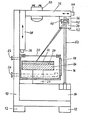
- This shows a device according to the invention, consisting of a frame 10 , which rests on air bearings 12 and carries a CW-CO 2 laser 14. Furthermore, the frame 1o a high vacuum chamber 16 is mounted, which open a lid according to the 18 is accessible from the outside and is bounded on the top by a window 1 0, for example of NaCl.
- the high vacuum chamber 16 has a vacuum connection 22 and an inlet opening 24 for protective gas.
- a table 26 is rotatably supported and rotatable by means of a drive motor 28.
- An interchangeable plate-shaped template 28 rests on the table, which has flat recessed, channel-shaped tracks on the top in the shape of the workpieces to be produced.
- the width and depth of these trough-shaped tracks are preferably less than about 1 mm, but may also be somewhat larger, if necessary.
- Metal powder for example made of copper, silver or another metal from which the workpiece is to be produced, is applied in a thin layer 3o to the surface of the template 28, at least in the region of one or more trough-shaped tracks. Such metal powders with a fine grain size of, for example, 1oo ⁇ are available.
- the thickness of the powder layer 3o and the depth of the trough-shaped tracks depend on the thickness of the workpieces to be produced.
- An aspherical mirror 34 is mounted and guided several times in a movable manner on a support arm 32 of the frame 10 extending over the high vacuum chamber 16.
- the support arm 32 itself can be moved vertically in the manner of a slide by means of a servomotor 36 along a vertical guide 38 on the frame 10.
- a mirror 34 receiving sealed housing 4 0, the bottom of which is formed by a window 42, by means of a servomotor 44 by way of a carriage on a longitudinal guide einlang Support arm 32 are moved.
- the mirror 34 can be pivoted about two intersecting horizontal axes by means of two servomotors 46 and 48.
- the support arm 32 of the frame 1o further carries an observation optical system 5 0, which is conveniently connected to a temperature measuring device.
- the observation optics allow the melting process in the high vacuum chamber to be observed through the window 2o, and the temperature measuring device connected to the observation optics 5o measures the temperature prevailing at the melting point on the basis of the radiation penetrating through the window 2o to the outside.
- the beam path of the laser beam 52 can also be selected differently than shown. While in the illustrated embodiment the deflecting and focusing optics with the aspherical mirror 34 are essentially perpendicular above the Beam exit of the laser 14 is arranged and the servomotor 44 is only used for the exact positioning of the mirror 34 before starting work, it could also be considered to move the housing 4o with the mirror 34 along the support arm 32 during the work and by means of the laser beam 52 of a controllable beam exit on the laser 14 so that the laser beam is aimed at the mirror 34 at all times.
- a pure deflecting mirror could also be used in conjunction with a focusing lens.
- the melting and molding process can be controlled. However, it is also possible to provide a control which uses the temperatures measured by the temperature measuring device in order to guide the focal point of the laser beam 52 along a trough-shaped path of the template 28 at an optimal path speed.
- the melting process will normally be carried out under a continuous flow of inert gas.
- the protective gas enters the high-vacuum chamber 16 via the inlet opening 24 and is sucked out of it again through the vacuum connection 22.
- the speed at which the focal point of the laser beam 52 moves on the surface of the stencil 28 can be between approximately 0.1 mm and approximately 100 mm per hour.
Landscapes
- Engineering & Computer Science (AREA)
- Chemical & Material Sciences (AREA)
- Materials Engineering (AREA)
- Manufacturing & Machinery (AREA)
- Mechanical Engineering (AREA)
- General Health & Medical Sciences (AREA)
- Toxicology (AREA)
- Health & Medical Sciences (AREA)
- Automation & Control Theory (AREA)
- Physics & Mathematics (AREA)
- Plasma & Fusion (AREA)
- Chemical Kinetics & Catalysis (AREA)
- Metallurgy (AREA)
- Organic Chemistry (AREA)
- Laser Beam Processing (AREA)
Applications Claiming Priority (2)
| Application Number | Priority Date | Filing Date | Title |
|---|---|---|---|
| DE3445613A DE3445613C1 (de) | 1984-12-14 | 1984-12-14 | Verfahren und Vorrichtung zur spanlosen Herstellung schmaler,laenglicher Werkstuecke aus Metall mittels Laserstrahls |
| DE3445613 | 1984-12-14 |
Publications (2)
| Publication Number | Publication Date |
|---|---|
| EP0184839A1 true EP0184839A1 (fr) | 1986-06-18 |
| EP0184839B1 EP0184839B1 (fr) | 1989-03-08 |
Family
ID=6252763
Family Applications (1)
| Application Number | Title | Priority Date | Filing Date |
|---|---|---|---|
| EP85115810A Expired EP0184839B1 (fr) | 1984-12-14 | 1985-12-11 | Procédé et dispositif pour la fabrication sans copeaux de pièces à usiner étroites et allongées en métal au moyen d'un rayon laser |
Country Status (2)
| Country | Link |
|---|---|
| EP (1) | EP0184839B1 (fr) |
| DE (1) | DE3445613C1 (fr) |
Families Citing this family (8)
| Publication number | Priority date | Publication date | Assignee | Title |
|---|---|---|---|---|
| DE3517132A1 (de) * | 1985-05-11 | 1986-11-13 | Jürgen 6074 Rödermark Wisotzki | Halbleiterelement mit einem elektrisch leitend mit ihm verbundenen mikroelement sowie verfahren zur herstellung der verbindung |
| JPH0730362B2 (ja) * | 1987-03-20 | 1995-04-05 | 株式会社日立製作所 | 電子部品及びその製造方法 |
| DE19853979A1 (de) * | 1998-11-23 | 2000-05-31 | Fraunhofer Ges Forschung | Vorrichtung und Verfahren zum Abtasten einer Objektfläche mit einem Laserstrahl, insbesondere zum selektiven Laser-Schmelzen |
| DE112004000301B4 (de) * | 2003-02-25 | 2010-05-20 | Panasonic Electric Works Co., Ltd., Kadoma-shi | Verfahren und Vorrichtung zur Herstellung eines dreidimensionalen Objekts |
| US7521652B2 (en) * | 2004-12-07 | 2009-04-21 | 3D Systems, Inc. | Controlled cooling methods and apparatus for laser sintering part-cake |
| DE102006014835A1 (de) * | 2006-03-30 | 2007-10-04 | Fockele, Matthias, Dr. | Vorrichtung zur Herstellung von Gegenständen durch schichtweises Aufbauen aus pulverförmigem Werkstoff |
| US20100155985A1 (en) | 2008-12-18 | 2010-06-24 | 3D Systems, Incorporated | Apparatus and Method for Cooling Part Cake in Laser Sintering |
| CN107931605B (zh) * | 2017-10-09 | 2021-01-29 | 太原理工大学 | 用于摩擦副表面微织构的3d打印制作方法 |
Citations (3)
| Publication number | Priority date | Publication date | Assignee | Title |
|---|---|---|---|---|
| US4177372A (en) * | 1976-05-26 | 1979-12-04 | Hitachi, Ltd. | Method and apparatus for laser zone melting |
| US4243867A (en) * | 1978-06-26 | 1981-01-06 | Caterpillar Tractor Co. | Apparatus for fusibly bonding a coating material to a metal article |
| US4464557A (en) * | 1981-11-23 | 1984-08-07 | Risbud Subhash H | Crystal growth in glasses and amorphous semiconductors |
-
1984
- 1984-12-14 DE DE3445613A patent/DE3445613C1/de not_active Expired
-
1985
- 1985-12-11 EP EP85115810A patent/EP0184839B1/fr not_active Expired
Patent Citations (3)
| Publication number | Priority date | Publication date | Assignee | Title |
|---|---|---|---|---|
| US4177372A (en) * | 1976-05-26 | 1979-12-04 | Hitachi, Ltd. | Method and apparatus for laser zone melting |
| US4243867A (en) * | 1978-06-26 | 1981-01-06 | Caterpillar Tractor Co. | Apparatus for fusibly bonding a coating material to a metal article |
| US4464557A (en) * | 1981-11-23 | 1984-08-07 | Risbud Subhash H | Crystal growth in glasses and amorphous semiconductors |
Also Published As
| Publication number | Publication date |
|---|---|
| EP0184839B1 (fr) | 1989-03-08 |
| DE3445613C1 (de) | 1985-07-11 |
Similar Documents
| Publication | Publication Date | Title |
|---|---|---|
| DE19953000C2 (de) | Verfahren und Einrichtung zur schnellen Herstellung von Körpern | |
| DE19935274C1 (de) | Vorrichtung und Verfahren zur Herstellung von Bauteilen aus einer Werkstoffkombination | |
| DE19511772C2 (de) | Vorrichtung und Verfahren zum Herstellen eines dreidimensionalen Objektes | |
| EP1137504B1 (fr) | Chambre de processus pour la fusion selective par laser | |
| EP1133377B1 (fr) | Dispositif et procede de balayage de la surface d'un objet a l'aide d'un faisceau laser | |
| DE3785745T2 (de) | Verfahren zum behandeln von grossen gusseisenmatrizen, insbesondere zum pressverformen von metallblechen fuer fahrzeuge, und vorrichtung zum durchfuehren des verfahrens. | |
| EP1332039B1 (fr) | Dispositif de frittage, de gravure et/ou d'ecriture par l'intermediaire de rayonnement electromagnetique en faisceau et procede d'utilisation du dispositif | |
| DE69124232T2 (de) | Laser und laserschweissenverfahren | |
| EP1173304B1 (fr) | Procede de production d'un composant cylindrique, partiellement cylindrique ou cylindrique creux dont la surface est alliee | |
| EP0491075B1 (fr) | Procédé de préparation d'une aube de turbine en alliage à base de titane | |
| DE69104326T2 (de) | Gerät zur Laserbearbeitung. | |
| EP0223058A1 (fr) | Procédé de soudage du support métallique d'un appareil catalytique | |
| EP0184839B1 (fr) | Procédé et dispositif pour la fabrication sans copeaux de pièces à usiner étroites et allongées en métal au moyen d'un rayon laser | |
| EP0558135B1 (fr) | Procédé pour engendrer un dessin dans la surface d'une pièce d'oeuvre | |
| EP1404484B1 (fr) | Outil de coupe en forme de bande | |
| DE3801068A1 (de) | Verfahren und vorrichtung zum abtragen mittels gebuendelter energiestrahlen | |
| DD268421A5 (de) | Verfahren und vorrichtung zum entfernen von beschichtungen mit einem laserstrahl | |
| DE19520149B4 (de) | Vorrichtung zur Herstellung, Verfahren zur Herstellung und Verwendung einer Beschichtung auf einem Bauteil | |
| DE3626808C2 (fr) | ||
| EP0336335B1 (fr) | Procédé de fabrication de matières céramiques amorphes et d'alliages amorphes | |
| DE10215999A1 (de) | Verfahren zur Herstellung von faserverstärktem Halbzeug in Form von Metallbändern, Metallblechen oder dergleichen sowie Vorrichtung zur Durchführung des Verfahrens | |
| DE3541584C2 (fr) | ||
| DE4415783A1 (de) | Verfahren zur Freiformherstellung von Werkstücken | |
| DE3300576C2 (de) | Verfahren und Vorrichtung zur Herstellung eines optischen Bauteils, insbesondere eines Metallreflektors | |
| EP1331058A1 (fr) | Méthode et dispositif pour réaliser un cordon de soudure brasé ou soudé à l'aide d'un laser |
Legal Events
| Date | Code | Title | Description |
|---|---|---|---|
| PUAI | Public reference made under article 153(3) epc to a published international application that has entered the european phase |
Free format text: ORIGINAL CODE: 0009012 |
|
| AK | Designated contracting states |
Kind code of ref document: A1 Designated state(s): FR GB |
|
| 17P | Request for examination filed |
Effective date: 19861217 |
|
| 17Q | First examination report despatched |
Effective date: 19880328 |
|
| GRAA | (expected) grant |
Free format text: ORIGINAL CODE: 0009210 |
|
| AK | Designated contracting states |
Kind code of ref document: B1 Designated state(s): FR GB |
|
| GBT | Gb: translation of ep patent filed (gb section 77(6)(a)/1977) | ||
| ET | Fr: translation filed | ||
| PLBE | No opposition filed within time limit |
Free format text: ORIGINAL CODE: 0009261 |
|
| STAA | Information on the status of an ep patent application or granted ep patent |
Free format text: STATUS: NO OPPOSITION FILED WITHIN TIME LIMIT |
|
| 26N | No opposition filed | ||
| PGFP | Annual fee paid to national office [announced via postgrant information from national office to epo] |
Ref country code: FR Payment date: 19930601 Year of fee payment: 8 |
|
| PGFP | Annual fee paid to national office [announced via postgrant information from national office to epo] |
Ref country code: GB Payment date: 19930608 Year of fee payment: 8 |
|
| PG25 | Lapsed in a contracting state [announced via postgrant information from national office to epo] |
Ref country code: GB Effective date: 19931211 |
|
| GBPC | Gb: european patent ceased through non-payment of renewal fee |
Effective date: 19931211 |
|
| PG25 | Lapsed in a contracting state [announced via postgrant information from national office to epo] |
Ref country code: FR Effective date: 19940831 |
|
| REG | Reference to a national code |
Ref country code: FR Ref legal event code: ST |