EP0184850A2 - Ferrure de charnière - Google Patents
Ferrure de charnière Download PDFInfo
- Publication number
- EP0184850A2 EP0184850A2 EP85115885A EP85115885A EP0184850A2 EP 0184850 A2 EP0184850 A2 EP 0184850A2 EP 85115885 A EP85115885 A EP 85115885A EP 85115885 A EP85115885 A EP 85115885A EP 0184850 A2 EP0184850 A2 EP 0184850A2
- Authority
- EP
- European Patent Office
- Prior art keywords
- fitting according
- bearing
- hinge fitting
- fastening part
- hinge
- Prior art date
- Legal status (The legal status is an assumption and is not a legal conclusion. Google has not performed a legal analysis and makes no representation as to the accuracy of the status listed.)
- Granted
Links
Images


Classifications
-
- E—FIXED CONSTRUCTIONS
- E05—LOCKS; KEYS; WINDOW OR DOOR FITTINGS; SAFES
- E05D—HINGES OR SUSPENSION DEVICES FOR DOORS, WINDOWS OR WINGS
- E05D7/00—Hinges or pivots of special construction
- E05D7/04—Hinges adjustable relative to the wing or the frame
-
- E—FIXED CONSTRUCTIONS
- E05—LOCKS; KEYS; WINDOW OR DOOR FITTINGS; SAFES
- E05D—HINGES OR SUSPENSION DEVICES FOR DOORS, WINDOWS OR WINGS
- E05D5/00—Construction of single parts, e.g. the parts for attachment
- E05D5/02—Parts for attachment, e.g. flaps
-
- E—FIXED CONSTRUCTIONS
- E05—LOCKS; KEYS; WINDOW OR DOOR FITTINGS; SAFES
- E05Y—INDEXING SCHEME ASSOCIATED WITH SUBCLASSES E05D AND E05F, RELATING TO CONSTRUCTION ELEMENTS, ELECTRIC CONTROL, POWER SUPPLY, POWER SIGNAL OR TRANSMISSION, USER INTERFACES, MOUNTING OR COUPLING, DETAILS, ACCESSORIES, AUXILIARY OPERATIONS NOT OTHERWISE PROVIDED FOR, APPLICATION THEREOF
- E05Y2900/00—Application of doors, windows, wings or fittings thereof
- E05Y2900/40—Application of doors, windows, wings or fittings thereof for gates
Definitions
- the invention relates to a hinge fitting with the features of the preamble of claim 1.
- Such a door fitting is known from DE-OS 22 05 339, which has the task of improving the adaptability between the door frame and the door.
- a bearing element that can be locked in the desired position and that has a threaded bore that runs transversely to its pivot axis and into which a threaded bolt that is oriented transversely to the hinge pin and rigidly connected to the supporting part of the door hinge engages. This makes it possible not only to adjust the height of the supporting part, but also to pivot the bearing element to improve the adaptation options.
- This previously known hinge fitting is disadvantageous insofar as it can only be assembled with complex means (by welding on a metal frame), an adjustment of the protruding length of the block when the door leaf is hung in is not possible at all, and thus the adjustment can only be made by repeatedly hanging and unhooking the door can be made.
- the swivel range of the block is very narrow.
- an adjustable anchorage of door and window hinges which consists of a hollow screw which is provided with an internal and an external thread.
- a block pin engages in the inner thread
- the outer thread engages with * an internal thread in the door leaf or Door frame is attached.
- a pivoting movement of the fitting parts about an axis parallel to the hinge axis is not possible with this device, furthermore, the multi-threaded version of the hollow screw is expensive to manufacture and in particular also requires an internal thread in the part which stores the hollow screw.
- a door hanger emerges that has a swivel block that is attached to the goal post on the one hand pivotable and height-adjustable and on the other hand is provided with an eccentric that rotates on the swivel block and with a pivot point of the gate-forming pivot pin is provided, in which the gate is hung.
- the invention has for its object to provide a hinge fitting for pivotable about a hinge axis flat parts such as gates, gate leaves or the like.
- the adjustment swivel movement is blocked, the swiveling of the gate leaf or the like relative to the hinge fitting takes place exclusively along the hinge axis.
- Such a swivel adjustment is advantageous in that, in the case of warped doors, twisting one of the hinge clamps or eyebolts from the normally aligned position with other block pegs on the one hand can effectively compensate for the self-warping of doors, but on the other hand also an increase in the door / gate leaf in one or the other direction can be achieved during the swiveling-up movement, as is the case, for example, with rising courtyard entrances. Like. is required.
- the person installing or adjusting the fitting has a high degree of flexibility available to effectively counter all assembly and adjustment difficulties that occur.
- the combination of features defined in claim 1 makes it possible to move the hinge axis as it were on circular paths with different radii and to fix it there.
- the radius adjustment is carried out by screwing the extension arm into the fastening part to a greater or lesser extent, the circular adjustment by pivoting the fastening part itself.
- the pivoting area of the part fastened to the hinge can be adjusted, as it were, by interposing a further joint between the post, frame or wall and the hinge axis.
- a gate wing that opens to the inside of the property over a swivel angle of 180 °, for example, by defining the cantilever arm rotational positions so that it does not interfere with the property in the fully open position and, for example, the driving or parking options in the area Restricted property.
- the screw thread of the boom does not engage directly in a thread of the fastening part, but rather is indirectly fastened in the fastening part via a sleeve-like intermediate part which is rotatably mounted in the fastening part. This makes it possible for the length of the cantilever arm (of the Klobens or the eye screw) until the gate in the lock area assumes exactly the desired position.
- the intermediate part protrudes from the fastening part at its end facing the pivot bearing and is provided with an attachment for engaging a tool, for example a specially shaped wrench or the like.
- the fastening part without the interposition of further fastening elements, as it were, as screw-on pliers in the pre-assembly state on round fence posts and the like.
- the intermediate part is contained in a bearing section protruding from the ends of the pliers.
- a mounting plate can, for example, be fastened to posts with a rectangular or square cross-section; a special plier-like fitting is provided, for example, for posts that have a non-round, for example triangular or hexagonal, cross-sectional shape.
- a length-adjustable pivot offset compensation piece can be arranged, which i. w. consists of a threaded rod and end fittings, the first end fitting is rotatably mounted on the block pin or on the bearing eye and the second end fitting engages and is fixed at a constant angular position on the bearing element of the surface part.
- this fulcrum offset compensation piece With the help of this fulcrum offset compensation piece and with the simultaneous use of the adjustable fitting, it is possible to set the ascending pivoting movement precisely and precisely, for example when the gate is rising, without having to put up with the fact that the gate gapes in the closed position or hangs obliquely on its hinges .
- the length of the cantilever arm, the length of the pivot offset offset piece and the protruding angle of the cantilever arm can be varied (more or less at the same time) with the door suspended until all parameters ensure an optimal pivoting and closing function of the door.
- the threaded rod for optimizing the distance between the end fittings is provided with two opposing threads and a shape for engaging a tool for rotation when the surface part is suspended.
- pivot offset compensating piece can be found in claims 18 and 19, claim 20 becomes more important if pivot point offset compensating pieces of great length are used, which would possibly lead to a buckling load on the pin journals or the like, which would result from the provision the swivel joint of the cantilever arm and / or the threaded rod is avoided.
- the hinge fitting is used to hang flat parts pivotable about a hinge axis, such as door or gate leaves, shutters, box covers, trap doors and the like.
- a hinge axis such as door or gate leaves, shutters, box covers, trap doors and the like.
- Such flat parts which are not shown in the drawing figures, are either attached to a frame part (e.g. a box lid or a room door), a post (e.g. a fence gate) or a wall and have one as Rotary bearing serving suspension, for example a block, as shown in Fig. 1 a).
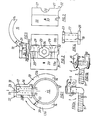
- a block 1 consists of a cantilever arm 2 and a block pin 3 fastened thereon approximately at right angles, by means of which the hinge axis 4 is fixed.
- the flat, swiveling part (in the following for short door leaf) has a sleeve-like Swivel part 1 5, which overlaps the block pin 3 in the manner of a sleeve and is also shown schematically in Fig. 1 a).
- an eyebolt 6 can also be provided, which likewise has a cantilever arm 7 and has a bearing eye 8 at one end through which a bearing pin 9 can be passed, on which the pivoting part 110 is rotatably supported in the form of perforated legs projecting from the door leaf is (Fig. 1 b).
- Both the cantilever arm 2 and the cantilever arm 7 are each provided with a screw thread 11 which is screwed into a counter thread which is arranged on the frame part, the post or the wall.
- the cantilever arm 2, 7 of the block 1 or the eye screw 6 is arranged on a fastening part which can be pivoted about a hinge axis 4 parallel to the hinge axis 4 in the preassembled state and can be screwed into it by means of its screw thread 11.
- the fastening part 13 has a plier-like shape for this purpose, the pliers ends 14 forming between them an generally circular recess 15 for gripping the post 12 with a round cross section, and a bearing section 16 projecting from the pliers ends 14 receiving a sleeve-like intermediate part 17, which is provided with an internal thread 18 which receives the screw thread 11.
- the intermediate part 17 is rotatably mounted in the fastening part 13 about its longitudinal axis 19 and is secured against displacement in the axial direction by an edge projection 20 which engages in a groove 21 of the fastening part 13.
- the intermediate part is also pending its end 22 facing the pivot bearing (block pin 3) out of the fastening part 13 and has a nut-like extension for engaging a tool.
- the rotary movement of the intermediate part 17 can be determined by a grub screw 24.
- the fastening part is divided in the middle into two halves by a parting joint 25 running parallel to the longitudinal direction of the post such that the intermediate part 17 lies in trough-like, semicircular recesses 26 of the parting joint contact surfaces 27.
- the parting line 25 opens in the final assembly position, including an acute angle 28 towards the post 12, so that the halves 13 a, 13 b of the fastening part 13 can clasp the outer wall of the post in the final assembly position under a tight fit, so that the clamping force is exerted by clamping screws 29, which Push the fastening part through in the transition area of the bearing section 16 into the pliers area 30.
- the parting line 25 is covered by guide projections 32 formed integrally with one half (13 a, 13 b) of the fastening part.
- a holding screw 33 is also arranged in the pliers area of the fastening part 13, by means of which the fastening part 13 can be secured against rotation on the post 12.
- FIGS. 6-12 Another type of design and mounting of the fastening part is shown in FIGS. 6-12.
- the fastening part as a cylindrical body 40 can be rotated between holding projections on a mounting plate 41 (FIG. 6) or a pliers type attached mounting bracket 42 (Fig. 12) for posts and strips of any cross-sectional shape, the mounting bracket also has a plier-like shape and with its pliers ends 43 encloses a recess 44 which corresponds in cross-sectional shape to the cross-sectional shape of the support part, thus square, hexagonal, triangular o. dg1. is trained.
- the mounting bracket 42 is also formed in two parts with a parting line 45 and can be fastened to the post or frame by means of clamping screws 46.
- a bearing box 47 is provided on the mounting plate 41 or the mounting fitting 42 for receiving the cylindrical body 40, the interior 48 of which forms a bearing recess for the cylindrical body 40, which can be rotated about its cylinder axis 50 in the bearing recess.
- a bore 51 (FIG. 10) is provided within the cylindrical body 40 for receiving the intermediate part 52, which is designed in accordance with the intermediate part 17 of the embodiment described above.
- the storage box 47 has on its box front 53 facing away from the pliers ends 43 a passage opening 54 which extends laterally from the box front 53 into the area of the mounting plate 41 or the mounting bracket 42 and thus pivots the cylindrical body with the clamp or eyebolt attached to it enables into the side area (arrow "S" in Fig. 10 and 11).
- the cylindrical body 40 is divided approximately centrally at right angles to its cylinder axis 50, the axis of the bore 51 for receiving the intermediate part 52 lies in the joint area 55 of the cylindrical body 40.
- the bearing box 47 is formed in one piece with the associated pliers halves or the mounting plate
- the bearing box 47 is formed as a separate part with respect to the mounting plate 41.
- the bearing box 47 For mutual attachment, he has in this case on his wall-side box back 56 on an outwardly projecting connecting flange 57, the bearing box 47 itself extends through a holding recess 58 of the mounting plate 41 such that the connecting flange 57 in a holding recess 58 i. w. surrounding flange recess 59 rests on the rear side 60 of the mounting plate 41 facing the wall or the post.
- the storage box 47 is provided on its box back 56 with a separate cover plate 61, on the inside 62 of which the cylindrical body 40 rests (FIG. 11).
- the fastening part is mounted in the form of a cylindrical body 40 within a storage box. It is also possible to design the fastening part modified and z. B. between two mounting plates protruding from the mounting plate or the mounting bracket and fastened in this by means of a pivot. Such an embodiment is not shown in the drawing figures.
- FIGS. 13-18 relate to a length-adjustable pivot offset compensation piece 70, which i. w. consists of a threaded rod 71 and end fittings 72, 73, the first end fitting 72 being rotatably mounted in the disassembled state on the block pin 3 or on the bearing eye 8 and the second end fitting 73 on the bearing element (pivoting part 1 5 or 10) of the flat part at a constant angular position l attacks and is attached.
- a length-adjustable pivot offset compensation piece 70 which i. w. consists of a threaded rod 71 and end fittings 72, 73, the first end fitting 72 being rotatably mounted in the disassembled state on the block pin 3 or on the bearing eye 8 and the second end fitting 73 on the bearing element (pivoting part 1 5 or 10) of the flat part at a constant angular position l attacks and is attached.
- pivot point offset compensation piece compensates for the desired rotational offset necessary for lifting a gate leaf between the clamps fastened, for example, to a gate post with the fitting described above, so that the bore 74 of the second end fitting is aligned with the block pin 3, which is not provided with the compensating piece. If the door is swung open, the rotation takes place around the bore 75 of the first end fitting, so that when the door is fully open, the door edge provided with the pivot point offset compensation piece 70 moves away from the position which it occupies in the closed position by an amount of 2 ⁇ A is achieved in Figure 13. If, for example, the lower hinge fitting of a garage door is provided with the pivot point offset compensation piece 70, the lock edge of the door is raised when it is swung open.
- the threaded rod 71 is provided with two opposing threads 76, 77 and an Allen key 78 for engaging an appropriately designed tool for rotating the threaded rod. This allows the distance "A" to be varied when the gate leaves are narrow.
- the second end fitting 73 overlaps the sleeve-like bearing element (swivel part 5, 10) fastened to the surface part and is with a clamping bolt 79 passing through the bore of the bearing element 5, 10 at a constant angular position on the latter attached.
- the threaded rod 71 passes through the end fittings 72, 73 in the threaded recess 80, 81 approximately at right angles to the longitudinal axes of the recesses 74, 75 for the block pin or the clamping screw.
- the cantilever arm 2, 7 and the threaded rod 71 are provided with a pivot joint 92, 93, the pivot axis 94 of which is perpendicular to the longitudinal axes of the cantilever arm or the threaded rod and at the same time perpendicular to the longitudinal axes of the recess for the block pin or the tensioning screw (Fig. 18 a - c).
Landscapes
- Engineering & Computer Science (AREA)
- Mechanical Engineering (AREA)
- Hinges (AREA)
Priority Applications (1)
| Application Number | Priority Date | Filing Date | Title |
|---|---|---|---|
| AT85115885T ATE37926T1 (de) | 1984-12-14 | 1985-12-12 | Scharnierbeschlag. |
Applications Claiming Priority (2)
| Application Number | Priority Date | Filing Date | Title |
|---|---|---|---|
| DE8436622U DE8436622U1 (de) | 1984-12-14 | 1984-12-14 | Scharnierbeschlag |
| DE8436622U | 1984-12-14 |
Publications (3)
| Publication Number | Publication Date |
|---|---|
| EP0184850A2 true EP0184850A2 (fr) | 1986-06-18 |
| EP0184850A3 EP0184850A3 (en) | 1986-12-17 |
| EP0184850B1 EP0184850B1 (fr) | 1988-10-12 |
Family
ID=6773758
Family Applications (1)
| Application Number | Title | Priority Date | Filing Date |
|---|---|---|---|
| EP85115885A Expired EP0184850B1 (fr) | 1984-12-14 | 1985-12-12 | Ferrure de charnière |
Country Status (3)
| Country | Link |
|---|---|
| EP (1) | EP0184850B1 (fr) |
| AT (1) | ATE37926T1 (fr) |
| DE (2) | DE8436622U1 (fr) |
Family Cites Families (7)
| Publication number | Priority date | Publication date | Assignee | Title |
|---|---|---|---|---|
| US2182548A (en) * | 1938-04-18 | 1939-12-05 | Charles W Bash | Gate hinge |
| GB618725A (en) * | 1946-11-20 | 1949-02-25 | Phillip Harwood | Improvements in an adjustable mounting for a pin for hanging a gate or door |
| US2683279A (en) * | 1951-11-07 | 1954-07-13 | Elmer F Okerlund | Adjustable and reversible hinge |
| DE1945125U (de) * | 1966-06-24 | 1966-08-25 | Horst Thomas Drahtzaunbau & Ba | Torgehaenge. |
| DE2039307A1 (de) * | 1970-08-07 | 1972-02-10 | Bayerische Motoren Werke Ag | Scharnier fuer Kraftfahrzeugtueren |
| US4079481A (en) * | 1977-01-31 | 1978-03-21 | Cacicedo Paulino A | Double-hinged gate hinge |
| CH651100A5 (de) * | 1981-05-12 | 1985-08-30 | Walter Hauptmann | Scharnier zur beweglichen verankerung von tueren und fenstern. |
-
1984
- 1984-12-14 DE DE8436622U patent/DE8436622U1/de not_active Expired
-
1985
- 1985-12-12 AT AT85115885T patent/ATE37926T1/de not_active IP Right Cessation
- 1985-12-12 DE DE8585115885T patent/DE3565571D1/de not_active Expired
- 1985-12-12 EP EP85115885A patent/EP0184850B1/fr not_active Expired
Also Published As
| Publication number | Publication date |
|---|---|
| ATE37926T1 (de) | 1988-10-15 |
| DE8436622U1 (de) | 1985-12-12 |
| EP0184850B1 (fr) | 1988-10-12 |
| EP0184850A3 (en) | 1986-12-17 |
| DE3565571D1 (en) | 1988-11-17 |
Similar Documents
| Publication | Publication Date | Title |
|---|---|---|
| DE4219681C2 (de) | Einstellbares Abhebescharnier | |
| DE2723850C2 (de) | Möbelscharnier | |
| DE602004002173T2 (de) | Einrichtung für eine höheneinstellbare Halterung eines Tores | |
| DE102017100270B3 (de) | Türband sowie Zimmertür | |
| DE29922023U1 (de) | Baugruppe mit einem Band für Türen, Fenster o.dgl. | |
| EP1223276B1 (fr) | Charnière pour portes, fenêtres et similaires | |
| WO1999015749A1 (fr) | Ferrure pour montage pivotant d'un vantail de fenetre ou de porte | |
| DE10313961B4 (de) | Verstellbares Band, insbesondere für Dusch- und/oder Glastüren | |
| DE10148935A1 (de) | Beschlag für Schiebetüren | |
| DE3539576C2 (fr) | ||
| DE19943567C2 (de) | Befestigungsvorrichtung für eine Duschabtrennung | |
| EP0184850B1 (fr) | Ferrure de charnière | |
| DE202009003119U1 (de) | Beschlag für die Befestigung einer Duschtür | |
| EP0487825B1 (fr) | Ferrure arrangée en feuillure pour aile pivotante, en particulier pour aile oscillo-battante, de fenêtre ou portes | |
| DE2758333C2 (de) | Beschlag für Flügel von Fenstern, Türen o.dgl., insbesondere Drehkipp- Flügel | |
| EP4045745B1 (fr) | Palier d'angle | |
| DE3001070A1 (de) | Eckgelenk fuer drehkippfenster, -tueren o.dgl. | |
| EP1560996A1 (fr) | Systeme d'armatures pour portes en verre | |
| DE3445598C2 (fr) | ||
| EP1038486B1 (fr) | Jeu de pièces pour cloisons de douches | |
| DE10103646A1 (de) | Hebebeschlag für einen an einem Torpfosten befestigten Torrahmen oder Türflügel | |
| DE8111079U1 (de) | Ecklager fuer fluegel von fenstern, tueren od. dgl. | |
| DE3203321A1 (de) | Fluegelrahmenseitiges ecklager fuer fenster, insbesondere drehkippfenster | |
| EP4108877B1 (fr) | Charnière pour une porte, une fenêtre ou un composant similaire | |
| DE19940132C2 (de) | Gelenkband |
Legal Events
| Date | Code | Title | Description |
|---|---|---|---|
| PUAI | Public reference made under article 153(3) epc to a published international application that has entered the european phase |
Free format text: ORIGINAL CODE: 0009012 |
|
| AK | Designated contracting states |
Kind code of ref document: A2 Designated state(s): AT BE CH DE FR GB IT LI LU NL SE |
|
| PUAL | Search report despatched |
Free format text: ORIGINAL CODE: 0009013 |
|
| AK | Designated contracting states |
Kind code of ref document: A3 Designated state(s): AT BE CH DE FR GB IT LI LU NL SE |
|
| 17P | Request for examination filed |
Effective date: 19870319 |
|
| 17Q | First examination report despatched |
Effective date: 19880119 |
|
| GRAA | (expected) grant |
Free format text: ORIGINAL CODE: 0009210 |
|
| AK | Designated contracting states |
Kind code of ref document: B1 Designated state(s): AT BE CH DE FR GB IT LI LU NL SE |
|
| PG25 | Lapsed in a contracting state [announced via postgrant information from national office to epo] |
Ref country code: SE Effective date: 19881012 Ref country code: NL Effective date: 19881012 Ref country code: IT Free format text: LAPSE BECAUSE OF FAILURE TO SUBMIT A TRANSLATION OF THE DESCRIPTION OR TO PAY THE FEE WITHIN THE PRESCRIBED TIME-LIMIT;WARNING: LAPSES OF ITALIAN PATENTS WITH EFFECTIVE DATE BEFORE 2007 MAY HAVE OCCURRED AT ANY TIME BEFORE 2007. THE CORRECT EFFECTIVE DATE MAY BE DIFFERENT FROM THE ONE RECORDED. Effective date: 19881012 Ref country code: GB Free format text: LAPSE BECAUSE OF NON-PAYMENT OF DUE FEES Effective date: 19881012 Ref country code: FR Free format text: THE PATENT HAS BEEN ANNULLED BY A DECISION OF A NATIONAL AUTHORITY Effective date: 19881012 Ref country code: BE Effective date: 19881012 |
|
| REF | Corresponds to: |
Ref document number: 37926 Country of ref document: AT Date of ref document: 19881015 Kind code of ref document: T |
|
| REF | Corresponds to: |
Ref document number: 3565571 Country of ref document: DE Date of ref document: 19881117 |
|
| PG25 | Lapsed in a contracting state [announced via postgrant information from national office to epo] |
Ref country code: LU Free format text: LAPSE BECAUSE OF NON-PAYMENT OF DUE FEES Effective date: 19881231 |
|
| EN | Fr: translation not filed | ||
| NLV1 | Nl: lapsed or annulled due to failure to fulfill the requirements of art. 29p and 29m of the patents act | ||
| GBV | Gb: ep patent (uk) treated as always having been void in accordance with gb section 77(7)/1977 [no translation filed] | ||
| PLBE | No opposition filed within time limit |
Free format text: ORIGINAL CODE: 0009261 |
|
| STAA | Information on the status of an ep patent application or granted ep patent |
Free format text: STATUS: NO OPPOSITION FILED WITHIN TIME LIMIT |
|
| PG25 | Lapsed in a contracting state [announced via postgrant information from national office to epo] |
Ref country code: DE Effective date: 19890901 |
|
| 26N | No opposition filed | ||
| PG25 | Lapsed in a contracting state [announced via postgrant information from national office to epo] |
Ref country code: AT Effective date: 19891212 |
|
| PG25 | Lapsed in a contracting state [announced via postgrant information from national office to epo] |
Ref country code: LI Effective date: 19891231 Ref country code: CH Effective date: 19891231 |
|
| REG | Reference to a national code |
Ref country code: CH Ref legal event code: PL |