EP0184858B1 - Bottom structure of a boat - Google Patents
Bottom structure of a boat Download PDFInfo
- Publication number
- EP0184858B1 EP0184858B1 EP85115936A EP85115936A EP0184858B1 EP 0184858 B1 EP0184858 B1 EP 0184858B1 EP 85115936 A EP85115936 A EP 85115936A EP 85115936 A EP85115936 A EP 85115936A EP 0184858 B1 EP0184858 B1 EP 0184858B1
- Authority
- EP
- European Patent Office
- Prior art keywords
- boat
- keel
- line
- bottom structure
- steps
- Prior art date
- Legal status (The legal status is an assumption and is not a legal conclusion. Google has not performed a legal analysis and makes no representation as to the accuracy of the status listed.)
- Expired - Lifetime
Links
- 230000000630 rising effect Effects 0.000 claims description 23
- 230000000063 preceeding effect Effects 0.000 claims 1
- XLYOFNOQVPJJNP-UHFFFAOYSA-N water Substances O XLYOFNOQVPJJNP-UHFFFAOYSA-N 0.000 description 29
- 230000007423 decrease Effects 0.000 description 8
- 230000006978 adaptation Effects 0.000 description 5
- 230000000694 effects Effects 0.000 description 4
- 230000000295 complement effect Effects 0.000 description 2
- 238000010276 construction Methods 0.000 description 2
- 238000006073 displacement reaction Methods 0.000 description 1
- 230000002349 favourable effect Effects 0.000 description 1
- 230000003116 impacting effect Effects 0.000 description 1
Images
Classifications
-
- B—PERFORMING OPERATIONS; TRANSPORTING
- B63—SHIPS OR OTHER WATERBORNE VESSELS; RELATED EQUIPMENT
- B63B—SHIPS OR OTHER WATERBORNE VESSELS; EQUIPMENT FOR SHIPPING
- B63B1/00—Hydrodynamic or hydrostatic features of hulls or of hydrofoils
- B63B1/02—Hydrodynamic or hydrostatic features of hulls or of hydrofoils deriving lift mainly from water displacement
- B63B1/04—Hydrodynamic or hydrostatic features of hulls or of hydrofoils deriving lift mainly from water displacement with single hull
- B63B1/042—Hydrodynamic or hydrostatic features of hulls or of hydrofoils deriving lift mainly from water displacement with single hull the underpart of which being partly provided with channels or the like, e.g. catamaran shaped
Definitions
- the present invention relates to a bottom structure of a boat as defined in the introductory part of claim 1.
- GB-A 1 483 133 discloses a boat hull having a V-shaped bottom provided with a plurality of smoothly curved steps formed in the bottom. Each step terminating at its inner end at an angle of about 90° to the keel line and at a respective point spaced from the keel line. At least some of the steps, including the after-most step, terminating at their outer ends substantially at the chine line. The steps being so forwardly curved that the direction of water flowing immediately below the bottom of the hull, when the hull is planing on the water is substantially perpendicular to the steps.
- US 3 331 347 discloses a bottom structure of a planing boat, in which from 2 to 4 consecutive transverse steps on both halfs of the bottom are formed in order to minimize the resistance of water.
- the boat when planing, rises due to the effect of the steps so that the wet surface decreases.
- the biggest drawback in the bottom structures mentioned above is that the impacts of water are felt hard.
- the stepped bottom structure brought up in the publication FI 750 133 includes several curved steps, in which the angle of the step has been fitted in each part of the bottom according to the presumed flow of water.
- the step surfaces are smooth the flow pattern lines of water are curved, at which the steps are formed so that the direction of the flow of water as the boat is planing is essentially perpendicular to as large a portion of the step as possible. This results in a large number of steps and a complicated structure.
- US-A 2 039 586 discloses a boat of the planning or semi-planning type of which can have a single transverse step separating 2 major planing areas.
- the bow portion of the boat is formed of a series of smaller planing surfaces symmetrically arranged in complementary relation on opposite side of the keel and extending diagonally and longitudinally of the boat, each of such planing surfaces being separated from the next adjacent planing surface by an upward jog, except at the rearward end of the major planning areas.
- the jogs are constructed as straight edges.
- US-A 3 450 085 discloses a hydroplane boat hull having a bottom structure on which pairs of triangularly shaped flow separator devices are arranged on opposite sides of the longitudinal plane of symmetry of said hull. Said devices extends from adjacent of a chine aft which chine extends generally horizontally from the stem to the stern of the boat.
- the flow separator devices are splayed in complementary relationship to said plane of symmetry and converging aft. Pairs of devices progressively increases in width aft in plan view and progressively diminishes in length aft. The most aft pair of devices is substantially greater in width in plan view than any other pair and the pairs of devices are spaced at progressively greater distances aft from said plane of symmetry.
- These flow separator devices are functionally similar to rising laths.
- An object of the invention is to obviate the drawbacks mentioned above. Especially the object of the invention is to bring about a bottom structure of a boat which structure has good handling-characteristics in various circumstances, good loading properties and which is economical as well as less power demanding.
- the object of the present invention is solved by a bottom structure of a boat according to the invention, having the feature of the characterizing part of claim 1.
- the invention is based upon that by the right form of the stepped structure and in one adaptation by the use of rising laths the water surging sideways beneath the bottom can be bent back below the bottom to act as a load bearing element by utilizing pressure differences.
- the stepped structure forms in this case a multiple step accelerator, in which the flowrate of water increases significantly.
- the flow beneath the bottom is aimed to be kept in contact with the bottom and not separated from it as in all previous variations of stepped structures of the bottom.
- the flow can be maintained essentially in contact with the bottom, vortexes and fizzes, small air bubbles, which decrease the friction between the bottom of the boat and water, are formed near the hull due to the merit of the steps and the effect of the underpressure.
- the number of the steps in the bottom according to the invention is from 2 to 4, preferably 3.
- the bottom structure includes preferably rising laths which are not known in connection with previous stepped structures. On both halfs of the bottom, 2 to 6 rising laths have been included, preferably 3 to 5.
- the rising laths are fitted in "the wrong way” with respect to the prior art i.e. so that the steeper and narrower part of the surface of the lath is on the side of the keel.
- the rising laths effectively prevent the water from flowing outwards and the apparent bonyancy of the boat is better.
- the mainly straight edges of the steps form angles with the keel line of the boat. These angles vary from 20 ° to 60° depending upon the type of the boat.
- the ends of the steps nearby the keel begin at a small distance apart from the keel so that a mainly smooth area is left on both sides of the keel of the boat. This area doesn't include steps and extends along the whole length of the boat, which prevents cavitation and ensures smooth running for the propeller.
- the rising laths prevent the water from flowing sideways and the underpressure formed by the step construction in the space behind the step causes the flow of water towards the keel.
- the step is formed so that the end of the step near the keel is mainly parallel to the keel at a distance apart from the keel, and the end near the side of the bottom is mainly parallel to the side and at a distance apart from the side.
- the distance mentioned above is from 5 to 20 % preferably 10 % of width of the bottom between the keel line and the edge.
- the hight of the ends changes evenly from the rare towards the bow of the boat so that the ends begin smoothly from the plane of the base surface and increase evely in hight towards the front and turn circularly in order to form the edge of the step at the front part.
- the width of the edge of the step changes uniformly from the middle part towards the side of the bottom. In this manner the mainly vertical edge and the ends of the step from an edge of the step structure which rises and decreases evenly.
- the edge of step is at its highest near the circular point of convergence of the edge and the end near the side of the bottom.
- the steps are conveniently formed so that the steps can be imagined as rising upwards from the base surface of the bottom.
- the angle of impact increases.
- the angle of impact increases, it won't cause an increase in the hardness of the bottom, because at the same time the V-angle of the bottom increases, which on the other hand softens the passage of the boat through water.
- the rising laths curve suitably at the bow of the boat in a direction mainly parallel to the seam line towards the keel line and extend to the keel. In this manner the rising laths direct the bow splashes under the boat and smoothen the passage of the boat.
- the stepped surfaces are mainly parallel. In another adaptation the stepped surfaces are divergent so that the angle of impact is biggest at the raremost step and smallest at the step farthest to front.
- the step structure in accordance with the invention has been placed in a sailing boat or other boat with a proper keel.
- the bottom of the boat according to the invention has also the presented favourable effects upon the properties of boats and ships which have a displacing hull structure.
- a change in the flow of water under the bottom of the boat is achieved by the bottom structure according to the invention so that all of the water flows out mainly from the rare of the boat.
- the sideways flows have been eliminated almost completely.
- the displacement and passage of the boat in the deep is prevented, the wet surface of the bottom decreases substantially and the boat moves easier.
- the boat becomes almost insensitive even to large variations of loads.
- the steps Due to the stepped structure the steps have an effect of triming the boat. As the rare of the boat sinks down the angle of impact increases at the sides, which gives rise to upwards effecting forces. Thus, the boat stays almost in the same position regardless of the load or the waves.
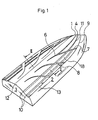
- the frame of the boat presented in Fig. 1 includes a keel 1, a side 2, a stern 3 and a base surface 4 of the bottom.
- Steps 5 according to the invention have been formed on the base surface 4.
- the steps rise from the base surface.
- the step is formed of a vertical end 6 increasing evenly in hight towards the bow, an end 7 near the edge of the side of the bottom and an edge 8 increasing evenly in hight from the keel towards the side of the bottom between the ends 6 and 7 as well as of a step surface 18 limited by the edges 6, 7, 8.
- On the surface of the step 5 two rising laths 10 parallel to each other and the seam line 9 have been attached.
- the rising laths start from the rare edge of the step i.e.
- the front part of the rising laths is at a distance appart from the previous edge 8.
- the front parts of the lateral rising laths 11 curve in a direction parallel to the seam line 9 and end at a distance appart from the keel 1.
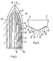
- Fig. 2 shows a view of the bottom structure according to Fig. 1 sectioned along the line II - II.
- the numbers are the same as in Fig. 1.
- the rising laths 10 have been formed on the bottom "in the wrong way" i.e. so that the surface 19 which faces the keel 1 is narrower than the surface 20 facing the side 2.
- Fig. 3 shows the directions of the flow of water at the bottom of a structure A which is in accordance with the invention as well as the flow of water at a normal V-shaped bottom structure B equiped with rising laths.
- the flow of water is as follows.
- the rising laths 11 farthest to the front direct the front splashes below the boat.
- the flow impacting on the first step 15 is effected by an underpressure which influences the flow and directs it along the edge of the step towards the keel.
- the boat Due to the flow pattern presented above the boat bears loads well, because the water is compacted below the bottom and won't splash away everywhere from below the bottom. Thus, the water resistance decreases and the boat moves easier. If the step srufaces 18 are divergent, the angle of impact is smallest at the first step 15 and largest at the last step 17.
- the presented bottom structure controls the planing of the boat so that the most advantageous driving position is achieved. As the load is incereased the angle of impact tends to increase, which gives rise to a counterforce which lifts the boat upwards. Because of this the boat is almost insensitive to changes in loading. According to the same principle the bottom functions also in rough waves and smoothens the passage of the boat.
Landscapes
- Physics & Mathematics (AREA)
- Fluid Mechanics (AREA)
- Chemical & Material Sciences (AREA)
- Engineering & Computer Science (AREA)
- Combustion & Propulsion (AREA)
- Mechanical Engineering (AREA)
- Ocean & Marine Engineering (AREA)
- Other Liquid Machine Or Engine Such As Wave Power Use (AREA)
- Toys (AREA)
- Hydraulic Turbines (AREA)
- Containers Having Bodies Formed In One Piece (AREA)
- Medicines Containing Plant Substances (AREA)
- Bathtubs, Showers, And Their Attachments (AREA)
Applications Claiming Priority (2)
| Application Number | Priority Date | Filing Date | Title |
|---|---|---|---|
| FI844937 | 1984-12-13 | ||
| FI844937A FI75126C (fi) | 1984-12-13 | 1984-12-13 | Baotens bottenkonstruktion. |
Publications (3)
| Publication Number | Publication Date |
|---|---|
| EP0184858A2 EP0184858A2 (en) | 1986-06-18 |
| EP0184858A3 EP0184858A3 (en) | 1987-01-21 |
| EP0184858B1 true EP0184858B1 (en) | 1990-06-06 |
Family
ID=8520053
Family Applications (1)
| Application Number | Title | Priority Date | Filing Date |
|---|---|---|---|
| EP85115936A Expired - Lifetime EP0184858B1 (en) | 1984-12-13 | 1985-12-13 | Bottom structure of a boat |
Country Status (9)
| Country | Link |
|---|---|
| US (1) | US4702188A (da) |
| EP (1) | EP0184858B1 (da) |
| JP (1) | JPS61184193A (da) |
| AU (1) | AU583330B2 (da) |
| CA (1) | CA1234727A (da) |
| DE (1) | DE3578058D1 (da) |
| DK (1) | DK162487C (da) |
| FI (1) | FI75126C (da) |
| NO (1) | NO170842C (da) |
Families Citing this family (17)
| Publication number | Priority date | Publication date | Assignee | Title |
|---|---|---|---|---|
| FI75126C (fi) * | 1984-12-13 | 1988-05-09 | Eero Harilainen | Baotens bottenkonstruktion. |
| USD299638S (en) | 1986-07-03 | 1989-01-31 | Ard Ernest E | Boat hull |
| WO1988006115A1 (en) * | 1987-02-12 | 1988-08-25 | Carib Dory (Aust.) Pty Limited | Multi-convertible boat hull |
| US5016552A (en) * | 1988-02-05 | 1991-05-21 | Ludlow Roy S | Boat hull |
| US5456202A (en) * | 1990-10-12 | 1995-10-10 | Schoell; Harry L. | Planing boat hull |
| US5404830A (en) * | 1992-05-11 | 1995-04-11 | Ligozio; Peter A. | Finned boat hull |
| JP2883548B2 (ja) * | 1994-10-03 | 1999-04-19 | 川崎重工業株式会社 | 滑走艇の船形 |
| US5819677A (en) * | 1996-07-17 | 1998-10-13 | Livingston; David T. | Hull with laminar flow interrupters |
| SE9700691L (sv) * | 1997-02-26 | 1998-08-27 | Volvo Penta Ab | Båtskrov |
| JP3111184B2 (ja) * | 1999-03-23 | 2000-11-20 | 川崎重工業株式会社 | 滑走艇の船底構造 |
| US20060254486A1 (en) * | 2005-05-12 | 2006-11-16 | Ashdown Glynn R | Winged hull for a watercraft |
| US7677192B2 (en) * | 2006-04-20 | 2010-03-16 | Randy Scism | Slot-V hull system |
| US20110297069A1 (en) * | 2010-06-07 | 2011-12-08 | Quimby John I | Boat hull strake design |
| US8613330B2 (en) | 2011-07-05 | 2013-12-24 | Schlumberger Technology Corporation | Coring tools and related methods |
| USD754562S1 (en) * | 2014-03-31 | 2016-04-26 | Patricia F. Harvey | Sand and water sleigh |
| WO2016073874A1 (en) | 2014-11-07 | 2016-05-12 | Ocean Design Group, Llc | Marine vessel hull with a longitudinally vented transverse step |
| US11319025B2 (en) | 2019-04-18 | 2022-05-03 | Cross Step Llc | Marine vessel hull with a longitudinally-vented, partial-beam transverse step |
Family Cites Families (13)
| Publication number | Priority date | Publication date | Assignee | Title |
|---|---|---|---|---|
| US1024682A (en) * | 1909-09-13 | 1912-04-30 | William Henry Fauber | Construction of boats and ships. |
| US2039586A (en) * | 1935-05-23 | 1936-05-05 | Eddy | Planing boat |
| US2162705A (en) * | 1938-01-22 | 1939-06-20 | Walter S Diehl | Hull spray reducing construction |
| US2919669A (en) * | 1957-07-19 | 1960-01-05 | Shin Meiwa Kogyo Kabushiki Kai | Spray-controller for watercraft |
| GB922199A (en) * | 1961-01-10 | 1963-03-27 | George Glen Eddy | Hull form |
| US3216389A (en) * | 1964-01-20 | 1965-11-09 | Ole I Thorsen | Boat hull |
| US3331347A (en) * | 1964-06-23 | 1967-07-18 | Heidenstam Erik Johan Von | Boats comprising means for introducing air to submerged portions of the boat bottom |
| US3450085A (en) * | 1967-05-10 | 1969-06-17 | Stanray Corp | Hydroplane boat hull |
| IT983574B (it) * | 1973-03-16 | 1974-11-11 | Molinari E | Carena di imbarcazione |
| SE7413890L (sv) * | 1974-11-06 | 1976-05-07 | Bo Oldenburg | Bottenkonstruktion for planande batar |
| GB1483133A (en) * | 1974-01-23 | 1977-08-17 | Oldenburg B | Boat hull |
| IT1129993B (it) * | 1980-02-04 | 1986-06-11 | Riccardo Mambretti | Carena a 'v' per motoscafi veloci con perfezioanti pattini di sostentamento idrodinamico |
| FI75126C (fi) * | 1984-12-13 | 1988-05-09 | Eero Harilainen | Baotens bottenkonstruktion. |
-
1984
- 1984-12-13 FI FI844937A patent/FI75126C/fi not_active IP Right Cessation
-
1985
- 1985-12-04 US US06/804,686 patent/US4702188A/en not_active Expired - Fee Related
- 1985-12-09 CA CA000497128A patent/CA1234727A/en not_active Expired
- 1985-12-12 DK DK575685A patent/DK162487C/da active
- 1985-12-12 NO NO855011A patent/NO170842C/no unknown
- 1985-12-12 AU AU51167/85A patent/AU583330B2/en not_active Ceased
- 1985-12-13 DE DE8585115936T patent/DE3578058D1/de not_active Expired - Lifetime
- 1985-12-13 EP EP85115936A patent/EP0184858B1/en not_active Expired - Lifetime
- 1985-12-13 JP JP60279339A patent/JPS61184193A/ja active Pending
Also Published As
| Publication number | Publication date |
|---|---|
| FI844937L (fi) | 1986-06-14 |
| FI75126C (fi) | 1988-05-09 |
| FI75126B (fi) | 1988-01-29 |
| EP0184858A2 (en) | 1986-06-18 |
| NO170842C (no) | 1992-12-16 |
| NO855011L (no) | 1986-06-16 |
| DE3578058D1 (de) | 1990-07-12 |
| DK575685A (da) | 1986-06-14 |
| NO170842B (no) | 1992-09-07 |
| DK162487B (da) | 1991-11-04 |
| EP0184858A3 (en) | 1987-01-21 |
| AU583330B2 (en) | 1989-04-27 |
| FI844937A0 (fi) | 1984-12-13 |
| CA1234727A (en) | 1988-04-05 |
| JPS61184193A (ja) | 1986-08-16 |
| DK575685D0 (da) | 1985-12-12 |
| DK162487C (da) | 1992-03-30 |
| US4702188A (en) | 1987-10-27 |
| AU5116785A (en) | 1986-06-19 |
Similar Documents
| Publication | Publication Date | Title |
|---|---|---|
| EP0184858B1 (en) | Bottom structure of a boat | |
| USRE36879E (en) | Planing boat hull | |
| US3930455A (en) | Boat hull construction | |
| US5063868A (en) | Boat hull for V-bottom powerboats | |
| US3342154A (en) | Boats | |
| US4708085A (en) | Marine hull | |
| RU1816272C (ru) | Корпус судна ледового плавани | |
| US3625173A (en) | Hulls for power boats | |
| CN101284564A (zh) | 船舶 | |
| US5231949A (en) | Dihedral tunnel boat hull | |
| US6176196B1 (en) | Boat bottom hull design | |
| US6016762A (en) | Planing foil for twin hulled boats | |
| US5588388A (en) | Hull shape of small watercraft | |
| US4958585A (en) | Boat hull | |
| AU2022203357B2 (en) | Inflatable motor boat | |
| US4932347A (en) | Jet ski hull | |
| US6237522B1 (en) | Bottom structure of personal watercraft | |
| US4002131A (en) | Boat hull construction | |
| JP3170255B2 (ja) | 滑走艇の船形 | |
| US7240632B1 (en) | Personal watercraft center keel | |
| JPS62116385A (ja) | 高速船 | |
| JP2015520063A (ja) | 荒海用の滑走型船体 | |
| US2249958A (en) | Boat hull | |
| US5819677A (en) | Hull with laminar flow interrupters | |
| US4528931A (en) | Stepped flotation apparatus |
Legal Events
| Date | Code | Title | Description |
|---|---|---|---|
| PUAI | Public reference made under article 153(3) epc to a published international application that has entered the european phase |
Free format text: ORIGINAL CODE: 0009012 |
|
| AK | Designated contracting states |
Kind code of ref document: A2 Designated state(s): BE DE FR GB IT NL SE |
|
| PUAL | Search report despatched |
Free format text: ORIGINAL CODE: 0009013 |
|
| AK | Designated contracting states |
Kind code of ref document: A3 Designated state(s): BE DE FR GB IT NL SE |
|
| 17P | Request for examination filed |
Effective date: 19870721 |
|
| 17Q | First examination report despatched |
Effective date: 19880224 |
|
| GRAA | (expected) grant |
Free format text: ORIGINAL CODE: 0009210 |
|
| AK | Designated contracting states |
Kind code of ref document: B1 Designated state(s): BE DE FR GB IT NL SE |
|
| PG25 | Lapsed in a contracting state [announced via postgrant information from national office to epo] |
Ref country code: NL Effective date: 19900606 Ref country code: BE Effective date: 19900606 |
|
| REF | Corresponds to: |
Ref document number: 3578058 Country of ref document: DE Date of ref document: 19900712 |
|
| ITF | It: translation for a ep patent filed | ||
| ET | Fr: translation filed | ||
| NLV1 | Nl: lapsed or annulled due to failure to fulfill the requirements of art. 29p and 29m of the patents act | ||
| ITTA | It: last paid annual fee | ||
| PLBE | No opposition filed within time limit |
Free format text: ORIGINAL CODE: 0009261 |
|
| STAA | Information on the status of an ep patent application or granted ep patent |
Free format text: STATUS: NO OPPOSITION FILED WITHIN TIME LIMIT |
|
| 26N | No opposition filed | ||
| REG | Reference to a national code |
Ref country code: GB Ref legal event code: 732 |
|
| REG | Reference to a national code |
Ref country code: FR Ref legal event code: TP |
|
| PGFP | Annual fee paid to national office [announced via postgrant information from national office to epo] |
Ref country code: GB Payment date: 19921202 Year of fee payment: 8 |
|
| PG25 | Lapsed in a contracting state [announced via postgrant information from national office to epo] |
Ref country code: GB Effective date: 19931213 |
|
| PGFP | Annual fee paid to national office [announced via postgrant information from national office to epo] |
Ref country code: SE Payment date: 19940620 Year of fee payment: 9 |
|
| PGFP | Annual fee paid to national office [announced via postgrant information from national office to epo] |
Ref country code: FR Payment date: 19940624 Year of fee payment: 9 |
|
| PGFP | Annual fee paid to national office [announced via postgrant information from national office to epo] |
Ref country code: DE Payment date: 19940630 Year of fee payment: 9 |
|
| GBPC | Gb: european patent ceased through non-payment of renewal fee |
Effective date: 19931213 |
|
| PG25 | Lapsed in a contracting state [announced via postgrant information from national office to epo] |
Ref country code: SE Effective date: 19941214 |
|
| EAL | Se: european patent in force in sweden |
Ref document number: 85115936.8 |
|
| PG25 | Lapsed in a contracting state [announced via postgrant information from national office to epo] |
Ref country code: FR Effective date: 19950831 |
|
| PG25 | Lapsed in a contracting state [announced via postgrant information from national office to epo] |
Ref country code: DE Effective date: 19950901 |
|
| EUG | Se: european patent has lapsed |
Ref document number: 85115936.8 |
|
| REG | Reference to a national code |
Ref country code: FR Ref legal event code: ST |