EP0184862A2 - Avertisseur de décrochage pour avion - Google Patents
Avertisseur de décrochage pour avion Download PDFInfo
- Publication number
- EP0184862A2 EP0184862A2 EP85201147A EP85201147A EP0184862A2 EP 0184862 A2 EP0184862 A2 EP 0184862A2 EP 85201147 A EP85201147 A EP 85201147A EP 85201147 A EP85201147 A EP 85201147A EP 0184862 A2 EP0184862 A2 EP 0184862A2
- Authority
- EP
- European Patent Office
- Prior art keywords
- signal
- aircraft
- producing
- thrust
- representative
- Prior art date
- Legal status (The legal status is an assumption and is not a legal conclusion. Google has not performed a legal analysis and makes no representation as to the accuracy of the status listed.)
- Granted
Links
Images

Classifications
-
- G—PHYSICS
- G05—CONTROLLING; REGULATING
- G05D—SYSTEMS FOR CONTROLLING OR REGULATING NON-ELECTRIC VARIABLES
- G05D1/00—Control of position, course, altitude or attitude of land, water, air or space vehicles, e.g. using automatic pilots
- G05D1/04—Control of altitude or depth
- G05D1/06—Rate of change of altitude or depth
- G05D1/0607—Rate of change of altitude or depth specially adapted for aircraft
-
- B—PERFORMING OPERATIONS; TRANSPORTING
- B64—AIRCRAFT; AVIATION; COSMONAUTICS
- B64D—EQUIPMENT FOR FITTING IN OR TO AIRCRAFT; FLIGHT SUITS; PARACHUTES; ARRANGEMENT OR MOUNTING OF POWER PLANTS OR PROPULSION TRANSMISSIONS IN AIRCRAFT
- B64D43/00—Arrangements or adaptations of instruments
- B64D43/02—Arrangements or adaptations of instruments for indicating aircraft speed or stalling conditions
Definitions
- the present invention pertains to the aircraft control art and, more particularly, to an improved system for producing an aircraft stall warning signal.
- the low speed aerodynamic performance of aircraft is typically based upon stall speeds determined from stall tests which are conducted with the aircraft's engines set at idle power.
- the idle power test is done because this condition provides the highest, and thus most conservative, stall speed.
- the idle power stall speeds are then used as the basis for setting the normal operational speeds of the aircraft at all power settings.
- the minimum usable speed within the normal flight envelope of the aircraft is the stall warning speed. By regulation, the minimum flight envelope speed for an aircraft must be at least 796 above the demonstrated stall speed.
- the pilot of the aircraft is typically warned that the craft is approaching a stall condition by "stick shaker" action on his column.
- the stick shaker condition is triggered by the angle of attack of the aircraft, as determined by an angle of attack vane, approaching the stall warning speed level.
- the pilot is trained to react to the stall warning by pushing forward on the control column to regain speed and thus avoid inadvertent aircraft stall.
- FIG. 1 is a graph illustrating the relationship of aircraft lift coefficient C L to the aircraft angle of attack, ⁇ .
- Graph 12 plots the lift coefficient C L with the engine set.at idle thrust. The stall condition is indicated at the peak of graph 12. To prevent the aircraft from actually flying to a stall condition, the stall warning, a stall warning, is established at a lower angle of attack, as indicated.
- Graph 14 illustrates the aircraft's coefficient of lift under maximum engine thrust. If the same stall warning angle of attack is used under maximum thrust conditions, it is apparent that the stall warning will be given at warning speeds which are lower than the idle power demonstrated stall speed. As such, undesirable excursions outside of the aircraft's usable speed envelope are possible since no advance warning is provided.
- the present invention is directed to an improved stall warning system which provides a correction signal, Aa, to modify the stall warning signal as a function of engine thrust such that an advance warning signal is produced which provides a stall warning that is essentially invariant with engine power.
- apparatus for producing an aircraft stall warning signal comprises a means for producing a signal a which is representative of the aircraft angle of attack.
- a correction signal, Aa which is predeterminedly related to engine thrust level is produced by Aa means.
- a comparator compares the a and Aa signals and produces a stall warning signal in response to a predetermined relationship therebetween.
- the Aa means includes means for producing a signal CT C which is representative of aircraft gross thrust coefficient.
- the ⁇ signal is scheduled as a predetermined function of the C TG gross thrust coefficient signal.
- FIG. 1 is a graph illustrating aircraft stall speed profiles. Plotted is aircraft lift coefficient, C L , versus aircraft angle of attack, a . Two graphs appear in this figure. Graph 12 is the lift profile for an aircraft at idle thrust. Identified at the peak of this graph is the aircraft's lift coefficient at stall. To assure a stall warning in advance of this stall condition, the minimum usable aircraft speed has been set at an advance angle of attack, indicated in FIG. 1 as ⁇ stall warning.
- the inadequacy of the conventional advance lift warning is illustrated by the graph 14 which plots the aircraft lift profile at maximum engine thrust.
- the additional lift provided by the component of thrust acting in the lift direction significantly reduces aircraft stall speed.
- this effect is particularly pronounced.
- the full power stall speed as illustrated in FIG. 1 can be 10-15 knots lower than the idle power demonstrated stall speed.
- the stall warning speed is lower than the idle power demonstrated stall speed.
- the pilot does not, therefore, receive a stall warning until his speed is actually lower than the demonstrated stall speed. Consequently, excursions outside the usable aircraft speed envelope are possible. This could prove critical since the handling characteristics of the aircraft may seriously deteriorate below the envelope usable speed level.
- the present improved stall warning system develops a correction signal which is based on engine power setting.
- the present invention incorporates a stall warning schedule which automatically provides an advanced stall warning with increasing engine power.
- the present improved stall warning system provides advanced stall warnings to prevent speed excursions outside of the usable aircraft speed envelope at all engine power settings.
- the preferred embodiment of the invention is directed to a stall warning system which employs a control column "stick shaker" which is triggered by an angle of attack vane signal to alert the pilot of a near stall condition.
- a device in accordance with the present invention automatically adjusts the vane angle trigger point to a lower setting with increasing engine thrust coefficient.
- FIG. 2 is a graph of aircraft vane angle of attack a vs. the total aircraft gross thrust coefficient, C TG .
- Aircraft gross thrust coefficient is defined as:
- Graph 20 in FIG. 2 sets forth the preferred schedule of vane angle vs. thrust coefficient used to implement the present invention.
- the vane angle a for relatively low thrust coefficients is identified as a max and corresponds to the standard idle thrust stall warning vane angle.
- the stall warning bias remains constant at a minimum value, ⁇ min .
- the maximum correction signal, Aa which need be applied to the idle thrust stall warning vane angle signal ⁇ max is the ⁇ max signal as illustrated.
- the present invention develops the Aa signal to correct the a max idle thrust stall warning signal to the schedule as shown in FIG. 2.
- the active bias schedule 22 Extending between the maximum and minimum stall warning levels ⁇ max , ⁇ min, respectively, is the active bias schedule 22. As shown, in the preferred embodiment of the invention the active region 22 is linear. The active region 22 of the Aa schedule selected for a particular aircraft depends upon several variables. First, the schedule 22 should be selected to provide good aircraft handling capabilities into stall at all thrust settings. Also, the schedule 22 should be selected in accordance with prudent design for aircraft handling during windshear conditions. In addition, the schedule 22 should minimize nuisance trips, i.e., stick shaker indications which do not represent a near stall condition.
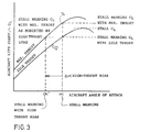
- FIG. 3 is a graph, similar to the graph of FIG. 1, but illustrating the revised stall warning level at high engine thrust due to implementation of the correction signal Aa.
- graph 12 illustrates the lift profile of an aircraft with its engines at an idle thrust setting. The stall condition is indicated at the peak of this graph.
- astall warning-Graph 14 depicts the aircraft stall profile at maximum engine thrust. If the stall warning level ⁇ stall warning is used for the maximum thrust condition of graph 14, it is seen that the stall warning speed is less than the demonstrated stall speed. As such, no advance warning is provided.
- stall warning signal ⁇ stall warning is corrected by the correction signal Aa in accordance with the schedule of FIG. 2, a new stall warning level is established, as indicated at ao stall warning with high thrust bias.
- the use of the Aa correction signal modifies the vane angle warning signal a stall warning such that the stick shaker stall warning level is essentially invariant with engine power, and thus provides advance stall warning at all power settings.
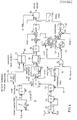
- FIG. 4 is a detailed block diagram setting forth the preferred apparatus for realizing the improved aircraft stall warning system.
- the angle of attack correction signal ⁇ is scheduled as a function of aircraft gross thrust coefficient, C TG , where:
- the circuitry indicated generally at 30 develops the C TG signal.
- %N I Applied to the input of a block 32 is a signal %N I , which is a commonly available signal in a turbine engine aircraft and corresponds to the percentage of maximum thrust being produced by the engine. Over a defined active range (65%-91% max thrust for the engine of the preferred embodiment) the gross thrust developed by the engine is directly proportional to the %N signal. Thus, the output from the gross thrust block 32 is a signal T G which represents the gross thrust being produced by the aircraft's first engine.
- the signal T G is passed to the numerator input of a divider block 34.
- a signal s which corresponds to the aircraft's wing area.
- the signal out of divider block 34 has the form T G/s . This signal is applied as the numerator input to a divider block 36.
- SELECT HIGH Applied to the inputs of a "SELECT HIGH" block 40 are a reference signal V REF and a calibrated airspeed signal V CAS .
- the signal V CAS corresponds to the aircraft's actual calibrated airspeed.
- the signal V REF is selected to prevent a subsequent divide by 0, and also to allow a desired maximum advance level.
- the larger of the signals applied to the input of SELECT HIGH block 40 is passed to a squarer circuit 42.
- the output from squarer circuit 42 is, thus, a signal having a level V 2 .
- the signal V 2 out of squarer block 42 is passed to the numerator input of a divider block 44.
- Applied to the denominator input of divider block 44 is a constant, k, which converts calibrated airspeed squared to dynamic pressure.
- the signal out of divider block 44 is representative of dynamic pressure, and given the symbol q.
- the signal developed at the output of divider block 36 is, therefore, the aircraft's gross thrust coefficient C TG .
- the gross thrust coefficient C TG is passed as one input to a high thrust bias schedule block 50. Also applied as an input to high thrust bias schedule block 50 is a signal representative of aircraft flap position. High thrust bias schedule 50 operates in accordance with the graph of FIG. 2 to produce an output correction signal ⁇ which is used to correct the stall warning signal for engine thrust. Since this schedule, in the preferred embodiment, may also vary as a function of flap position, two different curves for two different flap positions are developed.
- the ⁇ correction signal out of high thrust bias schedule block 50 is passed to the "false” input of a switch 60. Passed to the "true” input of switch 60 is a signal representative of a Aa of 0 0. Applied to the control input of switch 60 is the output from circuitry, collectively indicated at 70, which determines whether or not both engines on the aircraft are developing minimum thrust levels.
- the circuitry 70 includes a comparator block 72 which receives the N 2 signal as developed from the second of the two aircraft's engines. The output from the comparator block 72 is a logic level related to whether or not the second engine is developing less than a reference N 2 of 75%. A similar signal "N 1 VALID" is developed for the aircraft's first engine.
- the output from switch 60 is applied to one input of a "SELECT HIGH" block 80. Applied to the remaining input of SELECT HIGH block 80 is a developed worst case warning signal ⁇ WC. If the aircraft is operating with an asymmetrical flap deployment, a stall condition can occur at a lower aircraft angle of attack.
- the signal a wc is selected such that in the event of an asymmetrical flap deployment, a stall warning will be given in advance of a stall condition.
- the ⁇ WC signal is developed from a flap position schedule block 90 and a switch block 92.
- the flap position block 90 receives a signal corresponding to flap position at an input and produces an output signal which is a scheduled worst case a wc as a function of flap position. This signal is passed to the "true" input of switch 92, which receives a representative 0 o signal level at its "false” input. If circuitry (not shown) determines that there is an asymmetrical flap deployment, switch 92 is activated to its "true” position, thereby passing the a wc signal to the "SELECT HIGH" block 80. Otherwise, the 0 level signal is passed to SELECT HIGH block 80.
- the SELECT HIGH block 80 passes the higher of the two signals at its inputs to the negative input of a summer 110. Assuming that the aircraft is not in a condition of flap asymmetry, and that both engines are producing the required minimum thrust level, the signal applied to the negative input of summer 110 will be the ⁇ signal out of the high thrust bias schedule block 50.
- Normal trip schedule block 120 receives as an input flap position and operates to produce a conventional stall warning limit signal, ⁇ LIMIT, as a function of flap position.
- the signal out of the summer circuit 110 is the difference between the standard ⁇ LIMIT signal and the correction signal ⁇ .
- This signal Is then subtracted, in a summer circuit 130, from a signal ⁇ VANE which is the signal produced by the aircraft's angle of attack vane. If the aircraft's actual angle of attack exceeds the stall warning reference signal which is equal to the standard limit signal ⁇ LIMIT minus the correction signal ⁇ , this indicates that the aircraft is in a near stall condition and a stick shaker alert should be given.
- the stick shaker alert is developed by means of a "GREATER THAN 0" circuit 140 which produces an output logic level in response to the angle of attack signal ⁇ VANE exceeding the difference between the ⁇ LIMIT signal and the correction signal ⁇ .
- the output from the GREATER THAN 0 block 140 is applied at one input to a logic OR gate 150. Applied to the remaining input to OR gate 150 is the output from a "GREATER THAN 0" block 160.
- circuitry indicated generally at 170, produces a stick shaker signal in the event that the aircraft's calibrated airspeed falls below a scheduled level.
- a "MINIMUM CALIBRATED AIRSPEED" block 172 receives an input signal representative of flap position.
- a schedule within the MINIMUM CALIBRATED AIRSPEED block 172 produces an output signal corresponding to the minimum airspeed allowed at that flap position.
- Subtracted from the minimum airspeed signal, in a summer 174 is a signal representative of the aircraft's actual calibrated airspeed. If the output from the summer 174 is greater than 0, indicating that the aircraft is flying below the scheduled airspeed, the GREATER THAN 0 block 160 produces a logical input to the OR gate 150.
- the OR gate 150 receives an output from either the GREATER THAN 0 block 140 or the GREATER THAN 0 block 160, it produces an output to the "false" input of a switch 180.
- switch 180 Applied to the "true" input of switch 180 is a reference 0 level signal. If suitable circuitry (not shown) such as a "squat" switch indicates that the aircraft is on the ground, switch 180 is activated to its true position, whereby a 0 level signal is passed to the output. However, once the aircraft is airborne, switch 180 passes the signal out of OR gate 150, thereby allowing a stall warning signal to be passed to the standard "stick shaker" circuitry, not shown. This, then, alerts the pilot of a near stall condition.
- suitable circuitry such as a "squat" switch indicates that the aircraft is on the ground
- switch 180 is activated to its true position, whereby a 0 level signal is passed to the output. However, once the aircraft is airborne, switch 180 passes the signal out of OR gate 150, thereby allowing a stall warning signal to be passed to the standard "stick shaker" circuitry, not shown. This, then, alerts the pilot of a near stall condition.
- the described stall warning system takes into account engine thrust level to produce a stall warning advance which is essentially invariant with thrust level. In this way, the aircraft is maintained within its minimum speed envelope over all engine power settings.
Landscapes
- Engineering & Computer Science (AREA)
- Aviation & Aerospace Engineering (AREA)
- Radar, Positioning & Navigation (AREA)
- Remote Sensing (AREA)
- Physics & Mathematics (AREA)
- General Physics & Mathematics (AREA)
- Automation & Control Theory (AREA)
- Emergency Alarm Devices (AREA)
- Alarm Systems (AREA)
Applications Claiming Priority (2)
| Application Number | Priority Date | Filing Date | Title |
|---|---|---|---|
| US06/671,134 US4908619A (en) | 1984-11-13 | 1984-11-13 | Aircraft stall warning system |
| US671134 | 1996-06-27 |
Publications (3)
| Publication Number | Publication Date |
|---|---|
| EP0184862A2 true EP0184862A2 (fr) | 1986-06-18 |
| EP0184862A3 EP0184862A3 (en) | 1987-11-11 |
| EP0184862B1 EP0184862B1 (fr) | 1991-01-16 |
Family
ID=24693263
Family Applications (1)
| Application Number | Title | Priority Date | Filing Date |
|---|---|---|---|
| EP85201147A Expired - Lifetime EP0184862B1 (fr) | 1984-11-13 | 1985-07-09 | Avertisseur de décrochage pour avion |
Country Status (3)
| Country | Link |
|---|---|
| US (1) | US4908619A (fr) |
| EP (1) | EP0184862B1 (fr) |
| DE (1) | DE3581381D1 (fr) |
Cited By (5)
| Publication number | Priority date | Publication date | Assignee | Title |
|---|---|---|---|---|
| EP0377231A3 (fr) * | 1989-01-06 | 1990-08-08 | The Boeing Company | Méthode et dispositif pour réduire les alertes fautives des sauts de vent |
| EP0586529A4 (fr) * | 1991-05-09 | 1995-04-19 | Sundstrand Corp | Systeme independant d'avertissement de faible vitesse vraie. |
| EP0743242A1 (fr) * | 1995-05-15 | 1996-11-20 | The Boeing Company | Système de protection contre le décrochage pour autopilote/directeur de vol |
| DE19600335A1 (de) * | 1996-01-08 | 1997-07-10 | Bundesrep Deutschland | Verfahren und Anordnung zur Warnung vor dem Überziehen eines Flugzeuges |
| EP0743241B2 (fr) † | 1995-05-15 | 2009-04-22 | The Boeing Company | Système de protection contre la sous-vitesse pour autopilote/directeur de vol |
Families Citing this family (15)
| Publication number | Priority date | Publication date | Assignee | Title |
|---|---|---|---|---|
| FR2643502B1 (fr) * | 1989-02-20 | 1996-01-19 | Aerospatiale | Dispositif de commande a manche basculant, notamment pour aeronef, et systeme comportant un tel dispositif |
| US5057832A (en) * | 1991-04-09 | 1991-10-15 | England Samuel G | Audible glide speed indicator apparatus |
| US5590853A (en) * | 1992-02-03 | 1997-01-07 | Safe Flight Instrument Corporation | Aircraft control system |
| DE19538894A1 (de) * | 1995-10-19 | 1997-04-24 | Philips Patentverwaltung | Navigationssystem für ein Fahrzeug |
| US6131055A (en) * | 1998-12-11 | 2000-10-10 | The Boeing Company | Aircraft non-normalized angle-of-attack indicating system |
| US6246929B1 (en) | 1999-06-16 | 2001-06-12 | Lockheed Martin Corporation | Enhanced stall and recovery control system |
| US6236914B1 (en) | 1999-06-16 | 2001-05-22 | Lockheed Martin Corporation | Stall and recovery control system |
| FR2869588B1 (fr) * | 2004-04-28 | 2006-07-14 | Airbus France Sas | Procede d'aide au decollage d'un aeronef. |
| US7395705B2 (en) * | 2006-06-21 | 2008-07-08 | Greene Leonard M | System for measuring an airflow angle at the wingtip of an aircraft |
| US8508387B2 (en) * | 2007-05-24 | 2013-08-13 | Aviation Communication & Surveillance Systems Llc | Systems and methods for aircraft windshear detection |
| US7902999B2 (en) * | 2008-04-18 | 2011-03-08 | Honeywell International Inc. | Gas turbine engine rotor lock prevention system and method |
| US8653990B2 (en) * | 2012-06-18 | 2014-02-18 | The Boeing Company | Stall management system |
| US9440747B1 (en) | 2015-05-06 | 2016-09-13 | Aviation Safety Advancements, Inc. | Aircraft recovery control |
| US9969503B2 (en) * | 2016-07-21 | 2018-05-15 | Rockwell Collins, Inc. | Head-up display (HUD) stall recovery symbology |
| US12037008B2 (en) | 2022-04-07 | 2024-07-16 | Toyota Research Institute, Inc. | Systems and methods for communicating a blending parameter |
Family Cites Families (13)
| Publication number | Priority date | Publication date | Assignee | Title |
|---|---|---|---|---|
| US2933268A (en) * | 1956-11-13 | 1960-04-19 | Sperry Rand Corp | Automatic flight control system for aircraft |
| US3522729A (en) * | 1968-01-22 | 1970-08-04 | Sperry Rand Corp | Airspeed command system |
| US3839699A (en) * | 1969-08-05 | 1974-10-01 | Monitair Corp | Aircraft stall warning indicator system based on rate of change of angle of attack |
| US3686936A (en) * | 1970-02-11 | 1972-08-29 | Charles H Daudt Jr | Method and apparatus for detecting stall buffet |
| GB1476402A (en) * | 1975-05-23 | 1977-06-16 | Maris J | Warning devices |
| US4019702A (en) * | 1975-11-13 | 1977-04-26 | The Boeing Company | Method and apparatus for guiding a jet aircraft in a noise-abated post-takeoff climb |
| GB1563501A (en) * | 1976-02-11 | 1980-03-26 | Elliott Bros | Aircrft instruments |
| US4027839A (en) * | 1976-03-30 | 1977-06-07 | General Electric Company | High angle of attack aircraft control system utilizing a pseudo acceleration signal for control purposes |
| US4230290A (en) * | 1978-05-01 | 1980-10-28 | Townsend Engineering Company | Airplane angle of attack and direction of flight indicator |
| US4235104A (en) * | 1979-03-19 | 1980-11-25 | The Board Of Trustees Of Western Michigan University | Normalized coefficient of lift indicator |
| US4347572A (en) * | 1979-11-02 | 1982-08-31 | The Boeing Company | Method and apparatus for an aircraft climb-out guidance system |
| US4326253A (en) * | 1980-03-31 | 1982-04-20 | The Boeing Company | Lift control system for aircraft vertical path guidance |
| US4467429A (en) * | 1982-01-13 | 1984-08-21 | The United States Of America As Represented By The Secretary Of The Air Force | Aircraft thrust control scheme for terrain following system |
-
1984
- 1984-11-13 US US06/671,134 patent/US4908619A/en not_active Expired - Lifetime
-
1985
- 1985-07-09 EP EP85201147A patent/EP0184862B1/fr not_active Expired - Lifetime
- 1985-07-09 DE DE8585201147T patent/DE3581381D1/de not_active Expired - Lifetime
Cited By (6)
| Publication number | Priority date | Publication date | Assignee | Title |
|---|---|---|---|---|
| EP0377231A3 (fr) * | 1989-01-06 | 1990-08-08 | The Boeing Company | Méthode et dispositif pour réduire les alertes fautives des sauts de vent |
| EP0586529A4 (fr) * | 1991-05-09 | 1995-04-19 | Sundstrand Corp | Systeme independant d'avertissement de faible vitesse vraie. |
| EP0743242A1 (fr) * | 1995-05-15 | 1996-11-20 | The Boeing Company | Système de protection contre le décrochage pour autopilote/directeur de vol |
| EP0743241B2 (fr) † | 1995-05-15 | 2009-04-22 | The Boeing Company | Système de protection contre la sous-vitesse pour autopilote/directeur de vol |
| DE19600335A1 (de) * | 1996-01-08 | 1997-07-10 | Bundesrep Deutschland | Verfahren und Anordnung zur Warnung vor dem Überziehen eines Flugzeuges |
| DE19600335C2 (de) * | 1996-01-08 | 1998-02-19 | Bundesrep Deutschland | Verfahren und Anordnung zur Warnung vor dem Überziehen eines Flugzeuges |
Also Published As
| Publication number | Publication date |
|---|---|
| EP0184862A3 (en) | 1987-11-11 |
| EP0184862B1 (fr) | 1991-01-16 |
| DE3581381D1 (de) | 1991-02-21 |
| US4908619A (en) | 1990-03-13 |
Similar Documents
| Publication | Publication Date | Title |
|---|---|---|
| EP0184862B1 (fr) | Avertisseur de décrochage pour avion | |
| US5225829A (en) | Independent low airspeed alert | |
| EP0028435B1 (fr) | Système de guidage d'avion en montée | |
| US4551723A (en) | Excessive descent rate warning system for rotary wing aircraft | |
| US5781126A (en) | Ground proximity warning system and methods for rotary wing aircraft | |
| EP0215115B1 (fr) | Systeme d'avertissement de proximite du sol pour aeronefs a avertissement modifie par la configuration et a commutation amelioree de mode | |
| US4951047A (en) | Negative climb after take-off warning system | |
| CA1177562A (fr) | Systeme d'avertissement de la proximite du sol avec commutation de mode fonction du temps | |
| US5136518A (en) | Pitch guidance system | |
| US4849756A (en) | Ground proximity warning system terrain classification system | |
| EP0037159A2 (fr) | Commande de sustentation pour avions | |
| WO1989006846A1 (fr) | Systeme d'avertissement et d'alerte de cisaillement du au vent sensible a la trajectoire de vol d'un aeronef | |
| US4993919A (en) | Discrete (on-off) feather signal to govern propeller overspeed | |
| US4818992A (en) | Excessive altitude loss after take-off warning system for rotary wing aircraft | |
| EP0217852B1 (fr) | Systeme d'avertissement d'approche du sol pour aeronefs a enveloppe modifiee sur la base de la vitesse descensionnelle | |
| CA1234417A (fr) | Systeme avertissant le pilote de profils de vol dangereux au cours d'evolutions a basse altitude | |
| US4916447A (en) | Warning system for aircraft landing with landing gear up | |
| US4530060A (en) | Aircraft speed control system modified for decreased headwind at touchdown | |
| GB2140368A (en) | Excessive terrain closure warning system | |
| WO1986001022A1 (fr) | Systeme d'avertissement de la proximite du sol pour avions a performances degradees | |
| CA1295716C (fr) | Dispositif avertisseur de proximite du sol pour les aeronefs ayant des performances degradees | |
| GB2140757A (en) | Excessive descent rate warning system for tactical aircraft |
Legal Events
| Date | Code | Title | Description |
|---|---|---|---|
| PUAI | Public reference made under article 153(3) epc to a published international application that has entered the european phase |
Free format text: ORIGINAL CODE: 0009012 |
|
| AK | Designated contracting states |
Kind code of ref document: A2 Designated state(s): DE FR GB IT NL |
|
| PUAL | Search report despatched |
Free format text: ORIGINAL CODE: 0009013 |
|
| AK | Designated contracting states |
Kind code of ref document: A3 Designated state(s): DE FR GB IT NL |
|
| 17P | Request for examination filed |
Effective date: 19871120 |
|
| 17Q | First examination report despatched |
Effective date: 19881216 |
|
| ITF | It: translation for a ep patent filed | ||
| GRAA | (expected) grant |
Free format text: ORIGINAL CODE: 0009210 |
|
| AK | Designated contracting states |
Kind code of ref document: B1 Designated state(s): DE FR GB IT NL |
|
| ET | Fr: translation filed | ||
| REF | Corresponds to: |
Ref document number: 3581381 Country of ref document: DE Date of ref document: 19910221 |
|
| PLBE | No opposition filed within time limit |
Free format text: ORIGINAL CODE: 0009261 |
|
| STAA | Information on the status of an ep patent application or granted ep patent |
Free format text: STATUS: NO OPPOSITION FILED WITHIN TIME LIMIT |
|
| 26N | No opposition filed | ||
| REG | Reference to a national code |
Ref country code: GB Ref legal event code: IF02 |
|
| REG | Reference to a national code |
Ref country code: FR Ref legal event code: D6 |
|
| PGFP | Annual fee paid to national office [announced via postgrant information from national office to epo] |
Ref country code: NL Payment date: 20040616 Year of fee payment: 20 |
|
| PGFP | Annual fee paid to national office [announced via postgrant information from national office to epo] |
Ref country code: GB Payment date: 20040630 Year of fee payment: 20 |
|
| PGFP | Annual fee paid to national office [announced via postgrant information from national office to epo] |
Ref country code: FR Payment date: 20040720 Year of fee payment: 20 |
|
| PGFP | Annual fee paid to national office [announced via postgrant information from national office to epo] |
Ref country code: DE Payment date: 20040831 Year of fee payment: 20 |
|
| PG25 | Lapsed in a contracting state [announced via postgrant information from national office to epo] |
Ref country code: GB Free format text: LAPSE BECAUSE OF EXPIRATION OF PROTECTION Effective date: 20050708 |
|
| PG25 | Lapsed in a contracting state [announced via postgrant information from national office to epo] |
Ref country code: NL Free format text: LAPSE BECAUSE OF EXPIRATION OF PROTECTION Effective date: 20050709 |
|
| REG | Reference to a national code |
Ref country code: GB Ref legal event code: PE20 |
|
| NLV7 | Nl: ceased due to reaching the maximum lifetime of a patent |
Effective date: 20050709 |