EP0184884B1 - Halter für einen Kabelüberschuss - Google Patents
Halter für einen Kabelüberschuss Download PDFInfo
- Publication number
- EP0184884B1 EP0184884B1 EP19850201971 EP85201971A EP0184884B1 EP 0184884 B1 EP0184884 B1 EP 0184884B1 EP 19850201971 EP19850201971 EP 19850201971 EP 85201971 A EP85201971 A EP 85201971A EP 0184884 B1 EP0184884 B1 EP 0184884B1
- Authority
- EP
- European Patent Office
- Prior art keywords
- shell
- cord
- slot
- cord holder
- holder according
- Prior art date
- Legal status (The legal status is an assumption and is not a legal conclusion. Google has not performed a legal analysis and makes no representation as to the accuracy of the status listed.)
- Expired
Links
- 239000011796 hollow space material Substances 0.000 claims 1
- 238000003780 insertion Methods 0.000 description 4
- 230000037431 insertion Effects 0.000 description 4
- 238000004519 manufacturing process Methods 0.000 description 2
- 239000002131 composite material Substances 0.000 description 1
- 239000004020 conductor Substances 0.000 description 1
- 238000000034 method Methods 0.000 description 1
- 230000035939 shock Effects 0.000 description 1
- 238000004904 shortening Methods 0.000 description 1
Images


Classifications
-
- H—ELECTRICITY
- H02—GENERATION; CONVERSION OR DISTRIBUTION OF ELECTRIC POWER
- H02G—INSTALLATION OF ELECTRIC CABLES OR LINES, OR OF COMBINED OPTICAL AND ELECTRIC CABLES OR LINES
- H02G11/00—Arrangements of electric cables or lines between relatively-movable parts
- H02G11/02—Arrangements of electric cables or lines between relatively-movable parts using take-up reel or drum
-
- B—PERFORMING OPERATIONS; TRANSPORTING
- B65—CONVEYING; PACKING; STORING; HANDLING THIN OR FILAMENTARY MATERIAL
- B65H—HANDLING THIN OR FILAMENTARY MATERIAL, e.g. SHEETS, WEBS, CABLES
- B65H75/00—Storing webs, tapes, or filamentary material, e.g. on reels
- B65H75/02—Cores, formers, supports, or holders for coiled, wound, or folded material, e.g. reels, spindles, bobbins, cop tubes, cans, mandrels or chucks
- B65H75/34—Cores, formers, supports, or holders for coiled, wound, or folded material, e.g. reels, spindles, bobbins, cop tubes, cans, mandrels or chucks specially adapted or mounted for storing and repeatedly paying-out and re-storing lengths of material provided for particular purposes, e.g. anchored hoses, power cables
- B65H75/36—Cores, formers, supports, or holders for coiled, wound, or folded material, e.g. reels, spindles, bobbins, cop tubes, cans, mandrels or chucks specially adapted or mounted for storing and repeatedly paying-out and re-storing lengths of material provided for particular purposes, e.g. anchored hoses, power cables without essentially involving the use of a core or former internal to a stored package of material, e.g. with stored material housed within casing or container, or intermittently engaging a plurality of supports as in sinuous or serpentine fashion
Definitions
- This invention generally relates to a surplus cord holder for storing a slack of a cord of the kind generally defined in the preamble of claim 1. More specifically the invention is directed to cords for electrical and electronic appliances, although the invention, of course, is not restricted hereto.
- Cords of lighting accessories and other electrical appliances have either a length which is initially dimensioned just for its intended use, or a length which is too great or too small. In those instances where the cord is too short an extension cord is often used which means that the total length of the composite cord becomes too great even in this instance. Apart from those cases where the cord is initially dimensioned just for its intended purpose, all cases do consequently have too long a cord.
- US-3 068 316 discloses a cord shortening holder comprising an elongated tubular shell.
- the shell ends are partially closed by radially inwardly directed, triangular, resilient teeth which define a star-like opening.
- the cord to be shortened is passed axially through the holder so that it projects from opposite ends.
- the end of the cord e.g. an electric plug
- the flexible teeth of the shell ends are deflected and subsequently grip the cord frictionally.
- the surplus length of the cord which it is desired to store in the holder, may be pushed into one or both ends of the holder whereupon it will fold or coil upon itself therein.
- the turns or coils of the stored portion of the cord extend in planes which are substantially traverse to the axial direction of the tubular cord holder.
- Another cord holder of the prior art disclosed in US-2 160 961 also comprises an elongated, tubular shell having semi-spherical ends provided with openings, the dimensions of which are adapted to the cross dimension of the cord.
- the shell is comprised of two halves which may be resilient, at least in part, and are hingedly connected to each other along a generatrix of the tubular shell. This enables the shell to be opened and the cord to be introduced into the shell.
- the shell halves are maintained in their closed position either by the resiliency of the shell or by latch means.
- the surplus length of the cord is folded upon itself in the shell in a serpentine-like manner, the straight portions of the cord extending in the longitudinal direction of the shell.
- the principal object of the invention is to provide an improved surplus cord holder for storing a slack portion of a cord which is intended particularly for electrical appliances, such as lamps, radio and TV apparatus, loudspeakers and stereo equipments, telephones and so on, and also can be used in other fields of the technique.
- a further object is to provide a cord holder which is simple in structure and presents a neat and ornamental appearance.
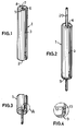
- the principal component of the surplus cord holder according to the invention is an elongated, tubular shell 1 which has an open end 2 and is provided with a slot 3 extending longitudinally from end to end of the shell 1.
- the slot 3 is sufficiently wide to permit the introduction of a standard, two-conductor plug-in cord for electrical lamps and the like.
- One end (the upper one in Figs. 1,2,7, 9 and 10) 4 of the shell is permanently closed by an end member 4 which is preferably integral with the shell 1.
- the end member has a slot which is generally designated 5 and constitutes a direct continuation of the slot 3 of the shell 1.
- the slot 5 comprises an enlargement 6 through which the cord can run freely, and a narrower inner end 7 which preferably is located centrally and so dimensioned that its edges frictionally engage the outer surface of said electrical standard cord.
- the end cap 9 has a substantially radial slot which corresponds to the slot 5 of the other end of the shell 1 and is generally designated 10.
- the slot 10 has a narrower end portion 11 which is preferably centrally located and which is so dimensioned that its edges frictionally engage the outer surface of the cord.
- the cap 9 is provided with a waist or annular recess 12 into which an internal, annular projection or upset 13 at the lower end 2 of the shell 1 is intended to snap in when the end cap 9 is joined to the shell.
- Figs. 8-10 illustrate the insertion of a cord 20 having a surplus length or slack into the cord holder according to the invention.
- a length of the cord 20 corresponding to the slack is folded several times upon itself into a skein 21 the turns of which are compressed (Fig. 8) and given a length which is a little shorter than that of the cord holder 1.
- the cord 20 is introduced into the longitudinal slot 3 and the radial slot 5 in which it is suitably positioned in the enlargement 6, as is shown in Fig. 9.
- the cord which is located immediately above the cord holder in Fig. 9, is pressed in into the shell 1 in the direction of the arrow B in Fig. 9. This operation may be carried out by pulling the skein 21 leftwards in Fig. 9.
- cord slack holder is not restricted to electrical cords but may be used also in connection with non-electric cords, such as cables, ropes and wires.
Landscapes
- Insertion, Bundling And Securing Of Wires For Electric Apparatuses (AREA)
- Storage Of Web-Like Or Filamentary Materials (AREA)
Claims (8)
Applications Claiming Priority (2)
| Application Number | Priority Date | Filing Date | Title |
|---|---|---|---|
| SE8406111 | 1984-12-04 | ||
| SE8406111A SE8406111D0 (sv) | 1984-12-04 | 1984-12-04 | Sladduppsamlare |
Publications (2)
| Publication Number | Publication Date |
|---|---|
| EP0184884A1 EP0184884A1 (de) | 1986-06-18 |
| EP0184884B1 true EP0184884B1 (de) | 1990-03-07 |
Family
ID=20358018
Family Applications (1)
| Application Number | Title | Priority Date | Filing Date |
|---|---|---|---|
| EP19850201971 Expired EP0184884B1 (de) | 1984-12-04 | 1985-11-26 | Halter für einen Kabelüberschuss |
Country Status (3)
| Country | Link |
|---|---|
| EP (1) | EP0184884B1 (de) |
| DE (1) | DE3576441D1 (de) |
| SE (1) | SE8406111D0 (de) |
Families Citing this family (3)
| Publication number | Priority date | Publication date | Assignee | Title |
|---|---|---|---|---|
| WO1990001821A1 (en) * | 1988-08-05 | 1990-02-22 | Gerard Michael Criss | Cable reel |
| AU4286096A (en) * | 1994-11-23 | 1996-06-17 | Jerry Iggulden | Apparatus for winding and storing a cord |
| DE102008018707A1 (de) * | 2008-04-17 | 2009-10-29 | H.-J. Prof. Dr. Quadbeck-Seeger | Verkürzung von Kabeln |
Family Cites Families (3)
| Publication number | Priority date | Publication date | Assignee | Title |
|---|---|---|---|---|
| US2160961A (en) * | 1938-03-02 | 1939-06-06 | Dorman Gerson | Cord holder |
| US3068316A (en) * | 1959-06-12 | 1962-12-11 | Witt Governor | Cord shortening holder |
| NL8200052A (nl) * | 1982-01-08 | 1983-08-01 | Philips Nv | Opbergloos voor een elektrisch snoer. |
-
1984
- 1984-12-04 SE SE8406111A patent/SE8406111D0/xx unknown
-
1985
- 1985-11-26 EP EP19850201971 patent/EP0184884B1/de not_active Expired
- 1985-11-26 DE DE8585201971T patent/DE3576441D1/de not_active Expired - Lifetime
Also Published As
| Publication number | Publication date |
|---|---|
| DE3576441D1 (de) | 1990-04-12 |
| SE8406111D0 (sv) | 1984-12-04 |
| EP0184884A1 (de) | 1986-06-18 |
Similar Documents
| Publication | Publication Date | Title |
|---|---|---|
| US3626495A (en) | Tangle free wire holder | |
| US3068316A (en) | Cord shortening holder | |
| US4991265A (en) | Cord tie device | |
| US3924819A (en) | Electrical utility cord storage and shortening device | |
| US2991523A (en) | Cord storage and length adjusting device | |
| US4183603A (en) | Extension cord lock | |
| US4979614A (en) | Storage container for an article | |
| US3068600A (en) | Label holder for marking and classifying electrical conductors and the like | |
| US1657253A (en) | Connecter for electric conductors | |
| US5023401A (en) | Twist-on spring connector with breakaway wings | |
| US4514026A (en) | Plug locking device | |
| US4436265A (en) | Cable socket with traction relief for the housings of electric machines | |
| US6430973B1 (en) | Steel cable lock structure | |
| GB2211363A (en) | Protective enclosure for plug and socket | |
| US2160961A (en) | Cord holder | |
| US4726536A (en) | Power cord and wire shortener | |
| US20100068913A1 (en) | Coupler for holding a socket and plug of two electrical cords together | |
| US5518044A (en) | Fence clip wire twister tool | |
| US5470249A (en) | Electrical power cord retaining connector | |
| EP0184884A1 (de) | Halter für einen Kabelüberschuss | |
| US4265362A (en) | Device for releasably holding relatively slim articles | |
| US6176729B1 (en) | Cord-to-cord restraining device | |
| US3049946A (en) | Chuck key holder and strain relief | |
| US2880992A (en) | Cable support and retractor | |
| EP0373266A1 (de) | Adapter |
Legal Events
| Date | Code | Title | Description |
|---|---|---|---|
| PUAI | Public reference made under article 153(3) epc to a published international application that has entered the european phase |
Free format text: ORIGINAL CODE: 0009012 |
|
| AK | Designated contracting states |
Kind code of ref document: A1 Designated state(s): BE CH DE FR GB LI NL SE |
|
| 17P | Request for examination filed |
Effective date: 19861211 |
|
| 17Q | First examination report despatched |
Effective date: 19880816 |
|
| GRAA | (expected) grant |
Free format text: ORIGINAL CODE: 0009210 |
|
| AK | Designated contracting states |
Kind code of ref document: B1 Designated state(s): BE CH DE FR GB LI NL SE |
|
| PG25 | Lapsed in a contracting state [announced via postgrant information from national office to epo] |
Ref country code: NL Effective date: 19900307 Ref country code: LI Effective date: 19900307 Ref country code: FR Effective date: 19900307 Ref country code: CH Effective date: 19900307 Ref country code: BE Effective date: 19900307 |
|
| REF | Corresponds to: |
Ref document number: 3576441 Country of ref document: DE Date of ref document: 19900412 |
|
| REG | Reference to a national code |
Ref country code: CH Ref legal event code: PL |
|
| EN | Fr: translation not filed | ||
| NLV1 | Nl: lapsed or annulled due to failure to fulfill the requirements of art. 29p and 29m of the patents act | ||
| PG25 | Lapsed in a contracting state [announced via postgrant information from national office to epo] |
Ref country code: GB Effective date: 19901126 |
|
| PLBE | No opposition filed within time limit |
Free format text: ORIGINAL CODE: 0009261 |
|
| STAA | Information on the status of an ep patent application or granted ep patent |
Free format text: STATUS: NO OPPOSITION FILED WITHIN TIME LIMIT |
|
| 26N | No opposition filed | ||
| GBPC | Gb: european patent ceased through non-payment of renewal fee | ||
| PGFP | Annual fee paid to national office [announced via postgrant information from national office to epo] |
Ref country code: SE Payment date: 19921116 Year of fee payment: 8 |
|
| PGFP | Annual fee paid to national office [announced via postgrant information from national office to epo] |
Ref country code: DE Payment date: 19921207 Year of fee payment: 8 |
|
| PG25 | Lapsed in a contracting state [announced via postgrant information from national office to epo] |
Ref country code: SE Effective date: 19931127 |
|
| PG25 | Lapsed in a contracting state [announced via postgrant information from national office to epo] |
Ref country code: DE Effective date: 19940802 |
|
| EUG | Se: european patent has lapsed |
Ref document number: 85201971.0 Effective date: 19940610 |