EP0184947B1 - Maststruktur mit innerer Diagonalverstrebung - Google Patents
Maststruktur mit innerer Diagonalverstrebung Download PDFInfo
- Publication number
- EP0184947B1 EP0184947B1 EP85400676A EP85400676A EP0184947B1 EP 0184947 B1 EP0184947 B1 EP 0184947B1 EP 85400676 A EP85400676 A EP 85400676A EP 85400676 A EP85400676 A EP 85400676A EP 0184947 B1 EP0184947 B1 EP 0184947B1
- Authority
- EP
- European Patent Office
- Prior art keywords
- channel members
- structural
- pole
- interconnected
- braces
- Prior art date
- Legal status (The legal status is an assumption and is not a legal conclusion. Google has not performed a legal analysis and makes no representation as to the accuracy of the status listed.)
- Expired - Lifetime
Links
- 239000002184 metal Substances 0.000 claims abstract description 5
- 229910052751 metal Inorganic materials 0.000 claims abstract description 5
- 229910000746 Structural steel Inorganic materials 0.000 claims description 5
- 229910000831 Steel Inorganic materials 0.000 claims description 2
- 239000010959 steel Substances 0.000 claims description 2
- 238000010276 construction Methods 0.000 description 8
- 230000005540 biological transmission Effects 0.000 description 3
- 238000009434 installation Methods 0.000 description 2
- 238000012986 modification Methods 0.000 description 2
- 230000004048 modification Effects 0.000 description 2
- 230000001419 dependent effect Effects 0.000 description 1
- 230000003014 reinforcing effect Effects 0.000 description 1
Images

Classifications
-
- E—FIXED CONSTRUCTIONS
- E04—BUILDING
- E04H—BUILDINGS OR LIKE STRUCTURES FOR PARTICULAR PURPOSES; SWIMMING OR SPLASH BATHS OR POOLS; MASTS; FENCING; TENTS OR CANOPIES, IN GENERAL
- E04H12/00—Towers; Masts or poles; Chimney stacks; Water-towers; Methods of erecting such structures
- E04H12/02—Structures made of specified materials
- E04H12/08—Structures made of specified materials of metal
- E04H12/10—Truss-like structures
Definitions
- the present invention relates to an improved structural pole construction, particularly, but not exclusively, for use in transmission lines.
- the structural pole of the present invention is comprised of two upright metal channel members interconnected by diagonal structural bars extending serially across the channel members whereby the pole is resistant to eccentric loads.
- CA-A-1,073,632 relating to a semi-lattice pole construction comprising opposed channel members interconnected by a plurality of cross-arm braces disposed on opposed sides of the channel members. It can be seen that such a structural pole requires many parts for its constructions, i.e., braces and bolts, and is time consuming to assemble.
- GB-A-628 868 discloses a structural pole corresponding to the definition given in the preamble of Claim 1.
- the main upright members are standard channels with a web and two flanges extending inwardly from a flat outer wall of the channels.
- the present invention provides a structural pole comprising a pair of upright metal channel members having an elongated flat outer wall with inwardly extending tranverse structural flanges; said channel members being interconnected in substantially parallel relationship, with their flanges extending inwardly, by a series of inner braces interconnected together and to said outer walls and spanning diagonally across said channel members and disposed in a predetermined pattern throughout the lengths of the channel members; each said diagonal brace being an elongated structural angle-iron bar having flat angulated connecting ends having a through bore therein and securable to said channel members by overlapping said connecting ends of adjacent diagonal braces, and a fastener interconnecting each said overlapping connecting ends with said flat outer wall of said channels, characterised in that said structural flanges of said pair of channel members have a right angle inner lip extending inwardly and parallel to said flat outer wall, and said elongated structural angle-iron bars have right angle walls of equal width, said inner braces in at least a lower portion of
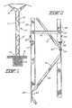
- the pole is comprised essentially of a pair of upright metal channel members 11 and 11' which are interconnected in substantially parallel relationship by a plurality of inwardly disposed braces 12 extending diagonally along the length of the pole.
- the base 13 of the pole is secured in a concrete form 14 located beneath a ground surface 15.
- the top end of the pole 10 supports a transmission line mast 16.
- the pole can be used for a multitude of other applications and may be interconnected with like poles to form support columns.
- the channel members 11 and 11' are formed steel channel members having an elongated flat outer wall 17 and transverse opposed structural flanges 18.
- the ends of the structural flanges 18 are provided with a right angled inner lip 19 extending inwardly and parallel to the flat outer wall whereby to provide more structural rigidity to the channel members.
- the top ones of the channel members need not have flanges with inner lips 19 as they are subjected to less loading than the bottom channel members where more structural strength is required.
- the channel members 11 and 11' are interconnected in parallel relationship by a series of diagonally disposed inner braces 12 which are elongated structural bars, herein angle iron bars having a cross-wall 20 formed with right angle sections which are of equal width and form a right angle structure brace.
- the ends of the bars are flattened to form angulated connecting ends 22.
- the connecting ends are provided with one or two, herein one, through bore 23 which is centrally aligned with the apex 21 of the bar.
- each bar 12 is overlapped with a connecting end 22 of an adjacent bar (see Figure 2) and interconnected together by a fastener 24 which extends through aligned bores 23 of overlapped interconnecting ends 22 and a bore 25 provided in the outer wall 17 of the channels 11 and 11', respectively.
- a single bolt fastener secures opposed ends of diagonal braces 12 to the channels with the bars 12 spanning the structural channels 11 and 11' throughout the length of the pole. Therefore, any load on the poles will be transmitted to the connecting points (the bolt connection 24) disposed on opposed walls whereby the channels are not subjected to eccentric loads.
- a pole is constructed by interconnecting two or more pairs of channel members 11 and 11' end-to-end by a telescopic overlap section, as illustrated at 27.
- the telescopic connection simply consists in providing a top pole section which is provided with like channel members 28 and 28', but of smaller size whereby to slide fit inside a top portion of the channels 11 and 11' respectively.
- a plurality of splice bolts 29 would then secure these overlapped ends together.
- Transverse cross braces 30 may also interconnect the channels 11, 11' and 28 and 28' together and solidify the splice.
- the braces 12 are disposed such that a brace 12' spans the splice region 27 to strengthen the joint.
- next diagonal brace 12" extends diagonally across opposed sides of the channel members while the next brace 12" extends diagonally between the other common side of the channel members.
- This pattern provides for a stronger pole section by providing improved torsional resistance and preventing the side wall 17 from bowing out.
- an elongated reinforcing rib 31 may be formed in the outer wall 17 of the channel members 11 and 11' and located centrally thereof, whereby to strengthen the wall 17 and lower pole section.
- the pattern of these braces 12 can vary along the length of the pole dependent of the number of pairs of channel members being interconnected end to end.
- the upper sections of the pole may have all their braces interconnected along a common central plane 26 as illustrated in Figure 3A as this facilitates installation.
- the flanges 18 of the top channel members need not have a right angle inner lip 19 as shown in Figure 3B, as this section of the pole is subjected to less stress.
- Some of the channel members 11 and 11' may also be provided with interspaced series of three holes 32 (see Figure 4) for attachment of the braces 12 in any desired abovementioned configuration.
- the space holes 32 may be used to attach auxiliary equipment to the pole, such as guy wires, transformers, platforms (not shown), etc.
- poles can be strengthed by the configuration of the serially interconnected braces which span the opposed channel members internally of the pole.
- a still further advantage of this pole is that it is of more pleasing aesthetic design which is an advantage when a pole line extends through a residential community.
Landscapes
- Engineering & Computer Science (AREA)
- Architecture (AREA)
- Civil Engineering (AREA)
- Materials Engineering (AREA)
- Wood Science & Technology (AREA)
- Chemical & Material Sciences (AREA)
- Life Sciences & Earth Sciences (AREA)
- Structural Engineering (AREA)
- Joining Of Building Structures In Genera (AREA)
- Rod-Shaped Construction Members (AREA)
- Electric Cable Installation (AREA)
- Iron Core Of Rotating Electric Machines (AREA)
- Transition And Organic Metals Composition Catalysts For Addition Polymerization (AREA)
- Laying Of Electric Cables Or Lines Outside (AREA)
- Control Of Transmission Device (AREA)
Claims (6)
dadurch gekennzeichnet, daß die Ränder (18) der beiden U-förmigen Elemente (11, 11') eine sich nach innen und parallel zu derflachen Außenwand erstreckende rechtwinklige innere Lippe (19) besitzen und die inneren Verstrebungen (12) rechtwinklige Wände (20) von gleicher Breite aufweisen, wobei innere Verstrebungen (12', 12'") in mindestens einem unteren Abschnitt des Mastes diagonal über die jeweils gegenüberliegenden Seiten der U-förmigen Elemente verbunden sind, wobei sich eine diagonale Zwischenstrebe (12") diagonal über die gegenüberliegenden Seiten der U-förmigen Elemente erstreckt und mit den Enden der Verstrebungen an den gegenüberliegenden Seiten der U-förmigen Elementen verbunden ist und ein unteres der Paare von verbundenen U-förmigen Elementen mit einer länglichen Rippe (31) versehen ist, welche in der flachen Außenwand längs angeordnet und damit integriert ausgebildet ist.
Priority Applications (1)
| Application Number | Priority Date | Filing Date | Title |
|---|---|---|---|
| AT85400676T ATE49621T1 (de) | 1984-12-13 | 1985-04-04 | Maststruktur mit innerer diagonalverstrebung. |
Applications Claiming Priority (2)
| Application Number | Priority Date | Filing Date | Title |
|---|---|---|---|
| CA000470035A CA1235279A (en) | 1984-12-13 | 1984-12-13 | Pole structure with diagonal inner bracing |
| CA470035 | 1984-12-13 |
Publications (3)
| Publication Number | Publication Date |
|---|---|
| EP0184947A2 EP0184947A2 (de) | 1986-06-18 |
| EP0184947A3 EP0184947A3 (en) | 1987-04-29 |
| EP0184947B1 true EP0184947B1 (de) | 1990-01-17 |
Family
ID=4129374
Family Applications (1)
| Application Number | Title | Priority Date | Filing Date |
|---|---|---|---|
| EP85400676A Expired - Lifetime EP0184947B1 (de) | 1984-12-13 | 1985-04-04 | Maststruktur mit innerer Diagonalverstrebung |
Country Status (8)
| Country | Link |
|---|---|
| EP (1) | EP0184947B1 (de) |
| JP (1) | JPS61142266A (de) |
| AT (1) | ATE49621T1 (de) |
| CA (1) | CA1235279A (de) |
| DE (1) | DE3575445D1 (de) |
| ES (1) | ES296035Y (de) |
| IN (1) | IN163205B (de) |
| OA (1) | OA08021A (de) |
Families Citing this family (1)
| Publication number | Priority date | Publication date | Assignee | Title |
|---|---|---|---|---|
| GB2237589B (en) * | 1989-11-03 | 1994-03-02 | Stanley Ovington | Improvements in fence posts |
Family Cites Families (5)
| Publication number | Priority date | Publication date | Assignee | Title |
|---|---|---|---|---|
| GB378635A (en) * | 1931-08-05 | 1932-08-18 | Callenders Cable & Const Co | Improvements in poles for the support of electric transmission lines |
| US2075772A (en) * | 1935-08-09 | 1937-03-30 | United States Gypsum Co | Stud or joist |
| GB628868A (en) * | 1947-05-08 | 1949-09-06 | Calum Grant And Partners Ltd | Improvements in the construction of metal posts or masts |
| GB1073674A (en) * | 1966-01-14 | 1967-06-28 | Painter Brothers Ltd | Improvements in metal lattice structures |
| CA1073632A (en) * | 1978-06-05 | 1980-03-18 | Igor W. Geba | Semi-lattice pole |
-
1984
- 1984-12-13 CA CA000470035A patent/CA1235279A/en not_active Expired
-
1985
- 1985-01-22 IN IN51/MAS/85A patent/IN163205B/en unknown
- 1985-04-04 DE DE8585400676T patent/DE3575445D1/de not_active Expired - Lifetime
- 1985-04-04 AT AT85400676T patent/ATE49621T1/de not_active IP Right Cessation
- 1985-04-04 EP EP85400676A patent/EP0184947B1/de not_active Expired - Lifetime
- 1985-04-30 ES ES1985296035U patent/ES296035Y/es not_active Expired
- 1985-05-17 OA OA58596A patent/OA08021A/xx unknown
- 1985-06-05 JP JP60120723A patent/JPS61142266A/ja active Pending
Also Published As
| Publication number | Publication date |
|---|---|
| JPS61142266A (ja) | 1986-06-30 |
| ATE49621T1 (de) | 1990-02-15 |
| IN163205B (de) | 1988-08-20 |
| EP0184947A2 (de) | 1986-06-18 |
| EP0184947A3 (en) | 1987-04-29 |
| ES296035Y (es) | 1988-01-16 |
| ES296035U (es) | 1987-07-16 |
| DE3575445D1 (de) | 1990-02-22 |
| CA1235279A (en) | 1988-04-19 |
| OA08021A (en) | 1986-01-31 |
Similar Documents
| Publication | Publication Date | Title |
|---|---|---|
| US4934114A (en) | Lightweight line tower kit | |
| US11536018B2 (en) | Frame for sectional foldable prefabricated building | |
| US4315386A (en) | Portal building structures | |
| US4525975A (en) | Modular high rise construction utilizing assembly line modules | |
| US3368319A (en) | Tall column structure of connected sections with warren cross-bracing and legs of channel section | |
| US6745539B1 (en) | Lattice tower | |
| US4483117A (en) | Composite gambrel roof truss with prefabricated truss components | |
| WO2001046531A3 (en) | Modular building frame | |
| US5117607A (en) | Sectional hollow metal pole structure | |
| US4201021A (en) | Building frame construction | |
| US3818671A (en) | Frame structure | |
| US5325644A (en) | Pool wall construction | |
| US3676964A (en) | Frame and building structure and method of constructing same | |
| CA1235279A (en) | Pole structure with diagonal inner bracing | |
| US4506487A (en) | Steel truss | |
| US20060185296A1 (en) | Solid structure | |
| DE4027137C2 (de) | Raumzelle | |
| GB2085507A (en) | Buildings | |
| JP2823721B2 (ja) | 保護用シェッド | |
| EP0393091B1 (de) | Lasttragendes waagerechtes struktürsystem für ein gebäude | |
| JPH06280382A (ja) | 組立足場ユニット | |
| KR200417902Y1 (ko) | 타워 크레인의 앵커 프레임 조립체 | |
| US5581961A (en) | Portal frame system | |
| KR102916304B1 (ko) | 관형주 철탑용 내구성 강화 관재 | |
| KR100668593B1 (ko) | 타워 크레인의 앵커 프레임 조립체 |
Legal Events
| Date | Code | Title | Description |
|---|---|---|---|
| PUAI | Public reference made under article 153(3) epc to a published international application that has entered the european phase |
Free format text: ORIGINAL CODE: 0009012 |
|
| AK | Designated contracting states |
Kind code of ref document: A2 Designated state(s): AT BE CH DE FR GB IT LI LU NL SE |
|
| RAP1 | Party data changed (applicant data changed or rights of an application transferred) |
Owner name: TRI-STEEL INC. |
|
| PUAL | Search report despatched |
Free format text: ORIGINAL CODE: 0009013 |
|
| AK | Designated contracting states |
Kind code of ref document: A3 Designated state(s): AT BE CH DE FR GB IT LI LU NL SE |
|
| 17P | Request for examination filed |
Effective date: 19871009 |
|
| 17Q | First examination report despatched |
Effective date: 19880712 |
|
| GRAA | (expected) grant |
Free format text: ORIGINAL CODE: 0009210 |
|
| AK | Designated contracting states |
Kind code of ref document: B1 Designated state(s): AT BE CH DE FR GB IT LI LU NL SE |
|
| REF | Corresponds to: |
Ref document number: 49621 Country of ref document: AT Date of ref document: 19900215 Kind code of ref document: T |
|
| ITF | It: translation for a ep patent filed | ||
| REF | Corresponds to: |
Ref document number: 3575445 Country of ref document: DE Date of ref document: 19900222 |
|
| ET | Fr: translation filed | ||
| PLBE | No opposition filed within time limit |
Free format text: ORIGINAL CODE: 0009261 |
|
| STAA | Information on the status of an ep patent application or granted ep patent |
Free format text: STATUS: NO OPPOSITION FILED WITHIN TIME LIMIT |
|
| 26N | No opposition filed | ||
| PGFP | Annual fee paid to national office [announced via postgrant information from national office to epo] |
Ref country code: SE Payment date: 19910118 Year of fee payment: 7 |
|
| PGFP | Annual fee paid to national office [announced via postgrant information from national office to epo] |
Ref country code: LU Payment date: 19910206 Year of fee payment: 7 |
|
| PGFP | Annual fee paid to national office [announced via postgrant information from national office to epo] |
Ref country code: CH Payment date: 19910313 Year of fee payment: 7 |
|
| PGFP | Annual fee paid to national office [announced via postgrant information from national office to epo] |
Ref country code: GB Payment date: 19910321 Year of fee payment: 7 |
|
| PGFP | Annual fee paid to national office [announced via postgrant information from national office to epo] |
Ref country code: AT Payment date: 19910328 Year of fee payment: 7 |
|
| PGFP | Annual fee paid to national office [announced via postgrant information from national office to epo] |
Ref country code: BE Payment date: 19910425 Year of fee payment: 7 |
|
| ITTA | It: last paid annual fee | ||
| PGFP | Annual fee paid to national office [announced via postgrant information from national office to epo] |
Ref country code: NL Payment date: 19910430 Year of fee payment: 7 |
|
| PGFP | Annual fee paid to national office [announced via postgrant information from national office to epo] |
Ref country code: DE Payment date: 19910528 Year of fee payment: 7 |
|
| EPTA | Lu: last paid annual fee | ||
| PG25 | Lapsed in a contracting state [announced via postgrant information from national office to epo] |
Ref country code: LU Free format text: LAPSE BECAUSE OF NON-PAYMENT OF DUE FEES Effective date: 19920404 Ref country code: GB Effective date: 19920404 Ref country code: AT Effective date: 19920404 |
|
| PG25 | Lapsed in a contracting state [announced via postgrant information from national office to epo] |
Ref country code: SE Effective date: 19920405 |
|
| PGFP | Annual fee paid to national office [announced via postgrant information from national office to epo] |
Ref country code: FR Payment date: 19920417 Year of fee payment: 8 |
|
| PG25 | Lapsed in a contracting state [announced via postgrant information from national office to epo] |
Ref country code: LI Effective date: 19920430 Ref country code: CH Effective date: 19920430 Ref country code: BE Effective date: 19920430 |
|
| BERE | Be: lapsed |
Owner name: TRI-STEEL INC. Effective date: 19920430 |
|
| PG25 | Lapsed in a contracting state [announced via postgrant information from national office to epo] |
Ref country code: NL Effective date: 19921101 |
|
| GBPC | Gb: european patent ceased through non-payment of renewal fee | ||
| NLV4 | Nl: lapsed or anulled due to non-payment of the annual fee | ||
| REG | Reference to a national code |
Ref country code: CH Ref legal event code: PL |
|
| PG25 | Lapsed in a contracting state [announced via postgrant information from national office to epo] |
Ref country code: DE Effective date: 19930101 |
|
| PG25 | Lapsed in a contracting state [announced via postgrant information from national office to epo] |
Ref country code: FR Effective date: 19931229 |
|
| REG | Reference to a national code |
Ref country code: FR Ref legal event code: ST |
|
| EUG | Se: european patent has lapsed |
Ref document number: 85400676.4 Effective date: 19921108 |