EP0184952A1 - Luftregenerator mittels eines Venturis mit Sauerstoffstrahl - Google Patents
Luftregenerator mittels eines Venturis mit Sauerstoffstrahl Download PDFInfo
- Publication number
- EP0184952A1 EP0184952A1 EP85402173A EP85402173A EP0184952A1 EP 0184952 A1 EP0184952 A1 EP 0184952A1 EP 85402173 A EP85402173 A EP 85402173A EP 85402173 A EP85402173 A EP 85402173A EP 0184952 A1 EP0184952 A1 EP 0184952A1
- Authority
- EP
- European Patent Office
- Prior art keywords
- nozzle
- diameter
- venturi
- air
- oxygen
- Prior art date
- Legal status (The legal status is an assumption and is not a legal conclusion. Google has not performed a legal analysis and makes no representation as to the accuracy of the status listed.)
- Granted
Links
- QVGXLLKOCUKJST-UHFFFAOYSA-N atomic oxygen Chemical compound [O] QVGXLLKOCUKJST-UHFFFAOYSA-N 0.000 title claims abstract description 31
- 229910052760 oxygen Inorganic materials 0.000 title claims abstract description 31
- 239000001301 oxygen Substances 0.000 title claims abstract description 31
- CURLTUGMZLYLDI-UHFFFAOYSA-N Carbon dioxide Chemical compound O=C=O CURLTUGMZLYLDI-UHFFFAOYSA-N 0.000 claims description 8
- 239000010979 ruby Substances 0.000 claims description 7
- 229910001750 ruby Inorganic materials 0.000 claims description 7
- 238000011144 upstream manufacturing Methods 0.000 claims description 6
- 229910002092 carbon dioxide Inorganic materials 0.000 claims description 4
- 239000001569 carbon dioxide Substances 0.000 claims description 4
- 229910052782 aluminium Inorganic materials 0.000 claims description 2
- XAGFODPZIPBFFR-UHFFFAOYSA-N aluminium Chemical compound [Al] XAGFODPZIPBFFR-UHFFFAOYSA-N 0.000 claims description 2
- 229910052790 beryllium Inorganic materials 0.000 claims description 2
- 229910052594 sapphire Inorganic materials 0.000 claims description 2
- 239000010980 sapphire Substances 0.000 claims description 2
- 210000000078 claw Anatomy 0.000 claims 1
- 239000000463 material Substances 0.000 claims 1
- 229910052751 metal Inorganic materials 0.000 claims 1
- 239000002184 metal Substances 0.000 claims 1
- 238000001914 filtration Methods 0.000 abstract 1
- 239000007789 gas Substances 0.000 description 6
- MYMOFIZGZYHOMD-UHFFFAOYSA-N Dioxygen Chemical compound O=O MYMOFIZGZYHOMD-UHFFFAOYSA-N 0.000 description 4
- 230000002745 absorbent Effects 0.000 description 3
- 239000002250 absorbent Substances 0.000 description 3
- 238000005315 distribution function Methods 0.000 description 3
- 230000000694 effects Effects 0.000 description 3
- 238000005259 measurement Methods 0.000 description 3
- XLYOFNOQVPJJNP-UHFFFAOYSA-N water Substances O XLYOFNOQVPJJNP-UHFFFAOYSA-N 0.000 description 3
- RYGMFSIKBFXOCR-UHFFFAOYSA-N Copper Chemical compound [Cu] RYGMFSIKBFXOCR-UHFFFAOYSA-N 0.000 description 1
- 238000013019 agitation Methods 0.000 description 1
- 238000004364 calculation method Methods 0.000 description 1
- 229910052802 copper Inorganic materials 0.000 description 1
- 239000010949 copper Substances 0.000 description 1
- 238000002788 crimping Methods 0.000 description 1
- 230000014509 gene expression Effects 0.000 description 1
- 238000009434 installation Methods 0.000 description 1
- 238000005511 kinetic theory Methods 0.000 description 1
- 239000007788 liquid Substances 0.000 description 1
- 239000000203 mixture Substances 0.000 description 1
- 230000029058 respiratory gaseous exchange Effects 0.000 description 1
- 230000007704 transition Effects 0.000 description 1
- 238000003466 welding Methods 0.000 description 1
Images

Classifications
-
- F—MECHANICAL ENGINEERING; LIGHTING; HEATING; WEAPONS; BLASTING
- F24—HEATING; RANGES; VENTILATING
- F24F—AIR-CONDITIONING; AIR-HUMIDIFICATION; VENTILATION; USE OF AIR CURRENTS FOR SCREENING
- F24F13/00—Details common to, or for air-conditioning, air-humidification, ventilation or use of air currents for screening
- F24F13/26—Arrangements for air-circulation by means of induction, e.g. by fluid coupling or thermal effect
-
- F—MECHANICAL ENGINEERING; LIGHTING; HEATING; WEAPONS; BLASTING
- F04—POSITIVE - DISPLACEMENT MACHINES FOR LIQUIDS; PUMPS FOR LIQUIDS OR ELASTIC FLUIDS
- F04F—PUMPING OF FLUID BY DIRECT CONTACT OF ANOTHER FLUID OR BY USING INERTIA OF FLUID TO BE PUMPED; SIPHONS
- F04F5/00—Jet pumps, i.e. devices in which flow is induced by pressure drop caused by velocity of another fluid flow
- F04F5/44—Component parts, details, or accessories not provided for in, or of interest apart from, groups F04F5/02 - F04F5/42
- F04F5/46—Arrangements of nozzles
Definitions
- the present invention relates to individual air regenerators or for collective premises, absorbing carbon dioxide under the effect of a Venturi ensuring the suction of air through the cartridge by means of a nozzle placed in the axis of Venturi and connected to a pressurized oxygen reserve.
- the quantity of regenerated air When it comes to supplying regenerated air to a closed enclosure, such as premises or cockpits, the quantity of regenerated air must correspond to a minimum ensuring the personnel therein an amount of breathable air allowing a certain expenditure of energy, for example for the execution in the confined space of certain works. It is accepted that such an activity, for example of the order of 100 watts, requires a minimum supply of 37 liters of regenerated air per minute per person.
- Respirators of the aforementioned type operating without any energy input to ensure the suction of stale air through the absorbent cartridge other than that of the expansion energy of compressed oxygen injected into the Venturi, consume 1 liter of oxygen at atmospheric pressure, which leads to a minimum volumetric yield: Q 2 and Q 1 being respectively the quantity of regenerated air and the quantity of oxygen injected in liters.
- the present invention is based on the discovery of the extraordinarily high potential for air entrainment using Venturi that presents an oxygen jet whose molecules are reoriented and whose speed distribution becomes anisotropic and does not follow the function Maxwell distribution.
- f (rwt) being the simple speed distribution function.
- a speed distribution function is anisotropic, if it only depends on the module of w and not on its orientation.
- the gas in the classical calculation of injectors, we consider the gas as a perfect gas, that is to say a gas whose molecules have an isotropic distribution in direction and a Maxwellian distribution of speeds. These conditions are approximately fulfilled, when the nozzle duct is cylindrical, of a great length compared to its diameter. The pressure drop in the duct is then large compared to that in the outlet end or nozzle and the expansion energy is mainly used to heat the oxygen cooled by its expansion.
- the volumetric efficiency easily exceeds the efficiency of 37, which provides a minimum volume of regenerated air to personnel working in a closed enclosure.
- This increased potential to entrain large amounts of air through the Venturi can be explained by the fact that in a jet of oriented molecules there are few side collisions between the oxygen molecules and that all of the energy dissipated in lateral collisions will be dissipated in collisions with the entrained air, thus giving a good volumetric efficiency of the Venturi.
- the carbon dioxide absorbent cartridge air regenerator comprising a Venturi ensuring the suction of air through the cartridge by means of a nozzle opening axially upstream of the narrowed section of the Venturi and connected to an oxygen reserve under pressure according to the invention
- the nozzle of the nozzle is constituted by a relatively thin wall, in which a calibrated orifice is pierced and whose thickness at the location of the bore is at most equal to the diameter of the orifice, so that at the exit of the nozzle the molecules of the oxygen jet are reoriented and the distribution of their speeds becomes anisotropic different from the distribution according to the Maxwell function.
- a jet of oxygen with reoriented molecules can be produced by means of a nozzle constituted by a relatively large tube, for example of 2 mm in diameter ending in a nozzle formed by a calibrated orifice of clear contour with a diameter of 0 , 15 to 0.25 mm drilled in a relatively thin wall, for example 0.01 mm thick.
- Such a wall pierced with an orifice can be produced in a metallic sheet of copper or aluminum, which is pierced using a suitable tool.
- Another way of making the nozzle consists in crimping at the end of the tube a clockwork clasp in ruby, sapphire or cupro-beryllium, the flat face of which faces outwards and which is pierced with a central orifice. whose diameter varies between 0.15 and 0.25 mm.
- the Venturi used can be of variable shape. They can be symmetrical with the inlet and outlet horns of the same length or asymmetrical, the outlet horn being longer than the inlet horn.
- the oxygen supply pressure is not a critical element, very acceptable volumetric yields are obtained in the pressure range of 0.5 to 2 bars.
- Tests have shown that there is a critical relationship between the diameter of the narrowed section of the Venturi and the distance at which the nozzle of the nozzle is placed upstream of the narrowed section of the Venturi, for a given oxygen pressure.
- this distance is such that the diameter of the section of the oxygen jet, measured in the open air, at the location of the narrowed section of the Venturi is substantially equal to the diameter of this section.
- the jet is directed perpendicularly to a target formed by a surface of water covering a white screen immersed in a few centimeters of water.
- the vacuum of the surface under the oxygen jet is observed and its diameter is measured, when a beam of light parallel to the screen is sent through the liquid.
- the depression creates a shadow circle on the screen, the diameter of which varies with the flow rate of the nozzle and the distance from the nozzle to the water surface.
- this control system it is possible to determine the distance from the nozzle of the nozzle of the narrowed section as a function of the pressure of the oxygen flow rate so that the diameter of the section of the jet thus measured in the open air is substantially equal to the location of the narrowed section of the Venturi to the diameter of this section.
- the air regenerator shown comprises a cylindrical duct 4 closed from below, in which is placed a Venturi 1 whose outlet horn 1a is fixed inside the duct 4 by welding and is connected to an outlet pipe 3 regenerated air.
- the opposite wall of the duct 4 is in the form of a disc pierced with a central opening for the passage of a nozzle 2 connected via a duct 8 to the regulator of a cylinder of compressed oxygen.
- the end of the inlet horn 1b is open and opens freely inside the cylindrical duct 4.
- This duct communicates with two filter cartridges 5 for absorbing carbon dioxide, arranged on either side of the cylindrical duct 4.
- the cartridges 5 are fixed in a removable manner by application with pressure on a plastic seal.
- the nozzle 2 has a nozzle shown in FIG. 2.
- a nozzle 10 provided with a circular shoulder 11 intended to bear on a support 12, ends in a narrowed section at the end of which is set a ruby 13.
- This watch ruby is cut so as to present a flat face 14 to which opens a calibrated orifice 1 5 of 0.20 mm in diameter.
- the inner face of the ruby is cut so as to have a hollow 16, which reduces its thickness at the location of the hole to 0.20 mm.
- the Venturi used is asymmetrical in shape. Its very flared entry horn measures 20 mm, its conical exit horn 60 mm long ends with a 30 mm diameter flare. The diameter of the narrowed section of the Venturi is 12 mm.
- the internal diameter of the nozzle at the point of section shrinkage is 2 mm.
- the thickness of the ruby at the location of the hole is 0.2 mm.
- the oxygen expansion at the narrowing of the Venturi causes a vacuum upstream which has the effect of sucking the polluted air through the cartridges, passing it inside the Venturi where it mixes with oxygen and let out through the tube 3 a mixture of purified air and pure oxygen.
- the pressure drop caused by the mounting of an absorbent cartridge lowers the volumetric efficiency by 10%, the end piece intended for the other cartridge being blocked.
- the yield only drops by 5% when two cartridges are fitted.
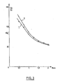
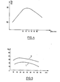
- the two curves 1 and 2 represent the variations in the regenerated air flow Q 2 with the distance from the nozzle of the narrowed section of the Venturi for a Venturi whose narrowed section has a diameter of 12 mm and for oxygen flows of 1 bar (curve 1) and 2 bars (curve 2).
- the optimum flow is between 20 and 40 mm apart.
- the device according to the invention constitutes an undeniable progress in the field of the supply of regenerated air in a closed enclosure, because it makes it possible to produce an increased supply and largely sufficient to ensure the breathing comfort of the people who are there in the by means of a device of small bulk without any external energy supply other than that of expansion of a cylinder of compressed oxygen.
Landscapes
- Engineering & Computer Science (AREA)
- Mechanical Engineering (AREA)
- General Engineering & Computer Science (AREA)
- Physics & Mathematics (AREA)
- Fluid Mechanics (AREA)
- Chemical & Material Sciences (AREA)
- Combustion & Propulsion (AREA)
- Respiratory Apparatuses And Protective Means (AREA)
- Oxygen, Ozone, And Oxides In General (AREA)
- Separation By Low-Temperature Treatments (AREA)
- Pharmaceuticals Containing Other Organic And Inorganic Compounds (AREA)
- Percussion Or Vibration Massage (AREA)
Priority Applications (1)
| Application Number | Priority Date | Filing Date | Title |
|---|---|---|---|
| AT85402173T ATE27855T1 (de) | 1984-11-13 | 1985-11-12 | Luftregenerator mittels eines venturis mit sauerstoffstrahl. |
Applications Claiming Priority (2)
| Application Number | Priority Date | Filing Date | Title |
|---|---|---|---|
| FR8417308A FR2573181B1 (fr) | 1984-11-13 | 1984-11-13 | Regenerateur d'air au moyen d'un venturi a jet d'oxygene |
| FR8417308 | 1984-11-13 |
Publications (2)
| Publication Number | Publication Date |
|---|---|
| EP0184952A1 true EP0184952A1 (de) | 1986-06-18 |
| EP0184952B1 EP0184952B1 (de) | 1987-06-16 |
Family
ID=9309552
Family Applications (1)
| Application Number | Title | Priority Date | Filing Date |
|---|---|---|---|
| EP85402173A Expired EP0184952B1 (de) | 1984-11-13 | 1985-11-12 | Luftregenerator mittels eines Venturis mit Sauerstoffstrahl |
Country Status (5)
| Country | Link |
|---|---|
| US (1) | US4632678A (de) |
| EP (1) | EP0184952B1 (de) |
| AT (1) | ATE27855T1 (de) |
| DE (1) | DE3560269D1 (de) |
| FR (1) | FR2573181B1 (de) |
Families Citing this family (11)
| Publication number | Priority date | Publication date | Assignee | Title |
|---|---|---|---|---|
| US4971609A (en) * | 1990-02-05 | 1990-11-20 | Pawlos Robert A | Portable oxygen concentrator |
| FR2731693B1 (fr) * | 1995-03-16 | 1997-05-23 | Air Liquide | Procede et installation de generation d'azote pour le traitement thermique |
| EP1931432A4 (de) * | 2005-09-09 | 2009-07-22 | Essex P B & R Corp | Atemschutzgerät |
| WO2007112482A1 (en) * | 2006-03-31 | 2007-10-11 | Shairzal Safety Engineering Pty Ltd | Passive apparatus and method for filtering noxious gases |
| CN101622034B (zh) * | 2007-03-09 | 2013-06-12 | 斯特拉塔产品全球有限责任公司 | 用于净化空气的设备、系统及方法 |
| CN101925722A (zh) * | 2008-07-21 | 2010-12-22 | 杰拉尔德·约翰·内斯 | 自含式避难峒室 |
| CN101858899A (zh) * | 2010-05-14 | 2010-10-13 | 上海思达分析仪器有限责任公司 | 氢火焰离子化检测器的极化结构 |
| TWI459981B (zh) * | 2012-04-09 | 2014-11-11 | Galemed Corp | Air intake device |
| DE202012103366U1 (de) * | 2012-09-04 | 2012-10-08 | WS - Wärmeprozesstechnik GmbH | Strahlungsheizrohr |
| CN105805910B (zh) * | 2015-08-26 | 2019-08-16 | 深圳创新设计研究院有限公司 | 空调器及其送风装置 |
| CN105805911B (zh) * | 2015-08-26 | 2019-01-15 | 深圳创新设计研究院有限公司 | 空调器及其送风装置 |
Citations (2)
| Publication number | Priority date | Publication date | Assignee | Title |
|---|---|---|---|---|
| NL264397A (de) * | 1960-05-05 | |||
| FR1319246A (fr) * | 1960-04-25 | 1963-02-22 | Luwa Ag | Appareil de climatisation de locaux |
Family Cites Families (4)
| Publication number | Priority date | Publication date | Assignee | Title |
|---|---|---|---|---|
| US3696588A (en) * | 1970-12-07 | 1972-10-10 | Ingersoll Rand Co | Gas drying apparatus and method |
| US3934989A (en) * | 1973-03-12 | 1976-01-27 | Ingersoll-Rand Company | Gas drying apparatus |
| US3834136A (en) * | 1973-04-10 | 1974-09-10 | Ingersoll Rand Co | Gas drying apparatus and method |
| US4542114A (en) * | 1982-08-03 | 1985-09-17 | Air Products And Chemicals, Inc. | Process for the recovery and recycle of effluent gas from the regeneration of particulate matter with oxygen and carbon dioxide |
-
1984
- 1984-11-13 FR FR8417308A patent/FR2573181B1/fr not_active Expired
-
1985
- 1985-11-12 DE DE8585402173T patent/DE3560269D1/de not_active Expired
- 1985-11-12 AT AT85402173T patent/ATE27855T1/de not_active IP Right Cessation
- 1985-11-12 EP EP85402173A patent/EP0184952B1/de not_active Expired
- 1985-11-13 US US06/797,591 patent/US4632678A/en not_active Expired - Fee Related
Patent Citations (2)
| Publication number | Priority date | Publication date | Assignee | Title |
|---|---|---|---|---|
| FR1319246A (fr) * | 1960-04-25 | 1963-02-22 | Luwa Ag | Appareil de climatisation de locaux |
| NL264397A (de) * | 1960-05-05 |
Non-Patent Citations (1)
| Title |
|---|
| TRANSACTIONS OF THE A.S.M.E. JOURNAL OF ENGINEERING FOR INDUSTRY, vol. 105, no. 1, février 1983, pages 54-59, New York, US; P.G. SEXTON et al.: "Computer simulation of breathing systems for divers" * |
Also Published As
| Publication number | Publication date |
|---|---|
| FR2573181B1 (fr) | 1987-01-23 |
| EP0184952B1 (de) | 1987-06-16 |
| FR2573181A1 (fr) | 1986-05-16 |
| US4632678A (en) | 1986-12-30 |
| ATE27855T1 (de) | 1987-07-15 |
| DE3560269D1 (en) | 1987-07-23 |
Similar Documents
| Publication | Publication Date | Title |
|---|---|---|
| EP0184952B1 (de) | Luftregenerator mittels eines Venturis mit Sauerstoffstrahl | |
| FR2687540A1 (fr) | Appareil d'irrigation goutte a goutte. | |
| FR2581284A1 (fr) | Buse composite pour un chalumeau a arc-plasma | |
| FR3019989B1 (fr) | Diffuseur de fumee et atomiseur | |
| FR2588662A1 (fr) | Collecteur de poussiere, a fixer aux habits d'une personne. | |
| FR2697287A1 (fr) | Diffuseur d'échappement de turbine à gaz. | |
| CA1197107A (fr) | Dispositif de regulation d'un refrigerateur a effet joule-thomson | |
| EP0263031B1 (de) | Induktiv gekoppelte Luft-Plasma-Vorrichtung für die spektrometrische Analyse von Elementen | |
| FR2550453A1 (fr) | Ensemble combine a diffuseur a venturi et valve d'exhalation | |
| EP0236208A1 (de) | Unterwasser-Atmungsgerät für zusammengepresste Luft | |
| FR2793873A1 (fr) | Conduit de succion de gaz pour un compresseur de refrigeration | |
| FR2631441A1 (fr) | Debitmetre a double vortex bloque | |
| FR2496520A1 (fr) | Perfectionnements apportes aux chalumeaux oxy-acetyleniques | |
| WO2007006987A1 (fr) | Extincteur a brouillard de liquide et son utilisation | |
| CH641916A5 (fr) | Appareil laser a gaz et a recirculation d'ecoulement. | |
| FR2787352A1 (fr) | Dispositif de pulverisation de gouttelettes muni d'un tube d'extraction | |
| FR3127866A1 (fr) | Dispositif pour goûter des e-liquides | |
| BE1004612A6 (fr) | Dispositif de prechauffage d'une busette de coulee d'un metal en fusion. | |
| FR2462553A1 (fr) | Silencieux pour gaz d'echappement | |
| BE876956A (fr) | Dispositif de soufflage a niveau de bruit bas | |
| FR2519254A1 (fr) | Dispositif de circulation d'air a double courant module dans les alveoles pulmonaires | |
| FR2546126A1 (fr) | Appareil respiratoire de plongee a circuit semi-ferme | |
| EP0581636B1 (de) | Stromverbesserer für eine Entspannungsstation und Messvorrichtung | |
| FR2500911A1 (fr) | Bruleur a huile et oxygene | |
| FR2580167A1 (fr) | Systeme de commande de la pulverisation d'un liquide a l'extremite d'un instrument dentaire |
Legal Events
| Date | Code | Title | Description |
|---|---|---|---|
| PUAI | Public reference made under article 153(3) epc to a published international application that has entered the european phase |
Free format text: ORIGINAL CODE: 0009012 |
|
| 17P | Request for examination filed |
Effective date: 19851118 |
|
| AK | Designated contracting states |
Kind code of ref document: A1 Designated state(s): AT BE CH DE GB IT LI LU NL SE |
|
| 17Q | First examination report despatched |
Effective date: 19861124 |
|
| ITF | It: translation for a ep patent filed | ||
| GRAA | (expected) grant |
Free format text: ORIGINAL CODE: 0009210 |
|
| AK | Designated contracting states |
Kind code of ref document: B1 Designated state(s): AT BE CH DE GB IT LI LU NL SE |
|
| REF | Corresponds to: |
Ref document number: 27855 Country of ref document: AT Date of ref document: 19870715 Kind code of ref document: T |
|
| REF | Corresponds to: |
Ref document number: 3560269 Country of ref document: DE Date of ref document: 19870723 |
|
| PG25 | Lapsed in a contracting state [announced via postgrant information from national office to epo] |
Ref country code: LU Free format text: LAPSE BECAUSE OF NON-PAYMENT OF DUE FEES Effective date: 19871130 |
|
| PLBE | No opposition filed within time limit |
Free format text: ORIGINAL CODE: 0009261 |
|
| STAA | Information on the status of an ep patent application or granted ep patent |
Free format text: STATUS: NO OPPOSITION FILED WITHIN TIME LIMIT |
|
| 26N | No opposition filed | ||
| PGFP | Annual fee paid to national office [announced via postgrant information from national office to epo] |
Ref country code: SE Payment date: 19891004 Year of fee payment: 5 |
|
| PGFP | Annual fee paid to national office [announced via postgrant information from national office to epo] |
Ref country code: LU Payment date: 19891011 Year of fee payment: 5 |
|
| PGFP | Annual fee paid to national office [announced via postgrant information from national office to epo] |
Ref country code: BE Payment date: 19891020 Year of fee payment: 5 |
|
| PGFP | Annual fee paid to national office [announced via postgrant information from national office to epo] |
Ref country code: CH Payment date: 19891026 Year of fee payment: 5 |
|
| PGFP | Annual fee paid to national office [announced via postgrant information from national office to epo] |
Ref country code: AT Payment date: 19891128 Year of fee payment: 5 |
|
| ITTA | It: last paid annual fee | ||
| PGFP | Annual fee paid to national office [announced via postgrant information from national office to epo] |
Ref country code: NL Payment date: 19891130 Year of fee payment: 5 Ref country code: GB Payment date: 19891130 Year of fee payment: 5 |
|
| PGFP | Annual fee paid to national office [announced via postgrant information from national office to epo] |
Ref country code: DE Payment date: 19900118 Year of fee payment: 5 |
|
| PG25 | Lapsed in a contracting state [announced via postgrant information from national office to epo] |
Ref country code: GB Effective date: 19901112 Ref country code: AT Effective date: 19901112 |
|
| PG25 | Lapsed in a contracting state [announced via postgrant information from national office to epo] |
Ref country code: SE Effective date: 19901113 |
|
| PG25 | Lapsed in a contracting state [announced via postgrant information from national office to epo] |
Ref country code: LI Effective date: 19901130 Ref country code: CH Effective date: 19901130 Ref country code: BE Effective date: 19901130 |
|
| BERE | Be: lapsed |
Owner name: GOMEZ RUBEN Effective date: 19901130 Owner name: BAUMERT CHARLES Effective date: 19901130 |
|
| PG25 | Lapsed in a contracting state [announced via postgrant information from national office to epo] |
Ref country code: NL Effective date: 19910601 |
|
| GBPC | Gb: european patent ceased through non-payment of renewal fee | ||
| NLV4 | Nl: lapsed or anulled due to non-payment of the annual fee | ||
| REG | Reference to a national code |
Ref country code: CH Ref legal event code: PL |
|
| PG25 | Lapsed in a contracting state [announced via postgrant information from national office to epo] |
Ref country code: DE Effective date: 19910801 |
|
| EUG | Se: european patent has lapsed |
Ref document number: 85402173.0 Effective date: 19910705 |