EP0184955A1 - Correcteur de freinage asservi à la décélération - Google Patents
Correcteur de freinage asservi à la décélération Download PDFInfo
- Publication number
- EP0184955A1 EP0184955A1 EP85402194A EP85402194A EP0184955A1 EP 0184955 A1 EP0184955 A1 EP 0184955A1 EP 85402194 A EP85402194 A EP 85402194A EP 85402194 A EP85402194 A EP 85402194A EP 0184955 A1 EP0184955 A1 EP 0184955A1
- Authority
- EP
- European Patent Office
- Prior art keywords
- mass
- spring means
- chamber
- deceleration
- vehicle
- Prior art date
- Legal status (The legal status is an assumption and is not a legal conclusion. Google has not performed a legal analysis and makes no representation as to the accuracy of the status listed.)
- Granted
Links
Images
Classifications
-
- B—PERFORMING OPERATIONS; TRANSPORTING
- B60—VEHICLES IN GENERAL
- B60T—VEHICLE BRAKE CONTROL SYSTEMS OR PARTS THEREOF; BRAKE CONTROL SYSTEMS OR PARTS THEREOF, IN GENERAL; ARRANGEMENT OF BRAKING ELEMENTS ON VEHICLES IN GENERAL; PORTABLE DEVICES FOR PREVENTING UNWANTED MOVEMENT OF VEHICLES; VEHICLE MODIFICATIONS TO FACILITATE COOLING OF BRAKES
- B60T15/00—Construction arrangement, or operation of valves incorporated in power brake systems and not covered by groups B60T11/00 or B60T13/00
-
- B—PERFORMING OPERATIONS; TRANSPORTING
- B60—VEHICLES IN GENERAL
- B60T—VEHICLE BRAKE CONTROL SYSTEMS OR PARTS THEREOF; BRAKE CONTROL SYSTEMS OR PARTS THEREOF, IN GENERAL; ARRANGEMENT OF BRAKING ELEMENTS ON VEHICLES IN GENERAL; PORTABLE DEVICES FOR PREVENTING UNWANTED MOVEMENT OF VEHICLES; VEHICLE MODIFICATIONS TO FACILITATE COOLING OF BRAKES
- B60T8/00—Arrangements for adjusting wheel-braking force to meet varying vehicular or ground-surface conditions, e.g. limiting or varying distribution of braking force
- B60T8/26—Arrangements for adjusting wheel-braking force to meet varying vehicular or ground-surface conditions, e.g. limiting or varying distribution of braking force characterised by producing differential braking between front and rear wheels
-
- B—PERFORMING OPERATIONS; TRANSPORTING
- B60—VEHICLES IN GENERAL
- B60T—VEHICLE BRAKE CONTROL SYSTEMS OR PARTS THEREOF; BRAKE CONTROL SYSTEMS OR PARTS THEREOF, IN GENERAL; ARRANGEMENT OF BRAKING ELEMENTS ON VEHICLES IN GENERAL; PORTABLE DEVICES FOR PREVENTING UNWANTED MOVEMENT OF VEHICLES; VEHICLE MODIFICATIONS TO FACILITATE COOLING OF BRAKES
- B60T8/00—Arrangements for adjusting wheel-braking force to meet varying vehicular or ground-surface conditions, e.g. limiting or varying distribution of braking force
- B60T8/26—Arrangements for adjusting wheel-braking force to meet varying vehicular or ground-surface conditions, e.g. limiting or varying distribution of braking force characterised by producing differential braking between front and rear wheels
- B60T8/28—Arrangements for adjusting wheel-braking force to meet varying vehicular or ground-surface conditions, e.g. limiting or varying distribution of braking force characterised by producing differential braking between front and rear wheels responsive to deceleration
- B60T8/285—Arrangements for adjusting wheel-braking force to meet varying vehicular or ground-surface conditions, e.g. limiting or varying distribution of braking force characterised by producing differential braking between front and rear wheels responsive to deceleration using horizontal moving mass
Definitions
- the present invention relates to braking correctors which are responsive to the deceleration of the vehicle in which they are installed.
- the document EP-A-0,109,893 describes a twin- circuit braking corrector responsive to deceleration and which incorporates a rolling mass which is moveable at a low threshold of deceleration to close a valve and thus limit the braking pressure in the rear wheels.
- a piston urged by a spring is provided in the corrector to ensure the return of the rolling mass to its rest position and thus reopen the valve once braking is completed.
- this corrector nevertheless has slight disadvantages in that it is only suitable for low thresholds of deceleration, and that the movement of the mass can be affected by the entry of hydraulic fluid into the corrector.
- the object of the present invention is to propose a braking corrector responsive to the deceleration of the vehicle and which is suitable for higher thresholds of deceleration so as to suit modern vehicles whose roadholding is considerably improved and in which movement of the mass is controlled so as to accurately determine the thresholds of deceleration.
- a deceleration responsive braking corrector for the braking system of a vehicle, comprising a body defining a chamber, an inlet port connected to the chamber and intended to be connected to a source of fluid under pressure, an outlet port connected to the chamber and intended to be connected to the brakes of the vehicle, a mass slideably mounted in the chamber and responsive to the deceleration of the vehicle, a valve means capable of cooperating with the mass so as to close the passage between the inlet port and the outlet port when the mass moves under the effect of the deceleration of the vehicle, a first spring means normally urging the mass towards a rest position opening the passage between the inlet port and the outlet port, and a second spring means, characterised in that the second spring means is stronger than the first spring means and opposes the.movement of the mass until a condition exists which is determined by a combination of the deceleration to which the mass is subjected and the pressure in the chamber.
- a piston is provided between the second spring means and the mass and is adapted to actively engage the mass.
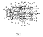
- the braking corrector comprises a body 10 provided with three stepped bores 12,14,16.
- a casing 11 is fixedly mounted on the body 10 and defines with it a chamber 13.
- a piston 18 is slideably mounted and is urged into abutment against a surface of an annular mass 34 under the effect of a spring 20.
- the spring 20 is maintained in position in the bore 12 by a screw 22 which also serves to adjust the calibration of the spring.
- the piston 18 also incorporates an annular seal 24.
- the second bore 14 is provided with a threaded inlet port 26 which is intended to be connected to a source of fluid under pressure (not shown) for example a master cylinder.
- a shaft element 28 is fixedly mounted and incorporates a longitudinal bore 30 connected to a transverse opening 32.
- the annular mass 34 is slideably mounted on the shaft component 28 by way of a ball bearing 36.
- the mass 34 is normally retained in its illustrated rest position against an abutment 37 by a spring 38, which is mounted at one end on the shaft 28 by an adjustable screw 40, and also under the effect of the piston 24.
- the third bore 16 comprises a threaded outlet port 42 intended to be connected to the brakes of the rear wheels of the vehicle (not shown).
- a valve seat 44 is mounted having a longitudinal bore 46 connecting the bore 16 to the chamber 13.
- the valve seat 44 includes an annular seal 48 which cooperates, when the mass 34 comes to bear against the valve seat, with the mass and closes the passage between the inlet port 26 and the rear brakes of the vehicle.
- the corrector is mounted in a vehicle in such a way that the longitudinal axis A of the corrector is parrallel to that of the vehicle, the casing facing towards the rear.
- the corrector described above operates as follows : During a first phase of braking, as long as the combination of the deceleration and the pressure in the chamber 1 3 remains less than the predetermined threshold, the mass 34 remains at rest against the abutment 37 under the effect of the piston 18. Hydraulic fluid passes from the master cylinder through the bores 14, 30, the opening 32, and the bores 46, 16 towards the brakes of the vehicle. The hydraulic pressure in the chamber 13 rises and acts upon the surface of the piston 18. When the pressure exceeds a predetermined threshold the piston 18 moves to the right, looking at the drawing, under the influence of the pressure differential to which it is subject.
- the mass then moves to the right, looking at the Figure, and closes the valve 44.
- the hydraulic pressure in the brakes of the rear wheels remains constant after the closure of the valve 44 and the risk of the rear wheels skidding is thus reduced to a minimum.
- transverse opening 32 is situated inside the annular mass 34 ensures free movement of the mass once the threshold is exceeded.
- the flow of fluid is also distributed over the mass so that the risk of eddies and turbulence, which could undesirably impede or assist the movement of the mass 34, is reduced to a minimum.
- the spring 20 is very considerably stronger than the return spring 38, typically of the order of 10 to 20 times stronger.
- a device according to the invention is particularly suitable for high speed vehicles provided with powerful braking systems which in use are thus subject to high braking decelerations.
- Adjustement of the closing pressure of the corrector is carried out as follows : the casing 11 is first removed from the body 10 and the piston 18 is maintained in its closed position in the bore 12. The corrector is then placed in an inclined position so that the force to which the mass 34 is subjected is equivalent to the deceleration force of the required threshold.
- the outlet port 42 is connected to a source of vacuum and the screw 40 is adjusted so as to obtain closure of the valve 42.
- the response time may be undesirably long.
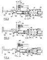
- the second embodiment of the invention includes modifications which shorten the response time.
- a braking corrector similar to that of Figure 1 comprises a piston 118 urged to the left (when viewing the drawings) by two springs 120-121 which are respectively and independently adjustable by two screws 122-123.
- the piston 118 At its end remote from the spring 120-121, the piston 118 has a portion of reduced cross- section 125 which terminates in a head 127.
- the piston 118 also has an abutment surface 128 adjacent the portion 125.
- the mass 134 has an internal circumferential groove 129, limited at an end adjacent the piston 118 by an abutment surface 130.
- the piston 118 also includes a longitudinally extending slot 131 in which is slideably received a pin 132 which is urged to the left by spring 121.
Landscapes
- Engineering & Computer Science (AREA)
- Transportation (AREA)
- Mechanical Engineering (AREA)
- Hydraulic Control Valves For Brake Systems (AREA)
- Regulating Braking Force (AREA)
Applications Claiming Priority (4)
| Application Number | Priority Date | Filing Date | Title |
|---|---|---|---|
| FR8417728A FR2573376B1 (fr) | 1984-11-21 | 1984-11-21 | Correcteur de freinage asservi a la deceleration |
| FR8417728 | 1984-11-21 | ||
| FR8509369A FR2583691B2 (fr) | 1985-06-20 | 1985-06-20 | Correcteur de freinage asservi a la deceleration |
| FR8509369 | 1985-06-20 |
Publications (2)
| Publication Number | Publication Date |
|---|---|
| EP0184955A1 true EP0184955A1 (fr) | 1986-06-18 |
| EP0184955B1 EP0184955B1 (fr) | 1989-01-18 |
Family
ID=26224244
Family Applications (1)
| Application Number | Title | Priority Date | Filing Date |
|---|---|---|---|
| EP85402194A Expired EP0184955B1 (fr) | 1984-11-21 | 1985-11-13 | Correcteur de freinage asservi à la décélération |
Country Status (7)
| Country | Link |
|---|---|
| US (1) | US4673223A (fr) |
| EP (1) | EP0184955B1 (fr) |
| JP (1) | JPH0645335B2 (fr) |
| KR (1) | KR930005954B1 (fr) |
| AU (1) | AU576026B2 (fr) |
| DE (1) | DE3567608D1 (fr) |
| ES (1) | ES8609074A1 (fr) |
Cited By (1)
| Publication number | Priority date | Publication date | Assignee | Title |
|---|---|---|---|---|
| EP0210880B1 (fr) * | 1985-06-20 | 1989-01-04 | BENDIX France | Correcteur de freinage asservi à la décélération |
Families Citing this family (2)
| Publication number | Priority date | Publication date | Assignee | Title |
|---|---|---|---|---|
| US4595243A (en) * | 1984-09-10 | 1986-06-17 | Allied Corporation | Deceleration and pressure sensitive proportioning valve |
| FR2660269B1 (fr) * | 1990-03-29 | 1992-06-12 | Bendix Europ Services Tech | Compensateur de freinage a valve additionnelle. |
Citations (13)
| Publication number | Priority date | Publication date | Assignee | Title |
|---|---|---|---|---|
| US3489465A (en) * | 1966-08-22 | 1970-01-13 | Wagner Electric Corp | Control valve |
| US3773362A (en) * | 1971-12-01 | 1973-11-20 | Bendix Corp | Proportioning valve with pressure limiting |
| US3795424A (en) * | 1971-08-16 | 1974-03-05 | Bendix Corp | Deceleration responsive proportioning valve for vehicle braking system |
| DE2736052A1 (de) * | 1976-11-16 | 1978-05-18 | Toyota Motor Co Ltd | Hydraulikbremsdrucksteuergeraet fuer fahrzeuge |
| DE2800822A1 (de) * | 1977-01-12 | 1978-07-13 | Toyota Motor Co Ltd | Traegheitsgesteuertes ventil fuer ein fahrzeugbremssystem |
| GB2041127A (en) * | 1979-01-12 | 1980-09-03 | Akebono Brake Ind | Hydraulic pressure control valve assembly for dual circuit braking systems |
| EP0019509A1 (fr) * | 1979-05-09 | 1980-11-26 | Societe Anonyme D.B.A. | Correcteur de freinage asservi à la décélération |
| FR2468491A1 (fr) * | 1979-10-30 | 1981-05-08 | Dba | Correcteur de freinage asservi a la deceleration |
| GB2097080A (en) * | 1981-04-04 | 1982-10-27 | Lucas Industries Ltd | Deceleration-sensing pressure proportioning or limiting valve assembly for vehicle braking systems |
| DE3138957A1 (de) * | 1981-09-30 | 1983-04-14 | Alfred Teves Gmbh, 6000 Frankfurt | Bremsdrucksteuereinheit fuer eine hydraulische oder pneumatische kraftfahrzeugbremsanlage |
| DE3238132A1 (de) * | 1982-10-14 | 1984-04-19 | Lucas Industries P.L.C., Birmingham, West Midlands | Bremskraftregler fuer eine hydraulische fahrzeugbremsanlage |
| EP0109893A1 (fr) * | 1982-11-23 | 1984-05-30 | BENDIX France | Correcteur de freinage double circuit asservi à la décélération |
| GB2130323A (en) * | 1982-11-18 | 1984-05-31 | Teves Gmbh Alfred | Vehicle deceleration responsive braking pressure control device |
Family Cites Families (12)
| Publication number | Priority date | Publication date | Assignee | Title |
|---|---|---|---|---|
| US3476443A (en) * | 1968-08-02 | 1969-11-04 | Gen Motors Corp | Inertia sensing proportioner |
| US3881786A (en) * | 1971-03-15 | 1975-05-06 | Kelsey Hayes Co | Inertia responsive proportioning valve |
| GB1408202A (en) * | 1971-09-23 | 1975-10-01 | Nissan Motor | Fluid pressure regulating device for automotive braking systems |
| JPS5221661B2 (fr) * | 1972-08-12 | 1977-06-11 | ||
| US3888546A (en) * | 1973-11-14 | 1975-06-10 | Gen Motors Corp | Proportioning valve system for rear braking circuit |
| US3950037A (en) * | 1974-05-30 | 1976-04-13 | Ford Motor Company | Brake proportioning valve for a motor vehicle responsive to both the rate of vehicle deceleration and vehicle load variation |
| JPS5285681A (en) * | 1976-01-08 | 1977-07-16 | Nissan Motor Co Ltd | Brake pressure control device |
| JPS534168A (en) * | 1976-07-01 | 1978-01-14 | Jidosha Kiki Co Ltd | Brake fluid pressure control equipment |
| FR2437962A1 (fr) * | 1978-10-05 | 1980-04-30 | Dba | Compensateur de freinage asservi a la deceleration |
| FR2502087A1 (fr) * | 1981-03-18 | 1982-09-24 | Dba | Correcteur de freinage pour vehicule automobile asservi a la deceleration |
| FR2513954B1 (fr) * | 1981-10-06 | 1987-06-26 | Dba | Correcteur de freinage asservi a la deceleration |
| US4515810A (en) * | 1983-10-06 | 1985-05-07 | American Cyanamid Company | Composition of matter |
-
1985
- 1985-11-13 DE DE8585402194T patent/DE3567608D1/de not_active Expired
- 1985-11-13 EP EP85402194A patent/EP0184955B1/fr not_active Expired
- 1985-11-18 AU AU50011/85A patent/AU576026B2/en not_active Ceased
- 1985-11-20 US US06/800,173 patent/US4673223A/en not_active Expired - Fee Related
- 1985-11-20 KR KR1019850008673A patent/KR930005954B1/ko not_active Expired - Fee Related
- 1985-11-21 ES ES549149A patent/ES8609074A1/es not_active Expired
- 1985-11-21 JP JP60259930A patent/JPH0645335B2/ja not_active Expired - Lifetime
Patent Citations (13)
| Publication number | Priority date | Publication date | Assignee | Title |
|---|---|---|---|---|
| US3489465A (en) * | 1966-08-22 | 1970-01-13 | Wagner Electric Corp | Control valve |
| US3795424A (en) * | 1971-08-16 | 1974-03-05 | Bendix Corp | Deceleration responsive proportioning valve for vehicle braking system |
| US3773362A (en) * | 1971-12-01 | 1973-11-20 | Bendix Corp | Proportioning valve with pressure limiting |
| DE2736052A1 (de) * | 1976-11-16 | 1978-05-18 | Toyota Motor Co Ltd | Hydraulikbremsdrucksteuergeraet fuer fahrzeuge |
| DE2800822A1 (de) * | 1977-01-12 | 1978-07-13 | Toyota Motor Co Ltd | Traegheitsgesteuertes ventil fuer ein fahrzeugbremssystem |
| GB2041127A (en) * | 1979-01-12 | 1980-09-03 | Akebono Brake Ind | Hydraulic pressure control valve assembly for dual circuit braking systems |
| EP0019509A1 (fr) * | 1979-05-09 | 1980-11-26 | Societe Anonyme D.B.A. | Correcteur de freinage asservi à la décélération |
| FR2468491A1 (fr) * | 1979-10-30 | 1981-05-08 | Dba | Correcteur de freinage asservi a la deceleration |
| GB2097080A (en) * | 1981-04-04 | 1982-10-27 | Lucas Industries Ltd | Deceleration-sensing pressure proportioning or limiting valve assembly for vehicle braking systems |
| DE3138957A1 (de) * | 1981-09-30 | 1983-04-14 | Alfred Teves Gmbh, 6000 Frankfurt | Bremsdrucksteuereinheit fuer eine hydraulische oder pneumatische kraftfahrzeugbremsanlage |
| DE3238132A1 (de) * | 1982-10-14 | 1984-04-19 | Lucas Industries P.L.C., Birmingham, West Midlands | Bremskraftregler fuer eine hydraulische fahrzeugbremsanlage |
| GB2130323A (en) * | 1982-11-18 | 1984-05-31 | Teves Gmbh Alfred | Vehicle deceleration responsive braking pressure control device |
| EP0109893A1 (fr) * | 1982-11-23 | 1984-05-30 | BENDIX France | Correcteur de freinage double circuit asservi à la décélération |
Cited By (1)
| Publication number | Priority date | Publication date | Assignee | Title |
|---|---|---|---|---|
| EP0210880B1 (fr) * | 1985-06-20 | 1989-01-04 | BENDIX France | Correcteur de freinage asservi à la décélération |
Also Published As
| Publication number | Publication date |
|---|---|
| AU576026B2 (en) | 1988-08-11 |
| ES549149A0 (es) | 1986-07-16 |
| DE3567608D1 (en) | 1989-02-23 |
| US4673223A (en) | 1987-06-16 |
| KR930005954B1 (ko) | 1993-06-30 |
| JPH0645335B2 (ja) | 1994-06-15 |
| EP0184955B1 (fr) | 1989-01-18 |
| ES8609074A1 (es) | 1986-07-16 |
| JPS61135851A (ja) | 1986-06-23 |
| AU5001185A (en) | 1986-05-29 |
| KR860003943A (ko) | 1986-06-16 |
Similar Documents
| Publication | Publication Date | Title |
|---|---|---|
| JPH0134814B2 (fr) | ||
| US3512844A (en) | Skid control system including hydraulic modulating and proportioning valve | |
| US3480336A (en) | Hydraulic actuated skid control device | |
| EP0184955A1 (fr) | Correcteur de freinage asservi à la décélération | |
| US4116493A (en) | Brake pressure control valve | |
| GB2032550A (en) | Inertia sensing brake proportioning valve for a vehicle | |
| JPS6344585B2 (fr) | ||
| CA1092481A (fr) | Modulateur de freinage agissant en fonction de la charge, avec temporisation | |
| US3969001A (en) | Control mechanism for automotive vehicle hydraulic braking system | |
| EP0340215B1 (fr) | Soupape sensible a la deceleration, a la pression et au couple de freinage | |
| US4560208A (en) | Brake pressure control unit of deceleration-responsive type | |
| EP0310036B1 (fr) | Valve proportionnelle pour dispositif antipatinage | |
| EP0096346B1 (fr) | Valve de commande hydraulique pour la pression de freinage du type dépendant de la décélération pour véhicules automobiles | |
| US4260196A (en) | Brake pressure control valve with double split point | |
| US4036535A (en) | Braking fluid pressure control device | |
| US4351570A (en) | Vehicle brake pressure proportioning valves | |
| GB2065806A (en) | Vehicle Brake Pressure Proportioning Valves | |
| GB1587395A (en) | Braking correction device | |
| US4712840A (en) | Deceleration-responsive braking corrector | |
| CA1319897C (fr) | Soupape de remplissage rapide incorporee au cylindre principal d'un systeme de freinage | |
| GB2127506A (en) | Deceleration sensitive brake control valve | |
| KR100261430B1 (ko) | 자동차의 프로포셔닝 밸브 | |
| US4279447A (en) | Brake oil pressure controlling valve device for vehicle use | |
| EP0325390A1 (fr) | Systèmes d'antiblocage pour véhicules | |
| EP0096259A2 (fr) | Valve de commande à fluide sous pression du type dépendant de la décélération |
Legal Events
| Date | Code | Title | Description |
|---|---|---|---|
| PUAI | Public reference made under article 153(3) epc to a published international application that has entered the european phase |
Free format text: ORIGINAL CODE: 0009012 |
|
| 17P | Request for examination filed |
Effective date: 19851115 |
|
| AK | Designated contracting states |
Kind code of ref document: A1 Designated state(s): DE GB IT |
|
| 17Q | First examination report despatched |
Effective date: 19871208 |
|
| GRAA | (expected) grant |
Free format text: ORIGINAL CODE: 0009210 |
|
| AK | Designated contracting states |
Kind code of ref document: B1 Designated state(s): DE GB IT |
|
| REF | Corresponds to: |
Ref document number: 3567608 Country of ref document: DE Date of ref document: 19890223 |
|
| ITF | It: translation for a ep patent filed | ||
| PLBE | No opposition filed within time limit |
Free format text: ORIGINAL CODE: 0009261 |
|
| STAA | Information on the status of an ep patent application or granted ep patent |
Free format text: STATUS: NO OPPOSITION FILED WITHIN TIME LIMIT |
|
| 26N | No opposition filed | ||
| ITTA | It: last paid annual fee | ||
| PGFP | Annual fee paid to national office [announced via postgrant information from national office to epo] |
Ref country code: GB Payment date: 19961104 Year of fee payment: 12 |
|
| PGFP | Annual fee paid to national office [announced via postgrant information from national office to epo] |
Ref country code: DE Payment date: 19961122 Year of fee payment: 12 |
|
| PG25 | Lapsed in a contracting state [announced via postgrant information from national office to epo] |
Ref country code: GB Free format text: LAPSE BECAUSE OF NON-PAYMENT OF DUE FEES Effective date: 19971113 |
|
| GBPC | Gb: european patent ceased through non-payment of renewal fee |
Effective date: 19971113 |
|
| PG25 | Lapsed in a contracting state [announced via postgrant information from national office to epo] |
Ref country code: DE Free format text: LAPSE BECAUSE OF NON-PAYMENT OF DUE FEES Effective date: 19980801 |