EP0184973A2 - Stützsystem für Steigrohrleitung - Google Patents
Stützsystem für Steigrohrleitung Download PDFInfo
- Publication number
- EP0184973A2 EP0184973A2 EP85630216A EP85630216A EP0184973A2 EP 0184973 A2 EP0184973 A2 EP 0184973A2 EP 85630216 A EP85630216 A EP 85630216A EP 85630216 A EP85630216 A EP 85630216A EP 0184973 A2 EP0184973 A2 EP 0184973A2
- Authority
- EP
- European Patent Office
- Prior art keywords
- termination
- passage
- sleeve
- termination head
- forward end
- Prior art date
- Legal status (The legal status is an assumption and is not a legal conclusion. Google has not performed a legal analysis and makes no representation as to the accuracy of the status listed.)
- Granted
Links
Images


Classifications
-
- F—MECHANICAL ENGINEERING; LIGHTING; HEATING; WEAPONS; BLASTING
- F16—ENGINEERING ELEMENTS AND UNITS; GENERAL MEASURES FOR PRODUCING AND MAINTAINING EFFECTIVE FUNCTIONING OF MACHINES OR INSTALLATIONS; THERMAL INSULATION IN GENERAL
- F16L—PIPES; JOINTS OR FITTINGS FOR PIPES; SUPPORTS FOR PIPES, CABLES OR PROTECTIVE TUBING; MEANS FOR THERMAL INSULATION IN GENERAL
- F16L37/00—Couplings of the quick-acting type
- F16L37/002—Couplings of the quick-acting type which can be controlled at a distance
-
- E—FIXED CONSTRUCTIONS
- E21—EARTH OR ROCK DRILLING; MINING
- E21B—EARTH OR ROCK DRILLING; OBTAINING OIL, GAS, WATER, SOLUBLE OR MELTABLE MATERIALS OR A SLURRY OF MINERALS FROM WELLS
- E21B17/00—Drilling rods or pipes; Flexible drill strings; Kellies; Drill collars; Sucker rods; Cables; Casings; Tubings
- E21B17/01—Risers
-
- E—FIXED CONSTRUCTIONS
- E21—EARTH OR ROCK DRILLING; MINING
- E21B—EARTH OR ROCK DRILLING; OBTAINING OIL, GAS, WATER, SOLUBLE OR MELTABLE MATERIALS OR A SLURRY OF MINERALS FROM WELLS
- E21B19/00—Handling rods, casings, tubes or the like outside the borehole, e.g. in the derrick; Apparatus for feeding the rods or cables
- E21B19/002—Handling rods, casings, tubes or the like outside the borehole, e.g. in the derrick; Apparatus for feeding the rods or cables specially adapted for underwater drilling
-
- E—FIXED CONSTRUCTIONS
- E21—EARTH OR ROCK DRILLING; MINING
- E21B—EARTH OR ROCK DRILLING; OBTAINING OIL, GAS, WATER, SOLUBLE OR MELTABLE MATERIALS OR A SLURRY OF MINERALS FROM WELLS
- E21B33/00—Sealing or packing boreholes or wells
- E21B33/02—Surface sealing or packing
- E21B33/03—Well heads; Setting-up thereof
- E21B33/035—Well heads; Setting-up thereof specially adapted for underwater installations
- E21B33/038—Connectors used on well heads, e.g. for connecting blow-out preventer and riser
-
- F—MECHANICAL ENGINEERING; LIGHTING; HEATING; WEAPONS; BLASTING
- F16—ENGINEERING ELEMENTS AND UNITS; GENERAL MEASURES FOR PRODUCING AND MAINTAINING EFFECTIVE FUNCTIONING OF MACHINES OR INSTALLATIONS; THERMAL INSULATION IN GENERAL
- F16L—PIPES; JOINTS OR FITTINGS FOR PIPES; SUPPORTS FOR PIPES, CABLES OR PROTECTIVE TUBING; MEANS FOR THERMAL INSULATION IN GENERAL
- F16L39/00—Joints or fittings for double-walled or multi-channel pipes or pipe assemblies
-
- Y—GENERAL TAGGING OF NEW TECHNOLOGICAL DEVELOPMENTS; GENERAL TAGGING OF CROSS-SECTIONAL TECHNOLOGIES SPANNING OVER SEVERAL SECTIONS OF THE IPC; TECHNICAL SUBJECTS COVERED BY FORMER USPC CROSS-REFERENCE ART COLLECTIONS [XRACs] AND DIGESTS
- Y10—TECHNICAL SUBJECTS COVERED BY FORMER USPC
- Y10S—TECHNICAL SUBJECTS COVERED BY FORMER USPC CROSS-REFERENCE ART COLLECTIONS [XRACs] AND DIGESTS
- Y10S285/00—Pipe joints or couplings
- Y10S285/92—Remotely controlled
Definitions
- This invention relates in general to equipment for drilling and producing subsea wells, and particularly to a seal assembly located at the top of a riser string extending between the subsea well and a floating, drilling or production platform.
- a single stab union is shown for an offshore drilling or production platform.
- a termination head is adapted to be received within a termination housing.
- the termination housing has a number of radial ports that register with passages located in the termination head. These ports contain high pressure fluid for transmission between the vessel and a subsea well. If it is necessary to temporarily disconnect the lower end of the riser from the subsea well, the termination head can be pulled upward from the termination housing. The lines or hoses connected to the termination housing can remain in place, connected to the housing.
- Seals are required to seal the junction of the termination housing radial ports with the termination head radial passages.
- static elastomeric seals are shown encircling each outlet of the termination head ports.
- a movable seal is provided for sealing the radial passages between the termination head and termination housing.
- the seal assembly includes a sliding sleeve carried in the radial passage of the termination housing.
- the sleeve has a passage therethrough for transmitting fluid.
- the sleeve has a forward end which is dimensioned for sealing reception inside the radial passage of the termination head.
- the sleeve also has an annular flange located in a chamber within the termination housing passage.
- the flange serves as a piston.
- the hydraulic fluid directed to the chamber on opposite sides of the piston retract and advance the sleeve into engagement with the termination head.
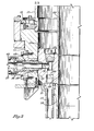
- termination housing 11 is a generally cylindrical member, having an inner cylindrical cavity 13.
- the axis of the termination housing 11 and cavity 13 is normally vertical.
- termination housing 11 may be rigidly secured to a floating vessel (not shown) by means of a latch 15 which engages a diverter housing 17.
- Latch 15 is shown in an open position in Fig. 1 and a closed position in Fig. 2.
- termination housing 11 will be suspended below the diverter housing 17 on cables (not shown) to accommodate wave movement of the vessel.
- An annular shoulder 19 is located at the lower end of cavity 13 and faces upwardly.
- a termination head 21 is adapted to slide downwardly into the inner cavity 13 and locate on the shoulder 19.
- a latch (not shown) will latch the termination head 21 in place.
- Termination head 21 has an axial bore 22.
- a tubular member 23 engages the termination head 21. Member 23 cooperates with other equipment (not shown) to lower and raise the termination head 21 with respect to the termination housing 11.
- a riser adapter joint 25 is secured to the lower end of the termination head 21 and extends downwardly to a string of risers (not shown) that extends to the subsea well (not shown).
- a plurality of flow lines 27 (only one shown) are mounted concentrically around the riser adapter joint 25 and the riser string. The flow lines 27 can deliver fluids to and receive fluids from the subsea well for control and production purposes.
- the flow lines 27 each connect with a longitudinal passage 29 (only one shown) that extends upwardly within the termination head 21.
- Each longitudinal passage 29 intersects a radial passage 31 that extends through the cylindrical surface of the termination head.
- a counterbore 31a is located at the outer surface or entrance of the radial passage 31.
- Two elastomeric seals 32 are shown located within the counterbore 31a.
- the termination housing 11 has a radial passage 33 for each termination head radial passage 31.
- the radial passages 33 (only one shown) are co-axial with the radial passages 31.
- Each housing radial passage 33 contains a fixed cylinder 35, which is bolted to the termination housing 11 and may be considered a part of housing 11.
- a hose adapter 37 is connected to the outer side of each cylinder 35.
- Each hose adapter 37 is connected to a hose (not shown) , which extends to the floating vessel for transmitting fluids.
- the cylinder 35 has a passage therethrough with an outer or rearward end 39a and a forward end 39b.
- the forward end 39b has a greater diameter than the rearward end 39a.
- a stationary sleeve 41 is located near the forward end of the cylinder 35.
- Stationary sleeve 41 has an inner diameter that is the same as the inner diameter of the passage forward end 39a.
- Stationary sleeve 41 is spaced inwardly from the passage rearward end 39a a selected distance, to define a chamber for receiving hydraulic fluid.
- Passage portions 39a and 39b are coaxial with the termination head 11 passage 33.
- a sliding sleeve 43 is reciprocally carried within the passage portions 39a and 39b .
- the sliding sleeve 43 has a forward or sealing end 43a that is of a lesser diameter than the inner diameters of the stationary sleeve 41 and passage portion 39a.
- the sealing end 43a is -adapted to fit tightly and sealingly within the counterbore 31a of the termination head radial passage 31.
- seals 32 are shown in counterbore 31a, they could also be located on sealing end 43a. This would allow replacement of the seals 32 by removing the sliding sleeve 43.
- Sliding sleeve 43 has a bore 45 therethrough (Fig. 1) for the transmission of fluids between the radial passage 31 and the bore of the hose adapter 37. Bore 45 is coaxial with radial passages 31 and 33.
- a flange 47 encircles the sliding sleeve 43 at a point between its ends. Flange 47 has a seal 49 and is closely received within the passage portion 39b between the stationary sleeve 41 and the passage portion 39a. Flange 47 serves as a piston for advancing and retracting the sliding sleeve 43.
- a hydraulic passage 51 extends from a source of hydraulic fluid (not shown) to the passage portion 39b on the outer or rearward side of flange 47.
- a hydraulic passage 53 also extends from a source of hydraulic fluid to the passage portion 39b , but on the forward side of flange 47.
- the termination housing 11 will be supported from the floating vessel (not shown) as described in U.S. Patent No. 4 403 658.
- the sliding sleeves 43 will be retracted as shown in Fig. 1 prior to lowering of the termination head 21 into the termination housing 11.
- the passages 31 in the termination head 21 will align with the sliding sleeves 43 in the termination housing 11.
- Hydraulic fluid pressure is applied through passage 51 to cause the sliding sleeve 43 to extend into the counterbore 31a.
- Passage 53 will serve as a return for the hydraulic fluid. Passages 51 and 53 are isolated from any fluid contained within the cylinder passage 39a.
- fluid pressure may be applied through the hose adapter 37 and into the passage portion 39a.
- the fluid flows through the bore 45 (Fig. 1) and into the passages 31 and 29 in the termination head.
- the fluid is used at the subsea well for various functions.
- the fluid pressure in the passage portion 39a will act on the rearward end of the sliding sleeve 43.
- the same fluid pressure will act on the forward end of the sliding sleeve 43.
- the rearward edge has a greater cross-sectional thickness than the forward end because of its greater outer diameters.
- This greater cross-sectional thickness results in a larger pressure area on the rearward end of the sliding sleeve 43 than on the forward end of sliding sleeve 43 at sealing end 43a.
- the greater pressure area results in a net inward force, tending to push the sliding sleeve 43 inward, even though hydraulic fluid pressure is removed from the hydraulic passages 51 and 53.
- the sliding sleeve assembly avoids any damage to the seals that might occur while the termination head is being lowered into the termination housing.
- the sliding sleeve utilizes internal pressure within the passage to maintain the seals in engagement, apart from any hydraulic fluid pressure used to reciprocate the sleeve from one position to the other. Loss of pressure or slight movement of the sleeve will not affect the seal.
- the sliding sleeve assembly can be moved slightly by means of its bolted connection to the termination housing to provide for final alignment with the termination head radial passage.
Landscapes
- Engineering & Computer Science (AREA)
- Geology (AREA)
- Life Sciences & Earth Sciences (AREA)
- Mining & Mineral Resources (AREA)
- Mechanical Engineering (AREA)
- General Engineering & Computer Science (AREA)
- Physics & Mathematics (AREA)
- Environmental & Geological Engineering (AREA)
- Fluid Mechanics (AREA)
- General Life Sciences & Earth Sciences (AREA)
- Geochemistry & Mineralogy (AREA)
- Earth Drilling (AREA)
- Internal Circuitry In Semiconductor Integrated Circuit Devices (AREA)
- Laying Of Electric Cables Or Lines Outside (AREA)
Applications Claiming Priority (2)
| Application Number | Priority Date | Filing Date | Title |
|---|---|---|---|
| US06/679,787 US4592426A (en) | 1984-12-10 | 1984-12-10 | Upper termination with sliding sleeve seals |
| US679787 | 1991-04-03 |
Publications (3)
| Publication Number | Publication Date |
|---|---|
| EP0184973A2 true EP0184973A2 (de) | 1986-06-18 |
| EP0184973A3 EP0184973A3 (en) | 1988-07-27 |
| EP0184973B1 EP0184973B1 (de) | 1990-07-18 |
Family
ID=24728365
Family Applications (1)
| Application Number | Title | Priority Date | Filing Date |
|---|---|---|---|
| EP85630216A Expired - Lifetime EP0184973B1 (de) | 1984-12-10 | 1985-12-03 | Stützsystem für Steigrohrleitung |
Country Status (4)
| Country | Link |
|---|---|
| US (1) | US4592426A (de) |
| EP (1) | EP0184973B1 (de) |
| DE (1) | DE3578748D1 (de) |
| NO (1) | NO854897L (de) |
Cited By (1)
| Publication number | Priority date | Publication date | Assignee | Title |
|---|---|---|---|---|
| WO2014035375A1 (en) * | 2012-08-28 | 2014-03-06 | Halliburton Energy Services, Inc. | Riser displacement and cleaning systems and methods of use |
Families Citing this family (15)
| Publication number | Priority date | Publication date | Assignee | Title |
|---|---|---|---|---|
| US4741402A (en) * | 1986-10-14 | 1988-05-03 | Hughes Tool Company | Subsea hydraulic connector with multiple ports |
| US4834825A (en) * | 1987-09-21 | 1989-05-30 | Robert Adams | Assembly for connecting multi-duct conduits |
| USRE34332E (en) * | 1987-09-21 | 1993-08-03 | Assembly for connecting multi-duct conduits | |
| US5727630A (en) * | 1996-08-09 | 1998-03-17 | Abb Vetco Gray Inc. | Telescopic joint control line system |
| US6082460A (en) * | 1997-01-21 | 2000-07-04 | Cooper Cameron Corporation | Apparatus and method for controlling hydraulic control fluid circuitry for a tubing hanger |
| US6805382B2 (en) * | 2002-03-06 | 2004-10-19 | Abb Vetco Gray Inc. | One stroke soft-land flowline connector |
| US20060134051A1 (en) * | 2002-09-26 | 2006-06-22 | Xavier Blin | Glossy non-transfer composition comprising a sequenced polymer |
| US7571772B2 (en) * | 2005-09-19 | 2009-08-11 | Vetco Gray Inc. | System, method, and apparatus for a radially-movable line termination system for a riser string on a drilling rig |
| BR112015005874B1 (pt) | 2012-09-21 | 2017-04-18 | Nat Oilwell Varco Lp | unidade de pescoço de ganso, e, método para acoplar uma coluna de tubos ascendentes a uma sonda de perfuração fora da costa |
| US9759018B2 (en) * | 2014-12-12 | 2017-09-12 | Hydril USA Distribution LLC | System and method of alignment for hydraulic coupling |
| US9528340B2 (en) * | 2014-12-17 | 2016-12-27 | Hydrill USA Distribution LLC | Solenoid valve housings for blowout preventer |
| US10202839B2 (en) * | 2014-12-17 | 2019-02-12 | Hydril USA Distribution LLC | Power and communications hub for interface between control pod, auxiliary subsea systems, and surface controls |
| US10404052B2 (en) * | 2015-05-07 | 2019-09-03 | Hydril Usa Distribution, Llc | Systems and methods for handling overcurrent and undercurrent conditions in subsea control subsystem components |
| US10303819B2 (en) * | 2016-08-25 | 2019-05-28 | Drilling Info, Inc. | Systems and methods for allocating hydrocarbon production values |
| US10273766B1 (en) * | 2018-03-08 | 2019-04-30 | Jle Inovaçao Tecnologica Ltda Epp | Plug and play connection system for a below-tension-ring managed pressure drilling system |
Family Cites Families (7)
| Publication number | Priority date | Publication date | Assignee | Title |
|---|---|---|---|---|
| US2725122A (en) * | 1953-07-29 | 1955-11-29 | Gen Motors Corp | Hydraulic line seal |
| US3326579A (en) * | 1964-05-27 | 1967-06-20 | Rockwell Mfg Co | Multiple conduit connection |
| US3348575A (en) * | 1965-08-16 | 1967-10-24 | Int Harvester Co | Hydraulically actuatable fluid coupling |
| US3874706A (en) * | 1971-10-15 | 1975-04-01 | Hydrotech Int Inc | Fluid actuated pipe connection |
| US3780243A (en) * | 1972-10-12 | 1973-12-18 | P Koomey | Apparatus for making and breaking an electrical underwater connection between releasable underwater members |
| US3966235A (en) * | 1973-04-30 | 1976-06-29 | Hydril Company | Underwater sealing of exposed ports in relatively closable members |
| US4403658A (en) * | 1980-09-04 | 1983-09-13 | Hughes Tool Company | Multiline riser support and connection system and method for subsea wells |
-
1984
- 1984-12-10 US US06/679,787 patent/US4592426A/en not_active Expired - Fee Related
-
1985
- 1985-12-03 DE DE8585630216T patent/DE3578748D1/de not_active Expired - Lifetime
- 1985-12-03 EP EP85630216A patent/EP0184973B1/de not_active Expired - Lifetime
- 1985-12-05 NO NO854897A patent/NO854897L/no unknown
Cited By (2)
| Publication number | Priority date | Publication date | Assignee | Title |
|---|---|---|---|---|
| WO2014035375A1 (en) * | 2012-08-28 | 2014-03-06 | Halliburton Energy Services, Inc. | Riser displacement and cleaning systems and methods of use |
| US9284795B2 (en) | 2012-08-28 | 2016-03-15 | Halliburton Energy Services, Inc. | Riser displacement and cleaning systems and methods of use |
Also Published As
| Publication number | Publication date |
|---|---|
| DE3578748D1 (de) | 1990-08-23 |
| EP0184973B1 (de) | 1990-07-18 |
| EP0184973A3 (en) | 1988-07-27 |
| NO854897L (no) | 1986-06-11 |
| US4592426A (en) | 1986-06-03 |
Similar Documents
| Publication | Publication Date | Title |
|---|---|---|
| EP0184973B1 (de) | Stützsystem für Steigrohrleitung | |
| US3052299A (en) | Underwater wellhead with remotelydetachable flow line | |
| US5727630A (en) | Telescopic joint control line system | |
| US3732923A (en) | Remote underwater flowline connection | |
| CA1335811C (en) | Drill pipes and casings utilizing multi-conduit tubulars | |
| US3090437A (en) | Underwater wellhead flow line connector | |
| GB2362398A (en) | Device for installation and flow test of subsea completions | |
| EP0583121B1 (de) | Selbstausrichtende Kupplung in Winkel- sowie in Radiallage | |
| US4469136A (en) | Subsea flowline connector | |
| US20190186227A1 (en) | Oilfield apparatus and methods of use | |
| US4589689A (en) | Energized seal for upper termination | |
| GB1567130A (en) | Swivel connector | |
| EP3230552B1 (de) | Ausrichtungssystem und -verfahren für eine hydraulische kupplung von hilfsleitungen | |
| US3233666A (en) | Underwater wellhead with remotelydetachable flow line | |
| EP1463870B1 (de) | System und verfahren zur verringerung des aufpralls auf eruptionskreuzen bei bohrlochvorgängen mit eruptionskreuzen | |
| US6978844B2 (en) | Filling and circulating apparatus for subsurface exploration | |
| GB2233365A (en) | Sub-sea wireline grease control system | |
| US6220351B1 (en) | System to lower the depth equipment in hydrocarbons wells | |
| US20230212917A1 (en) | Gooseneck connector system | |
| US3474857A (en) | Wellhead closure apparatus | |
| KR100487722B1 (ko) | 미끄럼식죠인트 | |
| GB2170579A (en) | Retrievable subset T.F.L. diverter switch valve | |
| SU981579A1 (ru) | Устройство дл соединени и разъединени колонны труб с пакером | |
| WO2001053654A1 (en) | Seal protection apparatus | |
| WO1993023654A1 (en) | Top drive apparatus |
Legal Events
| Date | Code | Title | Description |
|---|---|---|---|
| PUAI | Public reference made under article 153(3) epc to a published international application that has entered the european phase |
Free format text: ORIGINAL CODE: 0009012 |
|
| AK | Designated contracting states |
Kind code of ref document: A2 Designated state(s): DE FR GB |
|
| PUAL | Search report despatched |
Free format text: ORIGINAL CODE: 0009013 |
|
| AK | Designated contracting states |
Kind code of ref document: A3 Designated state(s): DE FR GB |
|
| 17P | Request for examination filed |
Effective date: 19881111 |
|
| 17Q | First examination report despatched |
Effective date: 19891018 |
|
| GRAA | (expected) grant |
Free format text: ORIGINAL CODE: 0009210 |
|
| AK | Designated contracting states |
Kind code of ref document: B1 Designated state(s): DE FR GB |
|
| ET | Fr: translation filed | ||
| REF | Corresponds to: |
Ref document number: 3578748 Country of ref document: DE Date of ref document: 19900823 |
|
| PLBE | No opposition filed within time limit |
Free format text: ORIGINAL CODE: 0009261 |
|
| STAA | Information on the status of an ep patent application or granted ep patent |
Free format text: STATUS: NO OPPOSITION FILED WITHIN TIME LIMIT |
|
| 26N | No opposition filed | ||
| PGFP | Annual fee paid to national office [announced via postgrant information from national office to epo] |
Ref country code: DE Payment date: 19921125 Year of fee payment: 8 |
|
| PGFP | Annual fee paid to national office [announced via postgrant information from national office to epo] |
Ref country code: FR Payment date: 19931110 Year of fee payment: 9 |
|
| PGFP | Annual fee paid to national office [announced via postgrant information from national office to epo] |
Ref country code: GB Payment date: 19931116 Year of fee payment: 9 |
|
| PG25 | Lapsed in a contracting state [announced via postgrant information from national office to epo] |
Ref country code: DE Effective date: 19940901 |
|
| PG25 | Lapsed in a contracting state [announced via postgrant information from national office to epo] |
Ref country code: GB Effective date: 19941203 |
|
| GBPC | Gb: european patent ceased through non-payment of renewal fee |
Effective date: 19941203 |
|
| PG25 | Lapsed in a contracting state [announced via postgrant information from national office to epo] |
Ref country code: FR Effective date: 19950831 |
|
| REG | Reference to a national code |
Ref country code: FR Ref legal event code: ST |