EP0184995A2 - Système d'armature empêchant le cissaillement - Google Patents
Système d'armature empêchant le cissaillement Download PDFInfo
- Publication number
- EP0184995A2 EP0184995A2 EP85810587A EP85810587A EP0184995A2 EP 0184995 A2 EP0184995 A2 EP 0184995A2 EP 85810587 A EP85810587 A EP 85810587A EP 85810587 A EP85810587 A EP 85810587A EP 0184995 A2 EP0184995 A2 EP 0184995A2
- Authority
- EP
- European Patent Office
- Prior art keywords
- push
- connecting rods
- bars
- reinforcement
- cross
- Prior art date
- Legal status (The legal status is an assumption and is not a legal conclusion. Google has not performed a legal analysis and makes no representation as to the accuracy of the status listed.)
- Granted
Links
Images

Classifications
-
- E—FIXED CONSTRUCTIONS
- E04—BUILDING
- E04C—STRUCTURAL ELEMENTS; BUILDING MATERIALS
- E04C5/00—Reinforcing elements, e.g. for concrete; Auxiliary elements therefor
- E04C5/01—Reinforcing elements of metal, e.g. with non-structural coatings
- E04C5/06—Reinforcing elements of metal, e.g. with non-structural coatings of high bending resistance, i.e. of essentially three-dimensional [3D] extent, e.g. lattice girders
- E04C5/0645—Shear reinforcements, e.g. shearheads for floor slabs
-
- E—FIXED CONSTRUCTIONS
- E04—BUILDING
- E04B—GENERAL BUILDING CONSTRUCTIONS; WALLS, e.g. PARTITIONS; ROOFS; FLOORS; CEILINGS; INSULATION OR OTHER PROTECTION OF BUILDINGS
- E04B5/00—Floors; Floor construction with regard to insulation; Connections specially adapted therefor
- E04B5/43—Floor structures of extraordinary design; Features relating to the elastic stability; Floor structures specially designed for resting on columns only, e.g. mushroom floors
Definitions
- the invention relates to a shear reinforcement system to ensure the load-bearing capacity of zones of reinforced concrete plates that are subject to shear forces, in particular zones of flat slabs that are at risk of punching, each with a lower and upper reinforcement included therein, running parallel to the flat slab and comprising at least one reinforcement layer.
- a common example of such a reinforced concrete slab is the flat ceiling above an extensive underground parking space for commercial vehicles, on which there is a parking lot, and which rests all around on walls, but between them on a support or the majority thereof.
- a shear load acts on the ceiling, but a much larger one on the much smaller circumference of a column.
- an upward transverse force acts on the ceiling, but immediately outside this area there is a downward force of the same amount from the weight of the ceiling and its load, i.e. along the circumference of the column, the ceiling is severely sheared and in the surrounding zone Bend claims what is known to be a very unfavorable type of stress in concrete. This creates the danger that the ceiling will be punched through there.
- zones of reinforced concrete slabs e.g. Flat ceilings
- an extremely complex and dense steel reinforcement e.g. consisting of lower and upper reinforcement layers crossing one another in the longitudinal and transverse directions, connected by countless individual so-called push bars, the placement and fastening of which is extremely critical, and when assembling you usually have to do spacing -Devices to help and you can at least partially the reinforcement bars just insert lengthways.
- Some embodiments of the new push reinforcement system have the common feature that the connecting rods directly above and / or under the webs of the push bar in a mutual distance parallel to each other, which is smaller than the push bar width, and that the push bars are perpendicular to the connecting rods and along these, at least insofar as it is not the outer on both sides, so alternately laterally offset that they are at least two each Cross connecting rods and, thanks to the arrangement and firm connection at the intersection points, bring about a firm connection of all connecting rods with one another, so that the drawer element as a whole forms a coherent whole.
- the push bars in the direction of the connecting rods are at least approximately evenly spaced in rows and they are laterally offset along one of the connecting rods in such a way that they alternate between this and the adjacent connecting rod on the left, this and the adjacent connecting rod on the right, and the two left and right adjacent connecting rods, but then do not cross the relevant connecting rod itself and are firmly connected to it.
- At least some of the connecting rods can be interrupted where push bars cross the two connecting rods on the left and right, but not the connecting rod in question.
- the other of these variants maintains the uniformity of the structure when assembling two or more push cage elements in that push bars of full width are alternately provided at least along one outer connecting bar, which push bars cross the outer and the next inner connecting bar and are firmly connected thereto, and push bars of less , eg half width, which only cross the outer connecting rod and are firmly connected to it.
- Another embodiment with the aforementioned common feature is designed so that the distance from push bar to push bar in the direction of the connecting rods is alternately equal to a constant value and zero, and that in the latter case the two adjoining push bars 33 forming a pair of push bars are laterally offset from each other that one leg of one is in the middle between the legs of the other. In this case, equal distances between the push arm legs in the longitudinal direction and in the transverse direction are made possible, which will be discussed in more detail below.
- longitudinal connecting rods and cross connecting rods are provided as connecting rods, each of which runs parallel to one another at a distance from rod to rod approximately equal to twice the push bar width, cross each other at right angles and at their crossing points are firmly connected to each other, and that push bars are arranged transversely to each longitudinal connecting rod, which they cross in the middle of their web, where they are firmly connected to it. It is then expedient to arrange the push bars on the longitudinal connecting rods approximately in the middle between the transverse connecting rods. So this is a very regular arrangement: the individual push bars are aligned with each other in the longitudinal and transverse directions. They do not have to connect connecting rods, but the cross-connecting rods serve this purpose separately,
- a variant of this is that longitudinal and transverse connecting rods are provided as connecting rods, each of which is at a distance from rod to rod equal to the push bar width, cross each other at right angles and is firmly connected to one another at their crossing points, and that the push bar is transverse stand on two adjacent longitudinal connecting rods and cross them at the lower end of their legs, where they are firmly connected to them.
- the smaller distances between the connecting rods compared to the previous one, as well as the additional connection of two rods by the push bar naturally lead to greater stability of the entire push basket element;
- the first step here is to attach the push bars as regularly as in the previous arrangement, i.e. such that they are aligned with each other in the longitudinal and transverse directions, and the thrust arm legs can also be given equal distances in both directions.
- a connection at the crossing points can be e.g. Manufacture by using a pipe fitting consisting of three mutually perpendicular pieces of pipe and inserting the longitudinal and transverse connecting rod as well as the push bracket leg in order to glue them, e.g. with an epoxy resin with hardener or with a cyanoacrylate.
- the push bars laterally offset, so that they alternately connect this along a longitudinal connecting rod with the one on the left and the one on the right.
- the cross-connecting rods can also be omitted.
- the push bars are hook-like bent by at least approximately 180 ° in such a way that bars of the upper reinforcement can be inserted into the hook-like bends, and that the push bars are aligned for the same purpose so that the hook-like bends are aligned with one another in rows.
- the legs of the push bars can each have the same distances from one another in the longitudinal direction and in the transverse direction.
- the arm leg density is then isotropic. This is advantageous if the transverse force is approximately the same in both directions or approximately constant around the support. Another advantage is that with large transverse forces you can choose correspondingly small stirrup leg distances without necessarily having to accept smaller ones in one direction, which results in a corresponding saving in material.
- the other embodiments with a fundamentally anisotropic stirrup leg density are in place when transverse forces of different magnitudes are specified in the longitudinal and transverse directions; of course such drawer elements must then be correctly arranged on the construction site - not rotated by 90 °, i.e. then they are not easily foolproof.
- the connecting rods or the longitudinal connecting rods and / or the transverse connecting rods have a smaller mutual distance in the area of the edges of the drawer element than in the middle, and / or that transverse connecting rods are only provided in the relevant edge areas in addition to the longitudinal connecting rods .
- the described embodiments suggest others to those skilled in the art, including those where the drawer element is not, as is most often used, rectangular or in plan is square, but has such a shape that it can be inscribed in a parallelogram, circle or circle sector.
- the connecting rods can run parallel to two mutually opposite parallelogram sides or be arranged radially.
- the material from which the drawer element is made is worth mentioning, because it plays a crucial role in the strength and durability of a building in places of high stress.
- the durability is not a decisive factor or, in the opinion of the owner, besides irrelevant of the costs, the drawer element can consist of ordinary reinforcing steel in the way that has long been common for reinforcement parts.
- the drawer element be made of smooth or at least partially profiled round steel, which is coated with a corrosion-resistant and diffusion-tight plastic, or of stainless steel.
- a corrosion-resistant and diffusion-tight plastic or of stainless steel.
- the suitability of the latter is beyond question and the higher costs are disproportionate to the damage it prevents.
- Certain acids, to a certain extent, are attacked by certain acids if they are very dilute and therefore have a high degree of dissociation, but this is only manifested by a surface discoloration, which is not accompanied by a noticeable increase in volume.
- Cocosamine after curing, this is sufficiently elastic even without a plasticizer, so that it does not form any cracks as a coating, and is perfectly diffusion-tight even against the smallest molecules, and it is also one of the few plastics that are permanently resistant to those pollutants. However, this does not exclude that other plastics with properties suitable for the present purpose are found.
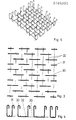
- FIG. 1 shows on a support 1, which is indicated with a bold square, a section of a flat slab 2, while the new shear reinforcement system in it hinted at with four composite drawer elements 3 or a correspondingly larger, and with longitudinally extending lower and upper reinforcement layers 4, 4 'and transverse and lower and upper reinforcement layers 5, 5 ".
- FIG. 1 is viewed as a view from above
- FIG. 2 is the section through the support 1 of the same arrangement seen from the lower edge of the sheet
- the representation of the drawer element 3 in FIG. 2 could only correspond to a specific embodiment - the one from FIGS. 9 to 11 was chosen - but is not to be understood in particular why here also all parts of the drawer element, generally meant according to the invention, are denoted uniformly by 3.
- a first embodiment of the drawer element is shown in Figures 3 to 5; in Figure 3 in top view, in Figure 4 in side view from the direction in Figure 3 below, in Figure 5 for illustration in perspective.
- the mutual distance from connecting rods 32 is smaller than the width of push bars 30, each of which is firmly connected to the two connecting bars 32 crossing it, while narrower push bars 31 at the edge ensure a more uniform finish.
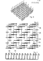
- the mutual spacing of connecting rods 35 is smaller than the width of push bars 33 crossing them, each of which crosses two connecting rods and is firmly connected thereto; the mutual distance of the push bars 33 in the direction of the connecting rods 35 is, however, alternately equal to a constant value and equal to zero, while the legs of the push bars in this direction and transversely to them have the same distances.
- narrower push brackets 34 ensure a uniform closure and the connecting rods 35 are provided at a smaller distance and cross-connecting rods 36 for stiffening the push basket element.
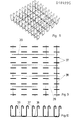
- FIG. 9 to 11 represent a third embodiment of the drawer element, in which push brackets 37 are fastened on longitudinal connecting rods 38 crossing them, which in turn are connected and held together by cross-connecting rods 39.
- the distances between the push handle legs can be kept the same lengthways and crossways.
Landscapes
- Engineering & Computer Science (AREA)
- Architecture (AREA)
- Civil Engineering (AREA)
- Structural Engineering (AREA)
- Physics & Mathematics (AREA)
- Electromagnetism (AREA)
- Reinforcement Elements For Buildings (AREA)
- Manufacture Of Alloys Or Alloy Compounds (AREA)
- Wire Processing (AREA)
- Roof Covering Using Slabs Or Stiff Sheets (AREA)
Priority Applications (1)
| Application Number | Priority Date | Filing Date | Title |
|---|---|---|---|
| AT85810587T ATE65817T1 (de) | 1984-12-12 | 1985-12-11 | Schubbewehrungssystem. |
Applications Claiming Priority (2)
| Application Number | Priority Date | Filing Date | Title |
|---|---|---|---|
| CH591084 | 1984-12-12 | ||
| CH5910/84 | 1984-12-12 |
Publications (3)
| Publication Number | Publication Date |
|---|---|
| EP0184995A2 true EP0184995A2 (fr) | 1986-06-18 |
| EP0184995A3 EP0184995A3 (en) | 1988-08-31 |
| EP0184995B1 EP0184995B1 (fr) | 1991-07-31 |
Family
ID=4301373
Family Applications (1)
| Application Number | Title | Priority Date | Filing Date |
|---|---|---|---|
| EP85810587A Expired - Lifetime EP0184995B1 (fr) | 1984-12-12 | 1985-12-11 | Système d'armature empêchant le cissaillement |
Country Status (3)
| Country | Link |
|---|---|
| EP (1) | EP0184995B1 (fr) |
| AT (1) | ATE65817T1 (fr) |
| DE (1) | DE3583662D1 (fr) |
Cited By (11)
| Publication number | Priority date | Publication date | Assignee | Title |
|---|---|---|---|---|
| EP0414484A1 (fr) * | 1989-08-21 | 1991-02-27 | Square Grip Limited | Armature pour chapiteau de colonne |
| GB2235226A (en) * | 1989-08-21 | 1991-02-27 | Square Grip Ltd | Shearhead |
| EP0781891A1 (fr) * | 1995-12-30 | 1997-07-02 | Ancotech Ag | Armature pour planchers à dalles supportés par des colonnes, élément d'armature de cisaillement ainse qu'un procédé pour la fabrication d'une armature |
| WO1997036067A1 (fr) * | 1996-03-26 | 1997-10-02 | Sicon S.R.O. | Joint d'elements de construction en beton |
| GB2328455A (en) * | 1996-08-21 | 1999-02-24 | Jubin Motamed | Concrete slab shear reinforcement |
| DE10312181A1 (de) | 2003-03-19 | 2004-09-30 | Spannverbund Gesellschaft für Verbundträger mbH | Kombination aus einem Geilinger-Stahlpilz und einer Stahlbetondecke |
| WO2005003482A1 (fr) * | 2003-07-01 | 2005-01-13 | Onesteel Reinforcing Pty Ltd | Element de renforcement |
| WO2011067027A1 (fr) * | 2009-12-03 | 2011-06-09 | Fischer Rista Ag | Dispositif d'armature |
| ITMI20100357A1 (it) * | 2010-03-05 | 2011-09-06 | Pigazzi Reti S R L | Elementi di armatura a punzonamento - taglio per piastre in cemento armato |
| WO2022058695A1 (fr) * | 2020-09-21 | 2022-03-24 | Ecole Nationale Des Ponts Et Chaussees | Cage d'armature de renforcement d'une poutre en béton |
| CN116037461A (zh) * | 2022-11-30 | 2023-05-02 | 安徽马钢矿业资源集团南山矿业有限公司 | 一种加强型振动筛筛梁 |
Families Citing this family (1)
| Publication number | Priority date | Publication date | Assignee | Title |
|---|---|---|---|---|
| CH701682A1 (de) | 2009-08-21 | 2011-02-28 | Sybaco Ag | Durchstanzbewehrung. |
Family Cites Families (2)
| Publication number | Priority date | Publication date | Assignee | Title |
|---|---|---|---|---|
| AT331469B (de) * | 1974-06-26 | 1976-08-25 | Hofstadter Dipl Ing Erich | Bewehrung |
| ATE62043T1 (de) * | 1983-08-26 | 1991-04-15 | Best Baueisen & Stahl | Bewehrung fuer stahlbetonkonstruktionen. |
-
1985
- 1985-12-11 AT AT85810587T patent/ATE65817T1/de not_active IP Right Cessation
- 1985-12-11 EP EP85810587A patent/EP0184995B1/fr not_active Expired - Lifetime
- 1985-12-11 DE DE8585810587T patent/DE3583662D1/de not_active Expired - Lifetime
Cited By (17)
| Publication number | Priority date | Publication date | Assignee | Title |
|---|---|---|---|---|
| EP0414484A1 (fr) * | 1989-08-21 | 1991-02-27 | Square Grip Limited | Armature pour chapiteau de colonne |
| GB2235226A (en) * | 1989-08-21 | 1991-02-27 | Square Grip Ltd | Shearhead |
| EP0414485A3 (en) * | 1989-08-21 | 1991-05-15 | Square Grip Limited | Shearhead reinforcement |
| GB2235226B (en) * | 1989-08-21 | 1993-08-18 | Square Grip Ltd | Shearhead reinforcement |
| EP0781891A1 (fr) * | 1995-12-30 | 1997-07-02 | Ancotech Ag | Armature pour planchers à dalles supportés par des colonnes, élément d'armature de cisaillement ainse qu'un procédé pour la fabrication d'une armature |
| WO1997036067A1 (fr) * | 1996-03-26 | 1997-10-02 | Sicon S.R.O. | Joint d'elements de construction en beton |
| US6058669A (en) * | 1996-03-26 | 2000-05-09 | Sicon, S.R.O. | Joint of concrete building elements |
| GB2328455A (en) * | 1996-08-21 | 1999-02-24 | Jubin Motamed | Concrete slab shear reinforcement |
| DE10312181A1 (de) | 2003-03-19 | 2004-09-30 | Spannverbund Gesellschaft für Verbundträger mbH | Kombination aus einem Geilinger-Stahlpilz und einer Stahlbetondecke |
| DE10312181B4 (de) | 2003-03-19 | 2018-03-29 | spannverbund GmbH | Kombination aus einer Deckenstütze mit einem Stahlpilz und einer Stahlbetondecke |
| WO2005003482A1 (fr) * | 2003-07-01 | 2005-01-13 | Onesteel Reinforcing Pty Ltd | Element de renforcement |
| WO2011067027A1 (fr) * | 2009-12-03 | 2011-06-09 | Fischer Rista Ag | Dispositif d'armature |
| ITMI20100357A1 (it) * | 2010-03-05 | 2011-09-06 | Pigazzi Reti S R L | Elementi di armatura a punzonamento - taglio per piastre in cemento armato |
| EP2363546A1 (fr) * | 2010-03-05 | 2011-09-07 | PIGAZZI RETI S.r.l. | Eléments d'armature de cisaillement et de poinçonnement pour dalles en béton armé |
| WO2022058695A1 (fr) * | 2020-09-21 | 2022-03-24 | Ecole Nationale Des Ponts Et Chaussees | Cage d'armature de renforcement d'une poutre en béton |
| FR3114330A1 (fr) * | 2020-09-21 | 2022-03-25 | Ecole Nationale Des Ponts Et Chaussees | Cage d’armature de renforcement d’une poutre en béton |
| CN116037461A (zh) * | 2022-11-30 | 2023-05-02 | 安徽马钢矿业资源集团南山矿业有限公司 | 一种加强型振动筛筛梁 |
Also Published As
| Publication number | Publication date |
|---|---|
| ATE65817T1 (de) | 1991-08-15 |
| EP0184995B1 (fr) | 1991-07-31 |
| DE3583662D1 (de) | 1991-09-05 |
| EP0184995A3 (en) | 1988-08-31 |
Similar Documents
| Publication | Publication Date | Title |
|---|---|---|
| EP0184995B1 (fr) | Système d'armature empêchant le cissaillement | |
| DE3019744A1 (de) | Verbundtraeger in montagebauweise als biegesteife verbindung vorgefertigter deckenplatten | |
| DE1659191B2 (de) | Bewehrungsmatte fur den Stahl betonbau | |
| DD237529A5 (de) | Plattenfoermiges bauelement und baukonstruktion mit derartigen bauelementen | |
| EP0023042B1 (fr) | Elément de plancher préfabriqué pour planchers de bâtiments | |
| WO1986005538A1 (fr) | Entretoise avec moyens d'accrochage pour armature | |
| EP2977526B1 (fr) | Équerre de fixation pour coffrages de rives de dalle | |
| DE2708400C2 (de) | Gebäude | |
| EP0299226B1 (fr) | Coffrage pour la réalisation d'éléments de construction en béton | |
| DE3015407C2 (de) | Bewehrungselement zur Übertragung von Querkräften in plattenartigen Traggliedern, z.B. Flachdecken | |
| CH661767A5 (de) | Schalungstraeger. | |
| AT500166B1 (de) | Bauelement zur herstellung eines kabelkanals | |
| EP0811731A1 (fr) | Structure et élément de plafond | |
| DE3938508A1 (de) | Bewehrungskorb aus baustahl | |
| AT505267A1 (de) | Verbindungselement und hohlwandelement mit solchen verbindungselementen | |
| DE1292355B (de) | Verbindung von an einem beidseitig abstehenden Flansch eines Traegers anliegenden und dort gestossenen Decken- oder Wandplatten mit dem Traeger | |
| EP3733995A1 (fr) | Dispositif de plancher en bois résistant aux intempéries | |
| EP1932978A1 (fr) | Elément d'armature pour l'absorption de forces dans des plaques de béton dans la zone d'éléments d'appui | |
| DE3625810A1 (de) | Gittertraeger | |
| DE2543950C2 (de) | U-formiges Bauelement | |
| DE102005008748A1 (de) | Bauelement zur Schub- bzw. Durchstanzbewehrung | |
| DE202005006228U1 (de) | Dachkonstruktion für Gebäude, insbesondere für Industriegebäude mit großen Spannweiten | |
| DE824255C (de) | Verfahren zur Errichtung von Gebaeuden in unvollstaendiger Skelettbauweise | |
| DE29807453U1 (de) | Vorrichtung zur Lagesicherung von Bauelementen | |
| DE29612337U1 (de) | Fertigteil-Betonwand |
Legal Events
| Date | Code | Title | Description |
|---|---|---|---|
| PUAI | Public reference made under article 153(3) epc to a published international application that has entered the european phase |
Free format text: ORIGINAL CODE: 0009012 |
|
| AK | Designated contracting states |
Kind code of ref document: A2 Designated state(s): AT BE CH DE FR GB IT LI LU NL SE |
|
| 17P | Request for examination filed |
Effective date: 19861212 |
|
| PUAL | Search report despatched |
Free format text: ORIGINAL CODE: 0009013 |
|
| AK | Designated contracting states |
Kind code of ref document: A3 Designated state(s): AT BE CH DE FR GB IT LI LU NL SE |
|
| RHK1 | Main classification (correction) |
Ipc: E04C 5/06 |
|
| 17Q | First examination report despatched |
Effective date: 19900326 |
|
| GRAA | (expected) grant |
Free format text: ORIGINAL CODE: 0009210 |
|
| AK | Designated contracting states |
Kind code of ref document: B1 Designated state(s): AT BE CH DE FR GB IT LI LU NL SE |
|
| REF | Corresponds to: |
Ref document number: 65817 Country of ref document: AT Date of ref document: 19910815 Kind code of ref document: T |
|
| REF | Corresponds to: |
Ref document number: 3583662 Country of ref document: DE Date of ref document: 19910905 |
|
| ITF | It: translation for a ep patent filed | ||
| GBT | Gb: translation of ep patent filed (gb section 77(6)(a)/1977) | ||
| ET | Fr: translation filed | ||
| PLBE | No opposition filed within time limit |
Free format text: ORIGINAL CODE: 0009261 |
|
| STAA | Information on the status of an ep patent application or granted ep patent |
Free format text: STATUS: NO OPPOSITION FILED WITHIN TIME LIMIT |
|
| 26N | No opposition filed | ||
| EPTA | Lu: last paid annual fee | ||
| EAL | Se: european patent in force in sweden |
Ref document number: 85810587.7 |
|
| PGFP | Annual fee paid to national office [announced via postgrant information from national office to epo] |
Ref country code: SE Payment date: 19951018 Year of fee payment: 11 |
|
| PGFP | Annual fee paid to national office [announced via postgrant information from national office to epo] |
Ref country code: FR Payment date: 19951110 Year of fee payment: 11 |
|
| PGFP | Annual fee paid to national office [announced via postgrant information from national office to epo] |
Ref country code: NL Payment date: 19951114 Year of fee payment: 11 |
|
| PGFP | Annual fee paid to national office [announced via postgrant information from national office to epo] |
Ref country code: BE Payment date: 19951120 Year of fee payment: 11 |
|
| PGFP | Annual fee paid to national office [announced via postgrant information from national office to epo] |
Ref country code: GB Payment date: 19951121 Year of fee payment: 11 |
|
| PGFP | Annual fee paid to national office [announced via postgrant information from national office to epo] |
Ref country code: LU Payment date: 19951201 Year of fee payment: 11 |
|
| PG25 | Lapsed in a contracting state [announced via postgrant information from national office to epo] |
Ref country code: LU Free format text: LAPSE BECAUSE OF NON-PAYMENT OF DUE FEES Effective date: 19961211 Ref country code: GB Effective date: 19961211 |
|
| PG25 | Lapsed in a contracting state [announced via postgrant information from national office to epo] |
Ref country code: SE Effective date: 19961212 |
|
| PG25 | Lapsed in a contracting state [announced via postgrant information from national office to epo] |
Ref country code: BE Effective date: 19961231 |
|
| BERE | Be: lapsed |
Owner name: ASCHWANDEN ULISSE C. Effective date: 19961231 |
|
| PG25 | Lapsed in a contracting state [announced via postgrant information from national office to epo] |
Ref country code: NL Effective date: 19970701 |
|
| GBPC | Gb: european patent ceased through non-payment of renewal fee |
Effective date: 19961211 |
|
| PG25 | Lapsed in a contracting state [announced via postgrant information from national office to epo] |
Ref country code: FR Effective date: 19970829 |
|
| NLV4 | Nl: lapsed or anulled due to non-payment of the annual fee |
Effective date: 19970701 |
|
| EUG | Se: european patent has lapsed |
Ref document number: 85810587.7 |
|
| REG | Reference to a national code |
Ref country code: FR Ref legal event code: ST |
|
| PGFP | Annual fee paid to national office [announced via postgrant information from national office to epo] |
Ref country code: AT Payment date: 20041109 Year of fee payment: 20 |
|
| PGFP | Annual fee paid to national office [announced via postgrant information from national office to epo] |
Ref country code: DE Payment date: 20041117 Year of fee payment: 20 |
|
| PGFP | Annual fee paid to national office [announced via postgrant information from national office to epo] |
Ref country code: CH Payment date: 20041208 Year of fee payment: 20 |
|
| REG | Reference to a national code |
Ref country code: CH Ref legal event code: PL |