EP0185091A1 - Procede d'electrodeposition d'un metal et d'un abrasif granulaire sur un outil - Google Patents
Procede d'electrodeposition d'un metal et d'un abrasif granulaire sur un outil Download PDFInfo
- Publication number
- EP0185091A1 EP0185091A1 EP84903987A EP84903987A EP0185091A1 EP 0185091 A1 EP0185091 A1 EP 0185091A1 EP 84903987 A EP84903987 A EP 84903987A EP 84903987 A EP84903987 A EP 84903987A EP 0185091 A1 EP0185091 A1 EP 0185091A1
- Authority
- EP
- European Patent Office
- Prior art keywords
- cathode chamber
- abrasive particles
- base metal
- metal
- liquid
- Prior art date
- Legal status (The legal status is an assumption and is not a legal conclusion. Google has not performed a legal analysis and makes no representation as to the accuracy of the status listed.)
- Pending
Links
Images

Classifications
-
- C—CHEMISTRY; METALLURGY
- C25—ELECTROLYTIC OR ELECTROPHORETIC PROCESSES; APPARATUS THEREFOR
- C25D—PROCESSES FOR THE ELECTROLYTIC OR ELECTROPHORETIC PRODUCTION OF COATINGS; ELECTROFORMING; APPARATUS THEREFOR
- C25D15/00—Electrolytic or electrophoretic production of coatings containing embedded materials, e.g. particles, whiskers, wires
- C25D15/02—Combined electrolytic and electrophoretic processes with charged materials
-
- B—PERFORMING OPERATIONS; TRANSPORTING
- B24—GRINDING; POLISHING
- B24D—TOOLS FOR GRINDING, BUFFING OR SHARPENING
- B24D18/00—Manufacture of grinding tools or other grinding devices, e.g. wheels, not otherwise provided for
- B24D18/0018—Manufacture of grinding tools or other grinding devices, e.g. wheels, not otherwise provided for by electrolytic deposition
Definitions
- the present invention relates to a method of manufacturing electroplated tools, and more particularly to a method of codepositing and bonding abrasive particles together with a deposited metal-onto the base metal of an electroplated tool by means of an electroplating process.
- electroplated tools of this kind have mainly been manufactured by the methods mentioned as follows (Japanese Patent Application Laid-Open Publication No.66,668/83) :
- An electroplating tank has been used for manufacturing the electroplated tools, which is generally so arranged that a cathode (a base metal) and an anode are dipped into the lectroplating bath stored therein without specifically parting the same to carry out the electroplating while the bath are agitated by an impeller disposed in the bath.
- An object of the present invention is to eliminate the above-mentioned disadvantages inherent to the conventional technology, and to provide a method which makes it possible to positively stabilize the electroplating conditions such as, pH value, metal concentration ratio, etc., in the electroplating bath, such that the codeposited amount of the abrasive particles with respect to the plating metal is controlled at a constant value, and a necessary but minimum amount of abrasive particles is used as the starting material that are uniformly and firmly bonded onto the base metal, thereby allowing an economical and continuous manufacture, with a high degree of efficiency, of electroplated tools which can fully exhibit the functions of various tools, such as grinding, polishing and cutting capabilities, etc.
- the inventors made precise review on the manufacturing process of electroplated tools, and found that the above- mentioned object can be attained by carrying out the electroplating in such a way that a part of the anode liquid is introduced into, and circulated through a cathod chamber specifically arranged in an electroplating bath, while maintaining the cathode liquid level to be slightly higher than the anode liquid level.
- the present invention provides the method of manufacturing electroplated tools, which includes the step of subjecting a tool base metal to a plating regist in a predetermined shape, codepositing and bonding onto the tool base metal abrasive particles together with a deposited metal by dipping the tool base metal in an electroplating bath containing the abrasive particles, which method is characterized in that a cathode chamber is specifically arranged in the electroplating bath so as to partly project from the liquid surface of the electroplating bath, and part of an anode liquid is supplied into the cathode chamber from the above, and circulated therethrough so as to hold the abrasive particles in the bottom section of the cathode chamber while the electroplating is carried out such that the abrasive particles are secured onto the tool base metal.
- An electroplating tank used in the method of the present invention is provided, in an electroplating bath, with a cathode chamber which projects partly from the liquid surface of the electroplating bath and into which part of circulated anode liquid is supplied from the above so as to maintain the level of a cathode liquid higher than that of the anode liquid (difference between the heads), thereby substituting the liquid in the cathode chamber to be returned into the anode chamber.
- Fig. 1 is an explanately view illustrating one embodiment of electroplating tank used in the method of the present invention.
- reference numberal 1 denotes the electroplating tank which consists of an anode chamber 7 and a cathode chamber 4, an anode metal plate 2 being disposed in the bottom part of the anode chamber 7 while a tool base metal 3 as a cathode being disposed in the cathode chamber 4 with both electrodes connected to an electric power source 11.
- a conduit 10' is disposed on one side wall of the electroplating tank 1, and is connected with a conduit 10 through a pump 9 made of material which is free from the affection of electroetching, so that part of an anode liquid is sucked up by the pump 9 and introduced into the-conduit 10 to be discharged through a number of fine holes or slits formed in the conduit 10, into the cathode chamber 4 over substantially the entire area thereof.
- the conduits 10', 10 may be made of acid-resisting materials, and a filter may be connected in series with the pump 9.
- the metal plate 2 as the anode is disposed at that location of the base metal which is opposed to the cathode surface, and is to be applied with the abrasive particles, such as both right and left surfaces, the bottom surface, or both sides thereof.
- the abrasive particles such as both right and left surfaces, the bottom surface, or both sides thereof.
- the cathode chamber 4 comprises a frame 5 made , for example, of wood, . plastics, etc., and assembled into a suitably shaped configuration, having its inner or outer side adhered with a filtering paper or cloth (which will be hereinafter denoted generally as "cloth”) made of acid-resisting cloth or paper or cloth consisting , for example, of tetron, polyethylene and the like, with a great number of extremely fine gaps distributed all over the surface thereof and having a size inhibiting the abrasive particles stored inside thereof from passing therethrough.
- a filtering paper or cloth which will be hereinafter denoted generally as "cloth”
- cloth made of acid-resisting cloth or paper or cloth consisting , for example, of tetron, polyethylene and the like
- the abrasive particles are disposed in the bottom section of the cathode chamber so as to form an abrasive particle layer 8 whose height is adjusted by filling the abrasive particles such that it is slightly higher than that of a layer 3' of the base metal 3 to be applied with the abrasive particle, i.e. that part 3' of the base metal which is not subjected to masking, so as to completely embed in the abrasive particle layer 8 the portion to be desirably secured with abrasive particles.
- inlet and outlet openings are formed in the side walls of the cathod chamber 4 for introducing and discharging the base metal 3, respectively, with an abrasive particle supply device disposed of a suitable location.
- part of the anode liquid is filled in the cathode chamber from the above through the filling conduit 10 by means of the pump 9, as mentioned above, so that the liquid in the cathode chamber is returned into the anode chamber 7 through the cloth 6 of the cathode chamber.
- the filling amount of the liquid is controlled such that the rise of the pH of the liquid in the cathode chamber is limited so as to maintain an appropriate pH value (for example, 2 to 4) which is suitable for the main plating, while preventing the diffusion of the abrasive particle layer 8 in the bottom section of the cathode chamber.
- the anode liquid discharged from the fine holes or slits of the filling conduit 10 is filled preferably in a shower-like form.
- the liquid level Sc in the cathode chamber is maintained to be slightly higher (for example, about 5 to 10 mm) than the liquid level Sa in the anode chamber due to the resistance of the cloth 6.
- substantial part of the anode liquid filled in the cathode chamber is substituted with the liquid in the cathode chamber due to the head difference (Sc - Sa), and is returned into the anode 7 as a liquid having a pH slightly higher than the pH of the filled anode liquid.
- the pH in the cathode chamber can always be maintained in a condition which is suitable for the main plating. That is, due to the use of the cloth having extremely fine gaps distributed over the entire surface thereof as mentioned above, for the cathode chamber, permeability for the plating liquid would become insufficient if the anode liquid is not recirculated, resulting in that the concentration of metal ions decreases and the pH increases in the cathode chamber since no metal ions corresponding to the metal deposited on the cathode electrode are supplied from the anode liquid, whereby the plating condition cannot be appropriately maintained or tends to deviate. Particularly, when using finer abrasive particles, this tendency is further enhanced and in some cases basic salt is formed on the cathode surface which causes the deposition of metal itself to cease competely.
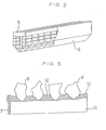
- band saw blades were manufactured through the process steps mentioned below, and with the electroplating tank in Figs. 1 and 2.
- the cathode electrode chamber of the above-mentioned structure is specifically disposed in the electroplating bath and part of the anode liquid is recirculated and filled in the cathode chamber from the above such that the abrasive particles are held in the bottom section thereof and prevented from diffusion. Consequently, the plating conditions such as, for example pH, metal concentration, etc. in the cathode chamber can be stabilized and controlled, so that the deposition of the abrasive particles can be controlled at a constant amount while the abrasive particles can be bonded onto the base metal uniformly and evenly.
- the abrasive particles are automatically held as a layer having a constant height in the bottom part of the cathode chamber by simply charging the abrasive particles into the cathode chamber, and the same effect as that obtained by agitation can be achieved by circulating the liquid through the layer so that not only the plating conditions in the cathode chamber can be stabilized, but also the abrasive particles to be used need be prepared by a necessary but minimum amount, thereby permitting on economical production. Furthermore, since the operating conditions can be controlled and stabilized, the present invention provides an optimum method for manufacturing electroplated tools, in that the tools can be continuously manufactured, etc.
- the method of manufacturing electroplated tools is suitable for manufacturing various tools for grinding, polishing, cutting, etc., wherein abrasive particles made of diamond, cubic boron nitride, fine ceramics,etc. are codeposited and bonded together with a metal such as nickel or copper, onto the base metals of various tools by electroplating.
Landscapes
- Engineering & Computer Science (AREA)
- Chemical & Material Sciences (AREA)
- Manufacturing & Machinery (AREA)
- Mechanical Engineering (AREA)
- Chemical Kinetics & Catalysis (AREA)
- Electrochemistry (AREA)
- Materials Engineering (AREA)
- Metallurgy (AREA)
- Organic Chemistry (AREA)
- Polishing Bodies And Polishing Tools (AREA)
Abstract
Procédé par lequel un abrasif granulaire, en combinaison avec un métal déposé, est déposé sur un métal de base pour obtenir une électrodéposition sur un outil par dépôt électrolytique. Une chambre de cathode (4) est formée dans un réservoir électrolytique (1) de sorte qu'une partie de la chambre de cathode (4) fait saillie au delà de la surface de l'anolyte (Sa). Une couche d'abrasif granulaire (8) est formée sur le fond de la chambre de cathode (4). Une partie de l'anolyte dans une chambre d'anode (7) est versée dans la chambre de cathode (4) depuis son côté supérieur de sorte qu'une différence de tête (Sc-Sa) est formée entre la surface du catholyte (Sc) et la surface de l'anolyte (sa), créant des conditions de placage telles que le pH du catholyte et la concentration du métal sont régulés de sorte que l'abrasif granulaire (8) est déposé sur un métal de base (3) sans diffuser la couche abrasive granulaire (8). Ce procédé est utilisé avantageusement pour fabriquer un outil plaqué par électrodéposition, et permet de déposer un abrasif granulaire, tel qu'une poudre de diamants, du nitrure de bore cubique ou une fine céramique, sur une base métallique, avec un métal, tel que du nickel ou du cuivre, pour produire différents outils de meulage, polissage ou coupe.
Applications Claiming Priority (2)
| Application Number | Priority Date | Filing Date | Title |
|---|---|---|---|
| JP129349/84 | 1984-06-25 | ||
| JP12934984A JPS619600A (ja) | 1984-06-25 | 1984-06-25 | 電着工具の製造方法 |
Publications (2)
| Publication Number | Publication Date |
|---|---|
| EP0185091A1 true EP0185091A1 (fr) | 1986-06-25 |
| EP0185091A4 EP0185091A4 (en) | 1987-07-13 |
Family
ID=15007405
Family Applications (1)
| Application Number | Title | Priority Date | Filing Date |
|---|---|---|---|
| EP84903987A Pending EP0185091A4 (en) | 1984-06-25 | 1984-10-29 | Method for electrodeposition of metal and granular abrasive on a tool |
Country Status (3)
| Country | Link |
|---|---|
| EP (1) | EP0185091A4 (fr) |
| JP (1) | JPS619600A (fr) |
| WO (1) | WO1986000252A1 (fr) |
Cited By (4)
| Publication number | Priority date | Publication date | Assignee | Title |
|---|---|---|---|---|
| WO1998007902A1 (fr) * | 1996-08-21 | 1998-02-26 | Diamond Pauber S.R.L. | Procede pour produire un fil diamante prevu pour etre utilise dans du materiel de taille de pierres, et fil diamante produit selon ce procede |
| WO2013072687A3 (fr) * | 2011-11-16 | 2013-08-15 | Nanoridge Materials, Incorporated | Métal conducteur amélioré par un nanomatériau conducteur |
| CN105177678A (zh) * | 2015-10-09 | 2015-12-23 | 华晶精密制造股份有限公司 | 金刚石切割线上砂镀液装置 |
| AU2022462005B2 (en) * | 2022-06-21 | 2024-12-12 | Qingdao university of technology | Bionic desert beetle self-transporting bone microgrinding head and manufacturing process therefor |
Families Citing this family (3)
| Publication number | Priority date | Publication date | Assignee | Title |
|---|---|---|---|---|
| JPS63194786A (ja) * | 1987-02-04 | 1988-08-11 | 株式会社デンソー | 洗浄方法及び装置 |
| DE3706867A1 (de) * | 1987-03-04 | 1988-09-15 | Winter & Sohn Ernst | Schneidsegment fuer eine saege zur steinbearbeitung |
| US9174292B2 (en) * | 2008-04-16 | 2015-11-03 | United Technologies Corporation | Electro chemical grinding (ECG) quill and method to manufacture a rotor blade retention slot |
Family Cites Families (2)
| Publication number | Priority date | Publication date | Assignee | Title |
|---|---|---|---|---|
| JPS51754B1 (fr) * | 1970-04-28 | 1976-01-10 | ||
| US4079552A (en) * | 1974-11-06 | 1978-03-21 | Fletcher J Lawrence | Diamond bonding process |
-
1984
- 1984-06-25 JP JP12934984A patent/JPS619600A/ja active Pending
- 1984-10-29 EP EP84903987A patent/EP0185091A4/en active Pending
- 1984-10-29 WO PCT/JP1984/000517 patent/WO1986000252A1/fr not_active Ceased
Cited By (5)
| Publication number | Priority date | Publication date | Assignee | Title |
|---|---|---|---|---|
| WO1998007902A1 (fr) * | 1996-08-21 | 1998-02-26 | Diamond Pauber S.R.L. | Procede pour produire un fil diamante prevu pour etre utilise dans du materiel de taille de pierres, et fil diamante produit selon ce procede |
| WO2013072687A3 (fr) * | 2011-11-16 | 2013-08-15 | Nanoridge Materials, Incorporated | Métal conducteur amélioré par un nanomatériau conducteur |
| CN105177678A (zh) * | 2015-10-09 | 2015-12-23 | 华晶精密制造股份有限公司 | 金刚石切割线上砂镀液装置 |
| CN105177678B (zh) * | 2015-10-09 | 2017-08-29 | 华晶精密制造股份有限公司 | 金刚石切割线上砂镀液装置 |
| AU2022462005B2 (en) * | 2022-06-21 | 2024-12-12 | Qingdao university of technology | Bionic desert beetle self-transporting bone microgrinding head and manufacturing process therefor |
Also Published As
| Publication number | Publication date |
|---|---|
| WO1986000252A1 (fr) | 1986-01-16 |
| EP0185091A4 (en) | 1987-07-13 |
| JPS619600A (ja) | 1986-01-17 |
Similar Documents
| Publication | Publication Date | Title |
|---|---|---|
| US3957593A (en) | Method of forming an abrasive tool | |
| US4155721A (en) | Bonding process for grinding tools | |
| CN1263570A (zh) | 高质量型面很矮的铜箔制造工艺及由其制成的铜箔 | |
| US20060118427A1 (en) | Electrolyte bath for trivalent chromium plating | |
| CN1961099A (zh) | 用于电化学加工微特征工件的腔室、系统和方法 | |
| US5409593A (en) | Method and apparatus for selective electroplating using soluble anodes | |
| RU2281990C2 (ru) | Способ и установка для гальванического осаждения никеля, кобальта, сплавов никеля или сплавов кобальта с использованием периодических импульсов тока | |
| GB2364947A (en) | Production of gas separators for use in fuel cells and apparatus used therefore | |
| US3929592A (en) | Plating apparatus and method for rotary engine housings | |
| JP3411391B2 (ja) | 電解用電極および該電極の電解液槽への取付装置 | |
| WO1986000252A1 (fr) | Procede d'electrodeposition d'un metal et d'un abrasif granulaire sur un outil | |
| CA2504369C (fr) | Processus de revetement electrolytique d'un moule pour coulee en continu | |
| US4172771A (en) | Method and apparatus for electrolytically producing compound workpieces | |
| US7560015B2 (en) | Process for electrolytic coating of a strand casting mould | |
| EP0004449B1 (fr) | Procédé de fixation pour outils abrasifs | |
| EP0847455B1 (fr) | Fabrication de dresseurs au diamant | |
| JPH04318198A (ja) | 砥粒子の分散めっき方法 | |
| EP0033956B1 (fr) | Anode stable à base de bioxyde de plomb et procédé pour sa fabrication | |
| KR102164682B1 (ko) | 와이어 쏘우 코팅을 위한 거품 발생 장치 및 와이어 쏘우 제조 장치 | |
| JP2736690B2 (ja) | 電着砥石の製造方法 | |
| JPH091455A (ja) | 砥粒被覆ワイヤ工具、その製造方法及び装置 | |
| KR19990001959A (ko) | 전착(electrodeposition)을 이용한 연삭 및 연마공구의 제조방법 | |
| CN222540896U (zh) | 一种金刚石工具的电镀设备 | |
| JP4378260B2 (ja) | ワイヤソー作製方法およびワイヤソー作製装置 | |
| EP0100777A1 (fr) | Procédé pour électro-plaquer de pièces métalliques |
Legal Events
| Date | Code | Title | Description |
|---|---|---|---|
| PUAI | Public reference made under article 153(3) epc to a published international application that has entered the european phase |
Free format text: ORIGINAL CODE: 0009012 |
|
| 17P | Request for examination filed |
Effective date: 19860221 |
|
| AK | Designated contracting states |
Kind code of ref document: A1 Designated state(s): CH DE GB LI |
|
| A4 | Supplementary search report drawn up and despatched |
Effective date: 19870713 |
|
| STAA | Information on the status of an ep patent application or granted ep patent |
Free format text: STATUS: THE APPLICATION IS DEEMED TO BE WITHDRAWN |
|
| RIN1 | Information on inventor provided before grant (corrected) |
Inventor name: FUNAKUBO, MASATOSHI Inventor name: YOSHIHARA, NAOMI |