EP0185120A1 - Communication sous-marine - Google Patents
Communication sous-marine Download PDFInfo
- Publication number
- EP0185120A1 EP0185120A1 EP19840307855 EP84307855A EP0185120A1 EP 0185120 A1 EP0185120 A1 EP 0185120A1 EP 19840307855 EP19840307855 EP 19840307855 EP 84307855 A EP84307855 A EP 84307855A EP 0185120 A1 EP0185120 A1 EP 0185120A1
- Authority
- EP
- European Patent Office
- Prior art keywords
- digit
- channels
- fed
- channel
- digits
- Prior art date
- Legal status (The legal status is an assumption and is not a legal conclusion. Google has not performed a legal analysis and makes no representation as to the accuracy of the status listed.)
- Granted
Links
- XLYOFNOQVPJJNP-UHFFFAOYSA-N water Substances O XLYOFNOQVPJJNP-UHFFFAOYSA-N 0.000 claims abstract description 16
- 238000000034 method Methods 0.000 claims abstract description 14
- 238000001514 detection method Methods 0.000 claims description 5
- 230000000694 effects Effects 0.000 abstract description 5
- 230000005540 biological transmission Effects 0.000 description 16
- 239000003550 marker Substances 0.000 description 6
- 230000011664 signaling Effects 0.000 description 2
- 230000003111 delayed effect Effects 0.000 description 1
- 238000010586 diagram Methods 0.000 description 1
- 230000007257 malfunction Effects 0.000 description 1
- 230000002035 prolonged effect Effects 0.000 description 1
- 230000001360 synchronised effect Effects 0.000 description 1
Images
Classifications
-
- H—ELECTRICITY
- H04—ELECTRIC COMMUNICATION TECHNIQUE
- H04L—TRANSMISSION OF DIGITAL INFORMATION, e.g. TELEGRAPHIC COMMUNICATION
- H04L27/00—Modulated-carrier systems
- H04L27/10—Frequency-modulated carrier systems, i.e. using frequency-shift keying
-
- H—ELECTRICITY
- H04—ELECTRIC COMMUNICATION TECHNIQUE
- H04L—TRANSMISSION OF DIGITAL INFORMATION, e.g. TELEGRAPHIC COMMUNICATION
- H04L27/00—Modulated-carrier systems
- H04L27/26—Systems using multi-frequency codes
Definitions
- This invention relates to underwater communication system.
- Acoustic waves of sonic or ultrasonic frequency can be transmitted through water for long distances. Refraction effects occur due to changes in the properties of the water for example due to temperature variation and, as a result of this, it commonly occurs that transmission from one point to another may occur over two or more different paths. If these paths have different lengths, or different velocities of propagation, then there is a time delay between the arrival of the signals over the different paths.
- the present invention is concerned more particularly with a digital communication system.
- a simple train of digital signals where the presence and absence of a signal indicates 1 and 0 or vice versa, it is necessary at the receiving end to determine both the presence and the absence of a transmitted pulse. Errors can occur due to pulses being repeated by delayed transmission over a second path. Refraction effects may also cause failure to receive a digital pulse.
- successive digits of a message in serial form are sent using, for each digit, a selected sonic or ultrasonic frequency which differs from the frequency used for the preceding or succeeding digit.
- This method permits of the loss of a transmitted signal or duplication of reception of a signal to be detected at a distant receiver.
- a method of transmitting digital data through water as acoustic signals comprises the steps of separating and feeding successive digits of a serial input at the transmitter each into a selected one of either three or four channels such that each digit is fed into a different channel from its preceding digit and such that, after a digit has been fed into one channel, the next successive digit is fed into one or other of two further channels separate from the channel into which the preceding digit is fed, the further channel being selected in accordance with whether the digit is a 1 or 0 or whether the digit is the same or different from the preceding digit, and then transmitting the signals in the separate channels as acoustic pulses on different sonic or ultrasonic frequencies, and, at the receiving end, receiving the signals of the different sonic or ultrasonic frequency to obtain the digital pulses.
- the pulses received in succession from the various different channels would usually be recombined into serial form.
- the successive digits should appear on different channel outputs when the signals are received and a logic system may be provided to check this so enabling the loss of an input signal or the duplication of reception of a single signal to be detected.
- the successive digits of information are separated and fed into three channels such that successive digits are fed into different channels and such that, where two successive digits are the same, the last digit of said two equal digits is fed into a channel different from those for the previous two digits.
- This arrangement requires only three sonic or ultrasonic transmission frequencies through the water.
- a four-channel system is employed with the 1's and 0's of odd digits fed into one or other of a first pair of channels according to whether the digit to be recorded is a 1 or a 0, and with the 1's or 0's of even digits fed into one or other of a second pair of channels according to whether the digit to be recorded is a 1 or 0.
- Such an arrangement requires the use of four sonic or ultrasonic transmission frequencies.
- the data-rate can be slowed down to accommodate the echo component. Should the echo component be so severe that any one signal completely merges with the signal following, causing a completely confused signalling situation, the signalling can be made to be discontinuous so that reverberating signals can die before the reception of the next transmitted bit.
- the reception device must be free of any time constraint; a very high integrity of error-detection becomes significant and the use of "ARQ" is important.
- the invention furthermore includes within its scope apparatus for transmitting digital data through water from a transmitting station to a receiving station wherein the transmitter includes means for separating and feeding digits of input serial form each into a selected one of three or four channels, such that each digit is fed into a different channel from its preceding digit and such that, after a digit has been fed into one channel, the next successive digit is fed into one or other of two further channels separate from the channel into which the preceding digit is fed, the further channel being selected in accordance with whether the digit is a 1 or C or whether the digit is the same or different from the preceding digit, means for radiating the digits from th E : various channels as pulses of different sonic or ultrasonic frequencies for the various channels and, at a receiving station means for receiving the sonic or ultrasonic frequencies on the various channels and demodulating the received signals to obtain digital pulses.
- error detection means may be provided for checking that digits are received from the appropriate channels. For example in a four-channel system one digit would be received from either the first or second channel and the next digit from either the third or fourth channel. It is readily possible to provide simple logical checks on the accuracy of the information in this way. Such checking system may be arranged, after receiving a pulse on one channel, to disregard any further pulses on that channel until the appropriate reception has occurred on other channels. It is thus readily possible to correct for the effects of transmission over multiple paths for a one-way or a two-way communication link between moving and/or fixed locations under water.
- a transducer device carried on a buoy or other floating or fixed object or on a dunking buoy, may be provided to receive radio signals and to convert them into appropriate acoustic signals or vice versa.
- the encoding of digital data into three or four channels for transmission using acoustic waves or the combination of signals received on three or four different frequency acoustic waves into serial form might be effected at the location of the transducer or may in some cases more conveniently be effected elsewhere such as for example at the remote end of the radio portion of the link.
- the radio-to-sonar or sonar-to-radio link may comprise a simple modulation translator e.g. radio-to-sonar or sonar-to-radio translator. Because of the differing data rates possible for the sonar and radio links, it may be preferred however to employ a data store and interface for forwarding the data.
- the use of the three or four channels as described above for acoustic transmission through water enables a very great improvement to be obtained in the underwater communication despite instabilities in the transmission path, the occurrence of multiple transmission paths and interference due to transients.
- the data is preferably transmitted in blocks of predetermined length, i.e. having a predetermined number of possible digits.
- Block or inter-block markers may be employed to bracket the data stream or streams. This enables a receiver, by checking these markers, to recognise message blocks and to ignore noise when no data is being transmitted.
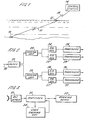
- FIG. 1 there is shown diagrammatically an underwater weapon 10 which might typically be located on or buried within the sea bed and which is controlled via a communication link including an underwater path 11 between the weapon and a transducer station 12 typically located on a buoy. From the transducer station 12 communication is effected over a radio link between that station and a control station 14 which may be a fixed land based station or may be a mobile station for example a ship or aircraft.
- the communication link may be a two-way link or a one-way link depending on the requirements of the weapon system.
- the present invention is concerned more particularly with the underwater link 11 but it will be appreciated that certain of the coding or decoding operations might be effected at the control station 14 rather than at the transducer station 12 and, in this case, the appropriate signals would have to be transmitted over the radio link as well as over the acoustic link through the sea.
- the input data on a line 20 is fed to a first switching device 21 which operates to feed alternate units of the digital information, as short duration pulses, to two sensing units 22, 23 so that odd digits (i.e. the first, third, fifth etc.) in the serial input are fed to the sensing unit 22 whilst even digits (i.e. the second, fourth etc.) are fed to the sensing unit 23.
- the sensing units 22, 23 are responsive to the digital values of the input digit and the sensing unit 22 feeds 0's as pulses to modulate a first acoustic signal generator 24 generating signals of sonic or ultrasonic frequency suitable for transmission along the underwater path 11.
- the sensing unit 22 feeds 1's as pulses to modulate a second acoustic signal generator 25 operating under different frequency.
- the sensing unit 23 feeds 0's as pulses to modulate a third acoustic signal generator 26 and 1's as pulses to modulate a fourth acoustic signal generator 27.
- the four signal generators 24 to 27 thus provide respectively signals of four different frequencies which are fed to transducers 28 to 31 respectively to radiate the pulse modulated acoustic waves through the water.
- the transmitter has four separate channels and these can be tuned as appropriate to the various different frequencies. It will be appreciated that, by using switchably tuned devices, it would become possible to use common components for the four channels.
- a receiver and demodulating unit 50 which provides output pulses in sequence which are fed to a staticiser 51.
- a staticiser 51 This may conveniently be a register of the kind described in U .K.Patent Specification No.852873.
- the output from this staticiser is.fed to an operating device or data responsive means 52 making use of the received digital data.
- the output from the staticiser 51 is fed also to a checking unit 54.
- the output pulses corresponding to the first and second channels, i.e. the odd digits are fed together to a counter which counter has, after each digit, to be reset before it can count the next digit.
- the resetting signal is obtained from the digits on the third and fourth channels. It will thus be seen that for example if data is transmitted in groups of a predetermined number of digits, the counter will only count the required number of digits if every odd digit is received and if an even digit is received after each odd digit. This checking thus gives a very high degree of protection against spurious pulses which might arise in the acoustic transmission path and against any momentary or prolonged failure to receive signals, e.g. due to instability of the transmission path. It also provides protection against errors due to a single pulse being received two or more times due to multiple path transmission. In an acoustic transmission system, this possibility of multiple path transmission is of particular significance.
- the output of the logic unit 54 may be fed back to the staticiser 51.
- the output from the logic unit 54 may be fed to the record or display unit 53, as shown at 56, to inhibit the display or recording of incorrect information or to identify failure to receive correct information.
- the digital data has been transmitted using a four channel system. It is alternatively possible to encode the information for use on a three-channel system.
- One convenient way of so encoding the information operates according to the following rule. If two successive data bits are the same, then the last bit of said two bits is fed into a different channel from the previous two bits and successive bits are fed into different channels. Thus, if the channels are A, B and C, if the first bit is a 1 it is fed for example into channel A. If the second bit is a 0 it is fed to channel B. Hence alternating 1's and 0's are encoded ABABAB till
- the C channel has now become the '0' channel so 10100101 becomes ABABCACA.
- the output of the three-channel encoder will be ABABCACAB, the B channel now becoming the 1 channel because of the successive 1's.
- the output of the encoder is ABABCACABC rather than ABABCACABA as might have been expected because when two successive equal value bits occur the last of said bits must be fed into a different channel to the channels into which the two preceding bits were fed.
- block or inter-block markers it is convenient to employ block or inter-block markers to enable the receiving apparatus to bracket a message block in a data stream or data streams. This enables the receiving apparatus to ignore noise when no data is being transmitted.
- an encoding method which is independent of time, one can wait forever if there is a break in transmission.
- the receiving technique is enhanced if the period of the message is known without taking account of time. This can be readily achieved by a unique signal defining the start of the message and a unique signal definition of the end of message. By cascading different messages with this unique signal between each, an independent integrity check can be made on each message separately.
- This unique signal can be made, for example, from the components of the four frequency used to encode the message as described above by using a combination such that it cannot be mistaken as part of the message itself, and the message component cannot in turn be mistaken for the beginning or end of block marker. This is achieved as follows:-
- the beginning of the message can be defined as even zero followed by an even one.
- the message then follows starting with its odd component for example an odd zero and ending with an even component for example an even one.
- the end of message can be defined as an odd zero followed by an odd one. If part of the message start marker is missing then no part of the message can reproduce or be mistaken for the start sequence and even if it did the integrity check placed on the number of characters known to be in the message would sh ow the message to be in error. Likewise if part of the message due to noise were to reproduce the end of message marker or if part of the message is missing before the end of block marker is detected then there will be an error.
Landscapes
- Engineering & Computer Science (AREA)
- Computer Networks & Wireless Communication (AREA)
- Signal Processing (AREA)
- Measurement Of Velocity Or Position Using Acoustic Or Ultrasonic Waves (AREA)
- Addition Polymer Or Copolymer, Post-Treatments, Or Chemical Modifications (AREA)
- Arrangements For Transmission Of Measured Signals (AREA)
Priority Applications (3)
| Application Number | Priority Date | Filing Date | Title |
|---|---|---|---|
| EP84307855A EP0185120B1 (fr) | 1984-11-13 | 1984-11-13 | Communication sous-marine |
| AT84307855T ATE48927T1 (de) | 1984-11-13 | 1984-11-13 | Unterwasseruebertragung. |
| DE8484307855T DE3480819D1 (de) | 1984-11-13 | 1984-11-13 | Unterwasseruebertragung. |
Applications Claiming Priority (1)
| Application Number | Priority Date | Filing Date | Title |
|---|---|---|---|
| EP84307855A EP0185120B1 (fr) | 1984-11-13 | 1984-11-13 | Communication sous-marine |
Publications (2)
| Publication Number | Publication Date |
|---|---|
| EP0185120A1 true EP0185120A1 (fr) | 1986-06-25 |
| EP0185120B1 EP0185120B1 (fr) | 1989-12-20 |
Family
ID=8192808
Family Applications (1)
| Application Number | Title | Priority Date | Filing Date |
|---|---|---|---|
| EP84307855A Expired EP0185120B1 (fr) | 1984-11-13 | 1984-11-13 | Communication sous-marine |
Country Status (3)
| Country | Link |
|---|---|
| EP (1) | EP0185120B1 (fr) |
| AT (1) | ATE48927T1 (fr) |
| DE (1) | DE3480819D1 (fr) |
Cited By (1)
| Publication number | Priority date | Publication date | Assignee | Title |
|---|---|---|---|---|
| WO2005122446A1 (fr) * | 2004-06-12 | 2005-12-22 | Sonardyne International Ltd. | Systeme sous-marin de communications robustes |
Citations (4)
| Publication number | Priority date | Publication date | Assignee | Title |
|---|---|---|---|---|
| US3990071A (en) * | 1973-08-31 | 1976-11-02 | Hitachi, Ltd. | Data transmission system using frequency permutation codes |
| US4011511A (en) * | 1974-07-24 | 1977-03-08 | The Singer Company | Frequency-shift digital data link and digital frequency detection system |
| US4425666A (en) * | 1982-01-29 | 1984-01-10 | Motorola Inc. | Data encoding and decoding communication system for three frequency FSK modulation and method therefor |
| US4463452A (en) * | 1982-09-13 | 1984-07-31 | The United States Of America As Represented By The Secretary Of The Navy | Tracking and telemetry system for severe multipath acoustic channels |
-
1984
- 1984-11-13 DE DE8484307855T patent/DE3480819D1/de not_active Expired - Fee Related
- 1984-11-13 EP EP84307855A patent/EP0185120B1/fr not_active Expired
- 1984-11-13 AT AT84307855T patent/ATE48927T1/de not_active IP Right Cessation
Patent Citations (4)
| Publication number | Priority date | Publication date | Assignee | Title |
|---|---|---|---|---|
| US3990071A (en) * | 1973-08-31 | 1976-11-02 | Hitachi, Ltd. | Data transmission system using frequency permutation codes |
| US4011511A (en) * | 1974-07-24 | 1977-03-08 | The Singer Company | Frequency-shift digital data link and digital frequency detection system |
| US4425666A (en) * | 1982-01-29 | 1984-01-10 | Motorola Inc. | Data encoding and decoding communication system for three frequency FSK modulation and method therefor |
| US4463452A (en) * | 1982-09-13 | 1984-07-31 | The United States Of America As Represented By The Secretary Of The Navy | Tracking and telemetry system for severe multipath acoustic channels |
Cited By (3)
| Publication number | Priority date | Publication date | Assignee | Title |
|---|---|---|---|---|
| WO2005122446A1 (fr) * | 2004-06-12 | 2005-12-22 | Sonardyne International Ltd. | Systeme sous-marin de communications robustes |
| US20110096632A1 (en) * | 2004-06-12 | 2011-04-28 | Pearce Christopher D | Robust underwater communication system |
| US8139442B2 (en) * | 2004-06-12 | 2012-03-20 | Sonardyne International Ltd. | Robust underwater communication system |
Also Published As
| Publication number | Publication date |
|---|---|
| ATE48927T1 (de) | 1990-01-15 |
| DE3480819D1 (de) | 1990-01-25 |
| EP0185120B1 (fr) | 1989-12-20 |
Similar Documents
| Publication | Publication Date | Title |
|---|---|---|
| CA2004109C (fr) | Systeme de telemetrie sismique a trajets de transmission multiples | |
| US3310631A (en) | Communication system for the selective transmission of speech and data | |
| US5121366A (en) | Underwater communication system | |
| GB936419A (en) | Method and apparatus for data transmission | |
| US5224105A (en) | Transfer of data without loss over a noisy channel | |
| US3611298A (en) | Data transmission system | |
| US3939465A (en) | Remote underwater device activating system | |
| GB2139788A (en) | Underwater communication | |
| Baggeroer et al. | DATS-a digital acoustic telemetry system for underwater communications | |
| EP0185120B1 (fr) | Communication sous-marine | |
| RU192243U1 (ru) | Двухканальное гидроакустическое устройство управления объектами с повышенной помехоустойчивостью | |
| Eck et al. | High speed digital acoustic telemetry system | |
| JP2555582B2 (ja) | Cmi符号誤り検出回路 | |
| SU1403379A1 (ru) | Устройство дл передачи и приема самосинхронизирующихс кодограмм | |
| JPS57136845A (en) | Coding and transfer system of information data | |
| SU1061277A1 (ru) | Система передачи дискретной информации | |
| JPH0142534B2 (fr) | ||
| Chase | A Tracking and Telemetry System for Severe Multipath Acoustic Channels | |
| JPS5814104B2 (ja) | 情報伝送方式 | |
| JPS6010838A (ja) | 送受信ネツトワ−クシステム | |
| Falahati et al. | Long and Short Range Multipath Propagation Models for Use in the Transmission of High-Speed Data through Underwater Channels | |
| JPS5797249A (en) | Data transmission system | |
| JPS5797250A (en) | Data transmission system for automatic retransmission request system | |
| Comerford | Highly reliable transmission-checking scheme for digital data links | |
| JPS6041900B2 (ja) | 送信多重化方式 |
Legal Events
| Date | Code | Title | Description |
|---|---|---|---|
| PUAI | Public reference made under article 153(3) epc to a published international application that has entered the european phase |
Free format text: ORIGINAL CODE: 0009012 |
|
| AK | Designated contracting states |
Kind code of ref document: A1 Designated state(s): AT BE CH DE FR IT LI LU NL SE |
|
| RAP1 | Party data changed (applicant data changed or rights of an application transferred) |
Owner name: UNDERWATER STORAGE LIMITED |
|
| RAP1 | Party data changed (applicant data changed or rights of an application transferred) |
Owner name: UNDERWATER STORAGE LIMITED |
|
| 17P | Request for examination filed |
Effective date: 19861228 |
|
| 17Q | First examination report despatched |
Effective date: 19880808 |
|
| GRAA | (expected) grant |
Free format text: ORIGINAL CODE: 0009210 |
|
| AK | Designated contracting states |
Kind code of ref document: B1 Designated state(s): AT BE CH DE FR IT LI LU NL SE |
|
| PG25 | Lapsed in a contracting state [announced via postgrant information from national office to epo] |
Ref country code: NL Effective date: 19891220 Ref country code: LI Effective date: 19891220 Ref country code: IT Free format text: LAPSE BECAUSE OF FAILURE TO SUBMIT A TRANSLATION OF THE DESCRIPTION OR TO PAY THE FEE WITHIN THE PRESCRIBED TIME-LIMIT;WARNING: LAPSES OF ITALIAN PATENTS WITH EFFECTIVE DATE BEFORE 2007 MAY HAVE OCCURRED AT ANY TIME BEFORE 2007. THE CORRECT EFFECTIVE DATE MAY BE DIFFERENT FROM THE ONE RECORDED. Effective date: 19891220 Ref country code: CH Effective date: 19891220 Ref country code: BE Effective date: 19891220 Ref country code: AT Effective date: 19891220 |
|
| REF | Corresponds to: |
Ref document number: 48927 Country of ref document: AT Date of ref document: 19900115 Kind code of ref document: T |
|
| REF | Corresponds to: |
Ref document number: 3480819 Country of ref document: DE Date of ref document: 19900125 |
|
| ET | Fr: translation filed | ||
| REG | Reference to a national code |
Ref country code: CH Ref legal event code: PL |
|
| NLV1 | Nl: lapsed or annulled due to failure to fulfill the requirements of art. 29p and 29m of the patents act | ||
| PLBE | No opposition filed within time limit |
Free format text: ORIGINAL CODE: 0009261 |
|
| STAA | Information on the status of an ep patent application or granted ep patent |
Free format text: STATUS: NO OPPOSITION FILED WITHIN TIME LIMIT |
|
| PG25 | Lapsed in a contracting state [announced via postgrant information from national office to epo] |
Ref country code: LU Free format text: LAPSE BECAUSE OF NON-PAYMENT OF DUE FEES Effective date: 19901130 |
|
| 26N | No opposition filed | ||
| EAL | Se: european patent in force in sweden |
Ref document number: 84307855.1 |
|
| PGFP | Annual fee paid to national office [announced via postgrant information from national office to epo] |
Ref country code: FR Payment date: 19951229 Year of fee payment: 12 Ref country code: DE Payment date: 19951229 Year of fee payment: 12 |
|
| PGFP | Annual fee paid to national office [announced via postgrant information from national office to epo] |
Ref country code: SE Payment date: 19961129 Year of fee payment: 13 |
|
| PG25 | Lapsed in a contracting state [announced via postgrant information from national office to epo] |
Ref country code: FR Effective date: 19970731 |
|
| PG25 | Lapsed in a contracting state [announced via postgrant information from national office to epo] |
Ref country code: DE Effective date: 19970801 |
|
| REG | Reference to a national code |
Ref country code: FR Ref legal event code: ST |
|
| PG25 | Lapsed in a contracting state [announced via postgrant information from national office to epo] |
Ref country code: SE Free format text: LAPSE BECAUSE OF NON-PAYMENT OF DUE FEES Effective date: 19971114 |
|
| EUG | Se: european patent has lapsed |
Ref document number: 84307855.1 |